In the mining operations of metal mines, haul roads serve as critical infrastructure for ore transport, equipment movement, and personnel access. However, these roads are highly susceptible to damage from subsidence over goaf areas, slope deformation, and blast-induced vibrations, leading to pavement沉降, cracking, and slope collapses. Consequently, frequent and accurate monitoring is essential for safety and operational continuity. Traditional surveying methods, such as total station measurements or static GNSS surveys, suffer from limitations like small coverage area, low efficiency, and high operational costs, making them ill-suited for the large-scale, high-frequency monitoring demands of expansive mining areas. In contrast, China UAV drone technology, with its superior mobility, extensive coverage, high data acquisition efficiency, and cost-effectiveness, has seen widespread adoption in mine surveying. This article systematically details the technical procedures for employing China UAV drone photogrammetry for road update monitoring in metal mines, specifying key parameters and operational essentials for each stage to provide a directly implementable technical framework.
Technical Principles of UAV Photogrammetry for Mine Road Monitoring
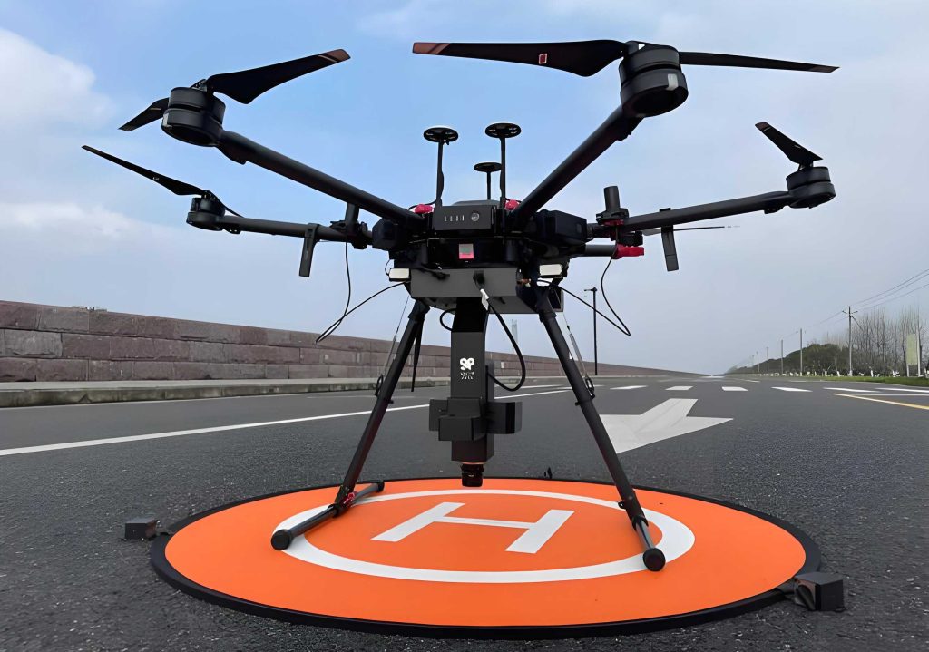
The effectiveness of UAV-based monitoring hinges on integrated hardware and sophisticated data processing. The platform, a China UAV drone, is typically equipped with a high-precision GNSS module, an Inertial Measurement Unit (IMU), and a high-resolution aerial camera. Flying along pre-programmed routes, the system captures systematic imagery of the target road corridors.
| System Component | Primary Function | Key Performance Metrics |
|---|---|---|
| GNSS Module | Provides centimeter-level geotagging for each image. | Real-Time Kinematic (RTK) or Post-Processed Kinematic (PPK) positioning. |
| Inertial Measurement Unit (IMU) | Records and compensates for aircraft attitude (pitch, roll, yaw). | Ensures geometric accuracy independent of flight dynamics. |
| Aerial Camera | Captures high-resolution overlapping imagery. | Resolution ≥20 MP, mechanical shutter, interval 15-20s, Ground Sampling Distance (GSD) of 0.05m-0.1m. |
The positioning accuracy is further refined using Ground Control Points (GCPs) surveyed with traditional instruments (e.g., total stations) to an error tolerance within ±3cm. The core data processing workflow involves several stages executed in software like Pix4D or ContextCapture:
- Aerial Triangulation (AT) & Dense Point Cloud Generation: This process matches features across overlapping images, solving for precise camera positions and generating a dense 3D point cloud. The reprojection error, a critical quality metric, should be minimized, ideally less than 1 pixel.
- Digital Elevation Model (DEM) Generation: The point cloud is filtered to classify ground points, from which a raster model representing the terrain surface is created.
- Digital Orthophoto Map (DOM) Generation: The original images are orthorectified using the DEM, correcting for relief displacement and camera tilt, to produce a planimetrically accurate image map.
The final products—DOM, DEM, and the 3D point cloud/model—serve complementary purposes for analysis. For dynamic monitoring, multi-temporal data sets are co-registered and analyzed. Horizontal displacement is analyzed via GIS overlay of DOMs. Vertical change, such as settlement, is calculated through DEM of Difference (DoD) analysis:
$$ \Delta H_{cell} = DEM_{t2}(x,y) – DEM_{t1}(x,y) $$
Where \( \Delta H_{cell} \) represents the elevation change at a given grid cell location \( (x, y) \) between time \( t1 \) and \( t2 \). Furthermore, deep learning algorithms can be applied to the DOM to automatically detect and classify road distresses like cracks and potholes. This multi-faceted approach enables comprehensive, high-precision, and dynamic monitoring of mine haul roads.
Technical Steps for UAV-Based Road Update Monitoring
Phase 1: Preliminary Preparation
Thorough preparation is paramount for ensuring monitoring accuracy and efficiency. This phase encompasses three main activities.
1.1 Site Investigation and Planning: A field reconnaissance is conducted to map the road network, identify start/end points, intersections, critical slopes, and existing distress areas. Mining operation schedules are obtained to plan flights during non-blasting periods and low traffic to minimize interference and safety risks. The coordinate system (e.g., China Geodetic Coordinate System 2000) and vertical datum are confirmed for consistency with existing mine survey data.
1.2 Equipment Selection: Selection is based on road characteristics and accuracy requirements (e.g., planimetric ≤5cm, vertical ≤3cm). A multi-rotor China UAV drone like the DJI Matrice 300 RTK is recommended for its stability, payload capacity, and RTK integration. Key specifications include:
- Flight Endurance: ≥40 minutes.
- Camera: Full-frame sensor with ≥20MP resolution, focal length 8-24mm, mechanical global shutter.
- Positioning: Integrated RTK/PPK module.
Auxiliary equipment includes a high-precision GNSS receiver for GCP surveying, and markers for GCPs.
1.3 Flight Mission Planning: Using flight planning software (e.g., DJI Terra, UgCS), a “parallel + crosshatch” flight pattern is typically designed. The flight height \( H \) is calculated based on the desired GSD, sensor width \( W_s \), focal length \( f \), and road width \( W_r \):
$$ H_{parallel} = \frac{W_r \times 0.8}{\tan(FOV_{horizontal}/2)} \quad \text{or} \quad H_{GSD} = \frac{GSD \times W_s}{f} $$
A height of 50-80m is common. Overlap rates are critical: 70%-80% frontal overlap and 80% side overlap ensure complete coverage and robust 3D modeling. Crosshatch lines are added over complex areas like intersections. Safe take-off and landing zones are designated away from obstacles and operational areas.
Phase 2: Data Acquisition
This phase involves the execution of the field survey, demanding strict adherence to protocols for both aerial and ground measurements.
2.1 Ground Control Point (GCP) Surveying: GCPs are the foundation for georeferencing accuracy. They are evenly distributed along the road corridor (e.g., 3-5 GCPs per km), placed on stable, visible features. Each GCP is clearly marked. High-precision GNSS receivers are used in static or fast-static mode, connecting to the mine’s base station or CORS network. Each point is observed for a sufficient period (e.g., ≥30 minutes) to obtain reliable centimeter-level coordinates.
| Parameter | Specification / Requirement |
|---|---|
| GCP Distribution | 3-5 points per km, covering road and slopes. |
| GCP Marking | Durable, high-contrast targets (painted cross, checkerboard). |
| GNSS Observation | Static/Fast-static mode, ≥30 min observation per point. |
| Coordinate Accuracy | Planimetric and vertical error ≤ 2cm. |
2.2 UAV Flight Operation: Pre-flight checks include battery levels, RTK signal lock (≥4 satellites), and camera settings (ISO, shutter speed). The China UAV drone then executes the autonomous mission. The operator monitors live telemetry and image feed. Flight speed is typically maintained between 5 m/s and 8 m/s to ensure image sharpness. For areas of specific interest (e.g., major cracks), manual flight mode at a lower altitude (30-50m) can be used to capture higher-resolution detail.
2.3 Data Transfer and Initial Quality Check: Post-flight, all raw images (JPG/RAW) and associated POS data (containing GNSS/IMU information) are downloaded and backed up. An initial quality check is performed:
- Image Quality: Reject blurred, over/under-exposed, or obstructed images. Valid image ratio should exceed 95%.
- GCP Data Check: Review processed GCP coordinates for outliers. Re-measure any point with suspected large errors.
Phase 3: Data Processing
Processing transforms raw imagery into actionable geospatial products through a structured pipeline.
| Processing Step | Actions & Key Parameters |
|---|---|
| 1. Initialization & Georeferencing | Import images and POS data. Input GCP coordinates and manually mark (pinpoint) them on 3+ images each. Perform lens distortion correction. |
| 2. Aerial Triangulation & Dense Reconstruction | Run feature matching and bundle adjustment. Generate dense point cloud with high density (point spacing ~5cm). Validate using reprojection error (target < 1 pixel). |
| 3. DEM Generation | Filter point cloud to ground class. Rasterize to generate DEM with grid size (e.g., 0.1m). Apply smoothing/filters. |
| 4. DOM Generation | Orthorectify images using the DEM. Mosaic images, set output resolution (e.g., 0.05m). Apply color balancing. |
| 5. Change Detection & Analysis | Co-register multi-temporal DOMs and DEMs. Perform visual and algorithmic comparison (e.g., DoD, CCDC). Quantify changes in area, volume, length, width. |
The precision of the final models is quantified using Check Points (CPs), independent points not used in the processing. The Root Mean Square Error (RMSE) is calculated:
$$ RMSE_{planimetric} = \sqrt{\frac{\sum_{i=1}^{n}(\Delta X_i^2 + \Delta Y_i^2)}{n}} $$
$$ RMSE_{vertical} = \sqrt{\frac{\sum_{i=1}^{n}(\Delta Z_i^2)}{n}} $$
Where \( \Delta X_i, \Delta Y_i, \Delta Z_i \) are the coordinate differences between the UAV-derived value and the surveyed true value for the \( i \)-th check point, and \( n \) is the number of check points. For mine road monitoring, target accuracies are typically \( RMSE_{planimetric} \leq 5 \)cm and \( RMSE_{vertical} \leq 3 \)cm.
Phase 4: Application of Results
The value of monitoring is realized by translating data into management actions.
4.1 Road Safety Assessment and Maintenance: The change detection report is used for risk stratification. Quantitative thresholds trigger specific responses.
| Identified Hazard | Threshold for Action | Potential Mitigation Measure |
|---|---|---|
| Crack | Length > 5m, Width > 5mm | Pressure injection of epoxy resin or asphalt sealant. |
| Settlement/Subsidence | Depth > 10cm | Layered filling and compaction (95% compaction degree). |
| Slope Deformation Rate | > 2 cm/month | Install warning signs, restrict heavy vehicle access, implement slope reinforcement. |
4.2 Road Network Planning and Optimization: High-precision DOM and DEM data inform planning. Bottlenecks and congested intersections are identified. Proposed new road alignments or widening projects can be designed and visualized using the 3D model. Earthwork volume \( V \) for a planned cut/fill area can be estimated from the DEM:
$$ V = \sum_{i=1}^{n} A_{cell} \cdot \Delta H_{design,i} $$
Where \( A_{cell} \) is the area of a grid cell and \( \Delta H_{design,i} \) is the required cut/fill height at that cell.
4.3 Data Archiving and System Integration: All deliverables (DOM, DEM, reports, raw data) are archived according to mine documentation standards. The road layers in the mine’s Geographic Information System (GIS) or digital twin platform are updated. A temporal database is maintained, enabling long-term trend analysis of deformation, predictive maintenance scheduling, and optimization of life-cycle management strategies.
Case Study Validation
The proposed technical steps were applied at a large-scale iron ore mine in China. The site comprised 15 km of haul roads, with three sections traversing known goaf areas, necessitating monthly high-precision monitoring.
Preliminary Preparation: A three-day site survey integrated pre-scanning data and geological radar reports to define the monitoring corridor (15km road + 50m buffer). A network of 45 permanently installed GCPs with forced-centering mounts was established using a total station. The platform selected was a DJI Matrice 300 RTK China UAV drone, equipped with a Zenmuse P1 45MP full-frame photogrammetry camera with mechanical shutter and RTK module. Flight parameters were set at 60m altitude, 80% side overlap, and 70% front overlap.
Data Acquisition: Flights were scheduled during weekend shutdowns. The autonomous mission captured 1,200 valid images. GCPs were surveyed with an RTK receiver, achieving a measurement RMSE of 1.5cm. For the high-risk goaf sections, an additional manual, low-altitude (30m) spiral flight was conducted, capturing 200 ultra-high-resolution images (GSD=0.03m).
Data Processing: Processing in Pix4Dmapper yielded a DOM with 0.05m resolution and a DEM with 0.1m grid spacing. Accuracy validation using 5 independent check points showed: \( RMSE_X = 0.7 \) cm, \( RMSE_Y = 0.9 \) cm (combined \( RMSE_{planimetric} = 1.1 \) cm), and \( RMSE_Z = 1.2 \) cm. Change detection analysis between consecutive months identified two settlement zones in the goaf area with depths of 8cm and 12cm, and one crack (6m long, 8mm wide). Slope analysis from the point cloud detected a local slope change of 3°.
Application of Results: The mine engineering department immediately implemented layered compaction (30cm layers, ≥95% compaction) in the settlement zones and pressure-injected epoxy into the crack. Warning signs were posted. A follow-up survey two weeks later confirmed stabilization (settlement rate reduced to <0.5 mm/month). Furthermore, the high-resolution DOM was used to simulate and optimize a key intersection in 3D, leading to a redesign that increased the turning radius from 15m to 20m and added traffic guides, resulting in a measured 20% improvement in traffic flow efficiency. All data was integrated into the mine’s digital twin platform for real-time visualization.
Conclusion
The standardized technical steps for China UAV drone-based photogrammetric monitoring of metal mine haul roads, detailing the workflow from preparation through data acquisition, processing, and application, provide a robust and practical framework. The case study demonstrates that this approach can significantly shorten the monitoring cycle to 3-5 days while achieving millimeter-to-centimeter-level accuracy that meets stringent mine safety management requirements, often at a substantially lower cost compared to traditional methods. The integration of China UAV drone technology represents a significant advancement in mining geomatics. Future developments will focus on augmenting this framework with complementary technologies like UAV-borne LiDAR for enhanced performance under dense vegetation or complex topography, and on advancing automated AI-driven analysis software for intelligent change recognition and report generation, thereby offering even more powerful technical support for the safety and efficiency of mining transportation infrastructure.