
In this thesis, I focus on the secure communication energy efficiency (EE) optimization problem in intelligent reflecting surface (IRS)-assisted unmanned aerial vehicle (UAV) communication systems. The widespread adoption of the fifth-generation (5G) mobile communication system has witnessed unmanned aerial vehicles (UAVs) playing increasingly critical roles in various civilian and military applications. However, the broadcast nature of wireless channels renders UAV communications vulnerable to eavesdropping, while the limited onboard energy of UAVs imposes significant challenges on system performance. By leveraging the capabilities of IRS in reshaping the wireless propagation environment, I aim to jointly design the IRS passive beamforming, UAV trajectory and velocity to maximize the confidential information transmission efficiency per unit energy consumption.
My research is motivated by the fundamental trade-off between the secrecy throughput and the propulsion energy consumption of an unmanned aerial vehicle. To this end, I introduce the concept of secure communication energy efficiency, which is defined as the ratio of the achievable secrecy rate to the total UAV propulsion energy consumption. I first investigate the scenario with ideal transceiver hardware, where I propose a manifold optimization (MO)-based alternating optimization framework. Then, I extend the study to a more practical scenario with transceiver hardware impairments (HIs), where I derive the statistical characterization of the HIs-induced distortion noise and develop a robust optimization scheme based on semidefinite programming (SDP) and successive convex approximation (SCA). Simulation results validate the effectiveness of my proposed schemes.
1. Introduction
The evolution of wireless communication systems has undergone several transformative stages, from the analog frequency division multiple access (FDMA)-based first-generation (1G) networks to the current fifth-generation (5G) systems. The emergence of 5G has defined three major application scenarios: enhanced mobile broadband (eMBB), ultra-reliable low-latency communications (URLLC), and massive machine-type communications (mMTC). These scenarios are supported by a variety of key technologies, including software-defined networking, network function virtualization, and beamforming. As research progresses toward the sixth-generation (6G) networks, the integration of unmanned aerial vehicles and intelligent reflecting surfaces is expected to play a pivotal role in achieving even higher spectral efficiency, energy efficiency, and coverage.
Unmanned aerial vehicles offer significant advantages over traditional terrestrial communication infrastructure, including high-mobility deployment, line-of-sight (LoS) link provisioning, and cost-effective coverage extension. A UAV can serve as an aerial base station, a relay node, or a data collector in various scenarios such as emergency rescue, environmental monitoring, and urban planning. In the military domain, UAVs are widely used for reconnaissance, surveillance, and secure data transmission. However, the energy limitation of UAVs remains a critical bottleneck that constrains their flight endurance and communication capability. Moreover, the air-to-ground wireless channels between a UAV and ground nodes exhibit strong LoS components, which, while beneficial for signal quality, also facilitate eavesdropping attacks. Consequently, ensuring secure communications while managing the limited onboard energy of an unmanned aerial vehicle has become an urgent research problem.
Intelligent reflecting surfaces have emerged as a promising technology to address these challenges. An IRS consists of a large number of low-cost passive reflecting elements, each capable of independently adjusting the phase of the incident signal. By intelligently configuring the phase shifts, an IRS can constructively combine the reflected signal with the direct signal at the intended receiver, thereby enhancing the desired signal power. Simultaneously, the phase shifts can be optimized to destructively interfere at unauthorized eavesdroppers, improving physical layer security. The deployment of IRSs in UAV-assisted networks thus provides an additional degree of freedom (DoF) for enhancing energy efficiency and security.
Existing research on IRS-assisted UAV secure communications has primarily focused on maximizing the secrecy rate under ideal hardware assumptions. However, practical transceivers inevitably suffer from HIs such as phase noise, power amplifier nonlinearities, and in-phase/quadrature-phase (I/Q) imbalance. Ignoring these effects can lead to significant performance degradation in real systems. Furthermore, the propulsion energy consumption of a UAV has been largely overlooked in many existing studies, despite its dominant role in the total energy budget. To bridge this gap, I develop a comprehensive framework that jointly optimizes the active beamforming at the UAV base station, the passive beamforming at the IRS, and the flight trajectory and velocity of the unmanned aerial vehicle, with the objective of maximizing the secure communication energy efficiency under realistic hardware constraints.
2. System Model and Problem Formulation
2.1 System Architecture
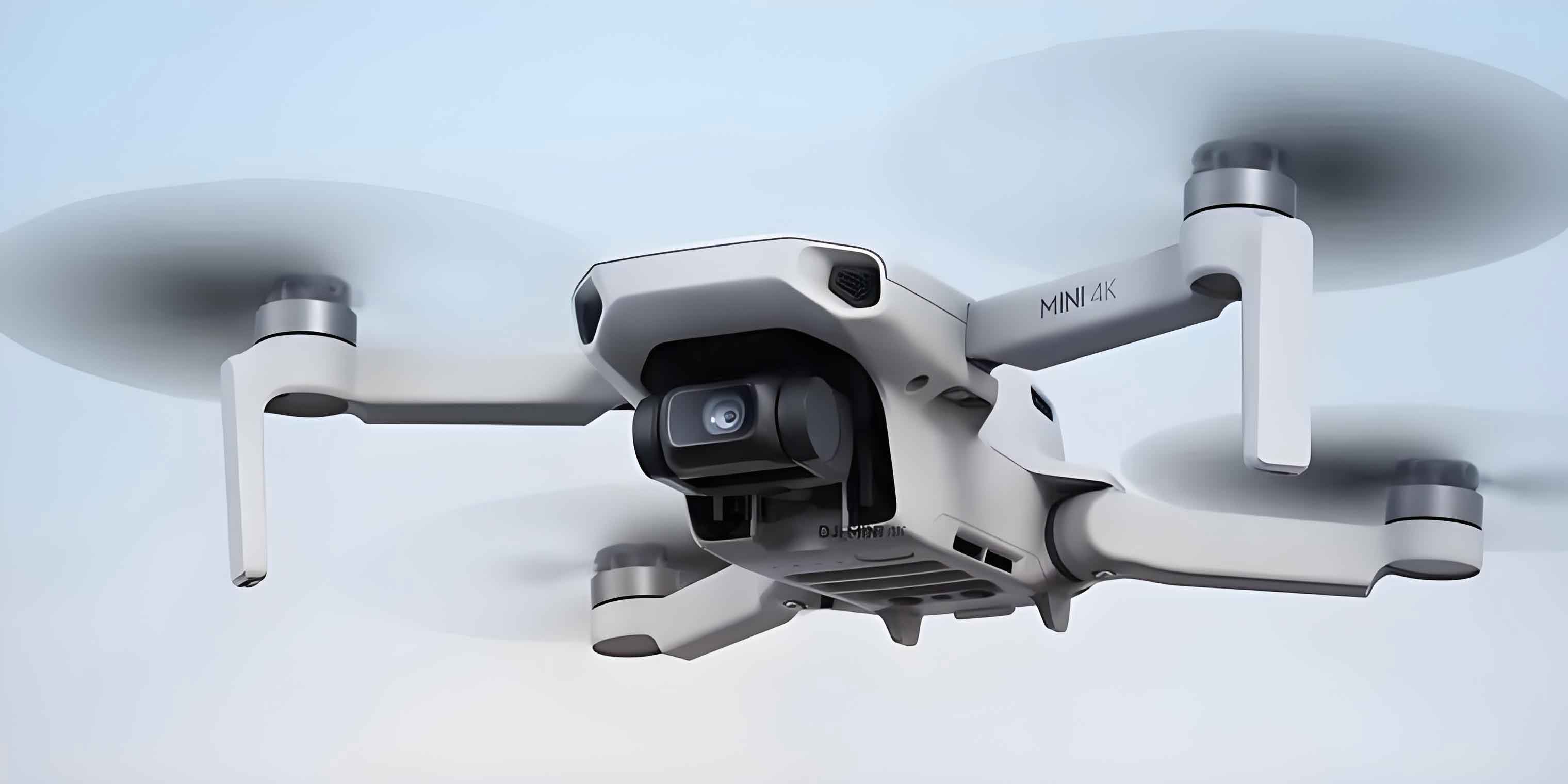
I consider an IRS-assisted secure UAV communication system, where a rotary-wing unmanned aerial vehicle serves as an aerial base station to transmit confidential information to a single-antenna legitimate user on the ground, while a single-antenna eavesdropper attempts to intercept the transmission. An IRS equipped with \(M\) passive reflecting elements is deployed on the surface of a building to assist the secure transmission. The horizontal positions of the legitimate user and the eavesdropper are denoted as \(\mathbf{w}_L = [x_L, y_L]^T\) and \(\mathbf{w}_E = [x_E, y_E]^T\), respectively. The IRS is located at horizontal coordinate \(\mathbf{w}_R = [x_R, y_R]^T\) with height \(z_R\). The UAV flies at a fixed altitude \(z_U\) during the total mission time \(T\), which is discretized into \(N\) time slots, each with duration \(\delta_t = T/N\). The horizontal position and velocity of the unmanned aerial vehicle in time slot \(n\) are denoted as \(\mathbf{q}[n] = [x[n], y[n]]^T\) and \(\mathbf{v}[n]\), respectively.
The flight trajectory constraints of the unmanned aerial vehicle are expressed as:
$$
\mathbf{q}[n] = \mathbf{q}[n-1] + \mathbf{v}[n]\delta_t \tag{1}
$$
$$
\mathbf{q}[1] = \mathbf{q}_I + \mathbf{v}[1]\delta_t \tag{2}
$$
$$
\mathbf{q}[N] = \mathbf{q}_F \tag{3}
$$
$$
\|\mathbf{v}[n]\| \leq V_{\max} \tag{4}
$$
where \(\mathbf{q}_I\) and \(\mathbf{q}_F\) denote the initial and final horizontal positions, respectively, and \(V_{\max}\) is the maximum allowable flight speed.
The IRS phase shift matrix in time slot \(n\) is given by \(\mathbf{\Theta}[n] = \mathrm{diag}(\theta_1[n], \theta_2[n], \ldots, \theta_M[n])\), where \(\theta_m[n] = e^{j\phi_m[n]}\) and \(\phi_m[n] \in [0, 2\pi)\) represents the phase shift of the \(m\)-th reflecting element.
2.2 Channel Models
I adopt realistic channel models that capture the key characteristics of air-to-ground and ground-to-ground links. The channel between the unmanned aerial vehicle and the IRS is dominated by the LoS component due to the absence of obstacles in the high-altitude environment. This channel is modeled as:
$$
\mathbf{H}_{UR}[n] = \rho d_{UR}^{-\alpha_{ur}}[n] \tilde{\mathbf{h}}_{UR}[n] \in \mathbb{C}^{M \times N_t} \tag{5}
$$
where \(\rho\) is the channel power gain at the reference distance of 1 meter, \(\alpha_{ur}\) is the path loss exponent, \(d_{UR}[n] = \|\mathbf{q}[n] – \mathbf{w}_R\|^2 + (z_U – z_R)^2\) is the distance between the UAV and the IRS, and \(\tilde{\mathbf{h}}_{UR}[n]\) is the array response matrix incorporating both the receive and transmit array responses.
The channels between the IRS and the ground users are modeled as Rician fading channels, reflecting the presence of both LoS and non-line-of-sight (NLoS) components:
$$
\mathbf{h}_{Ri} = \rho d_{Ri}^{-\alpha_{ri}} \left( \sqrt{\frac{\beta_i}{1+\beta_i}} \tilde{\mathbf{h}}_{Ri}^{\text{LoS}} + \sqrt{\frac{1}{1+\beta_i}} \tilde{\mathbf{h}}_{Ri}^{\text{NLoS}} \right) \tag{6}
$$
where \(i \in \{L, E\}\), \(\beta_i\) is the Rician factor, \(d_{Ri} = \|\mathbf{w}_R – \mathbf{w}_i\|\) is the distance between the IRS and the ground user, and \(\tilde{\mathbf{h}}_{Ri}^{\text{LoS}}\) and \(\tilde{\mathbf{h}}_{Ri}^{\text{NLoS}}\) denote the LoS and NLoS components, respectively.
Similarly, the channels between the unmanned aerial vehicle and the ground users follow Rician fading:
$$
\mathbf{h}_{Ui}[n] = \rho d_{Ui}^{-K}[n] \tilde{\mathbf{h}}_{Ui}[n] \tag{7}
$$
where \(K\) is the path loss exponent, \(d_{Ui}[n] = \sqrt{\|\mathbf{q}[n] – \mathbf{w}_i\|^2 + z_U^2}\) is the distance between the UAV and the ground user, and \(\tilde{\mathbf{h}}_{Ui}[n]\) is a complex Gaussian random vector with zero mean and unit variance.
2.3 Secrecy Rate and Energy Efficiency
With the channel models defined above, the received signals at the legitimate user and the eavesdropper in time slot \(n\) can be written as:
$$
y_L[n] = \left( h_{UL}[n] + \mathbf{h}_{RL}^H[n]\mathbf{\Theta}[n]\mathbf{h}_{UR}[n] \right) s[n] + g_L[n] \tag{8}
$$
$$
y_E[n] = \left( h_{UE}[n] + \mathbf{h}_{RE}^H[n]\mathbf{\Theta}[n]\mathbf{h}_{UR}[n] \right) s[n] + g_E[n] \tag{9}
$$
where \(s[n]\) is the transmitted signal satisfying \(\mathbb{E}\{|s[n]|^2\} = P\), and \(g_L[n] \sim \mathcal{CN}(0, \sigma_L^2)\) and \(g_E[n] \sim \mathcal{CN}(0, \sigma_E^2)\) are the additive white Gaussian noises (AWGN) at the legitimate user and the eavesdropper, respectively.
The achievable rates at the legitimate user and the eavesdropper are respectively:
$$
R_L[n] = B\log_2\left( 1 + \frac{P |h_{UL}[n] + \mathbf{h}_{RL}^H[n]\mathbf{\Theta}[n]\mathbf{h}_{UR}[n]|^2}{\sigma_L^2} \right) \tag{10}
$$
$$
R_E[n] = B\log_2\left( 1 + \frac{P |h_{UE}[n] + \mathbf{h}_{RE}^H[n]\mathbf{\Theta}[n]\mathbf{h}_{UR}[n]|^2}{\sigma_E^2} \right) \tag{11}
$$
where \(B\) is the channel bandwidth. The instantaneous secrecy rate is then given by:
$$
R_{\text{sec}}[n] = [R_L[n] – R_E[n]]^+ \tag{12}
$$
where \([x]^+ = \max(x, 0)\).
The total propulsion energy consumption of the rotary-wing unmanned aerial vehicle is modeled as:
$$
E_{\text{UAV}} = \sum_{n=1}^{N} \left( c_1 \|\mathbf{v}[n]\|^3 + \frac{c_2}{\|\mathbf{v}[n]\|} \right) \tag{13}
$$
where \(c_1\) and \(c_2\) are parameters related to the aircraft weight, wing area, and air density. I note that the communication-related energy consumption is typically negligible compared with the propulsion energy consumption. Therefore, I focus on the propulsion energy.
The secure communication energy efficiency is defined as:
$$
\zeta = \frac{\sum_{n=1}^{N} R_{\text{sec}}[n]}{E_{\text{UAV}}} \tag{14}
$$
2.4 Joint Optimization Problem
To maximize the secure communication energy efficiency of the IRS-assisted UAV system, I jointly optimize the IRS phase shift matrix \(\mathbf{\Theta}[n]\), the UAV flight trajectory \(\mathbf{Q} = \{\mathbf{q}[n]\}\), and the UAV flight velocity \(\mathbf{V} = \{\mathbf{v}[n]\}\). The optimization problem can be formulated as:
$$
\max_{\mathbf{\Theta}, \mathbf{Q}, \mathbf{V}} \zeta \tag{15}
$$
$$
\text{s.t.} \quad |\theta_m[n]| = 1, \quad \forall m, n \tag{15a}
$$
$$
\text{(1)} – \text{(4)} \tag{15b}
$$
The objective function is a non-convex fractional function with coupled variables, making the problem challenging to solve directly. I adopt an alternating optimization (AO) approach, where the original problem is decoupled into sub-problems solved iteratively.
3. Manifold Optimization-based Secure Energy Efficiency Scheme
3.1 UAV Trajectory and Velocity Optimization
With fixed IRS phase shifts, the sub-problem for optimizing the UAV trajectory and velocity is:
$$
\max_{\mathbf{Q}, \mathbf{V}} \zeta \tag{16}
$$
To handle the fractional objective, I introduce the Dinkelbach transformation with a positive auxiliary variable \(\lambda^{(r)}\) at iteration \(r\). The transformed problem becomes:
$$
\max_{\mathbf{Q}, \mathbf{V}} \sum_{n=1}^{N} \tilde{R}[n] – \lambda^{(r)} \hat{E}_{\text{UAV}} \tag{17}
$$
where \(\tilde{R}[n]\) is a concave lower bound of the secrecy rate obtained via the SCA technique, and \(\lambda^{(r)}\) is updated as:
$$
\lambda^{(r)} = \frac{\sum_{n=1}^{N} \tilde{R}^{(r)}[n]}{\hat{E}_{\text{UAV}}^{(r)}} \tag{18}
$$
To address the non-convexity in the rate expression, I introduce slack variables \(\mathbf{t}[n] = [t_1[n], t_2[n], t_3[n], t_4[n]]^T\). The UAV-ground distances and UAV-IRS distances are bounded by these slack variables through the following constraints:
$$
d_{UL}^{-\alpha}[n] \geq t_1[n], \quad d_{UR}^{-\alpha}[n] \geq t_2[n], \quad d_{UL}^{-\alpha}[n] \leq t_3[n], \quad d_{UR}^{-\alpha}[n] \leq t_4[n] \tag{19}
$$
Using the first-order Taylor expansions given in the following table, I construct global lower bounds for the non-convex terms.
| Function | Concave/Convex | Lower Bound at \(\mathbf{x}_0\) |
|---|---|---|
| \(\log_2(1+x)\) | Concave | \(\log_2(1+x_0) + \frac{(x-x_0)}{(1+x_0)\ln 2}\) |
| \(x^{-a}\) | Convex | \(x_0^{-a} – a x_0^{-a-1}(x – x_0)\) |
| \(\|\mathbf{q}[n] – \mathbf{w}\|^2\) | Convex | \(\|\mathbf{q}_0[n] – \mathbf{w}\|^2 + 2(\mathbf{q}_0[n]-\mathbf{w})^T(\mathbf{q}[n]-\mathbf{q}_0[n])\) |
| \(\|\mathbf{x}\|^2\) | Convex | \(\|\mathbf{x}_0\|^2 + 2\mathbf{x}_0^T(\mathbf{x} – \mathbf{x}_0)\) |
For the eavesdropper rate term, I introduce another slack variable \(\eta[n]\) such that:
$$
\frac{P}{\sigma_E^2} |h_{UE}[n] + \mathbf{h}_{RE}^H[n]\mathbf{\Theta}[n]\mathbf{h}_{UR}[n]|^2 \leq \eta[n] \tag{20}
$$
This constraint is then handled using SCA by constructing a global underestimator of the non-convex expression on the left-hand side. After applying the SCA transformations, the UAV trajectory and velocity sub-problem is converted into a standard convex optimization problem that can be efficiently solved by the CVX toolbox.
3.2 IRS Phase Shift Optimization via Manifold Optimization
With the UAV trajectory and velocity fixed, the IRS phase shift sub-problem becomes:
$$
\max_{\mathbf{\Theta}} \sum_{n=1}^{N} R[n] \quad \text{s.t.} \quad |\theta_m[n]| = 1, \forall m, n \tag{21}
$$
I define \(\mathbf{z}[n] = [e^{j\theta_1[n]}, e^{j\theta_2[n]}, \ldots, e^{j\theta_M[n]}, 1]^T\) and rewrite the channel gain as:
$$
|h_{UL}[n] + \mathbf{h}_{RL}^H[n]\mathbf{\Theta}[n]\mathbf{h}_{UR}[n]|^2 = \mathbf{z}^H[n]\mathbf{H}_{UL}[n]\mathbf{z}[n] \tag{22}
$$
where \(\mathbf{H}_{UL}[n]\) is constructed by:
$$
\mathbf{H}_{UL}[n] = \begin{bmatrix} \mathrm{diag}(\mathbf{h}_{RL}^H[n])\mathbf{h}_{UR}[n]\mathbf{h}_{UR}^H[n]\mathrm{diag}(\mathbf{h}_{RL}[n]) & \mathrm{diag}(\mathbf{h}_{RL}^H[n])\mathbf{h}_{UR}[n]h_{UL}^H[n] \\ h_{UL}[n]\mathbf{h}_{UR}^H[n]\mathrm{diag}(\mathbf{h}_{RL}[n]) & |h_{UL}[n]|^2 \end{bmatrix} \tag{23}
$$
Similarly, for the eavesdropper channel, I construct \(\mathbf{H}_{UE}[n]\). The problem is then equivalently expressed as:
$$
\min_{\mathbf{z}[n] \in \mathcal{M}_{\text{CCM}}} \sum_{n=1}^{N} f(\mathbf{z}[n]) \tag{24}
$$
where \(\mathcal{M}_{\text{CCM}}\) is the complex circle manifold (CCM) defined by:
$$
\mathcal{M}_{\text{CCM}} = \{\mathbf{z} \in \mathbb{C}^{M+1} : |z_1| = |z_2| = \cdots = |z_{M+1}| = 1\} \tag{25}
$$
The problem is now a smooth optimization problem over a Riemannian manifold. I employ the Riemannian conjugate gradient (RCG) method to solve it. The key steps of the manifold optimization (MO) algorithm are summarized as follows:
Step 1 (Tangent Space Projection): The tangent space at point \(\mathbf{z}_k[n]\) is given by:
$$
\mathcal{T}_{\mathbf{z}_k[n]}\mathcal{M} = \{\mathbf{p} \in \mathbb{C}^{M+1} : \Re\{\mathbf{p} \odot \mathbf{z}_k^*[n]\} = \mathbf{0}\} \tag{26}
$$
The Riemannian gradient is obtained by projecting the Euclidean gradient \(\mathrm{grad}f(\mathbf{z}_k[n])\) onto the tangent space:
$$
\mathrm{Rgrad}f(\mathbf{z}_k[n]) = \mathrm{grad}f(\mathbf{z}_k[n]) – \Re\{\mathrm{grad}f(\mathbf{z}_k[n]) \odot \mathbf{z}_k^*[n]\} \odot \mathbf{z}_k[n] \tag{27}
$$
Step 2 (Search Direction Update): The conjugate gradient direction is computed as:
$$
\mathbf{s}_{k+1}[n] = -\mathrm{Rgrad}f(\mathbf{z}_{k+1}[n]) + \vartheta_k \mathbf{s}_k[n] \tag{28}
$$
where \(\vartheta_k\) is the Polak-Ribiere parameter.
Step 3 (Armijo Line Search): The step size \(\xi_k[n]\) is determined by the Armijo backtracking rule.
Step 4 (Retraction): The retracted point is computed as:
$$
\mathbf{z}_{k+1}[n] = \frac{\mathbf{z}_k[n] + \xi_k[n]\mathbf{s}_k[n]}{\|\mathbf{z}_k[n] + \xi_k[n]\mathbf{s}_k[n]\|} \tag{29}
$$
The complete MO-based IRS phase shift optimization algorithm is summarized below.
| Step | Operation |
|---|---|
| 1 | Initialize \(\mathbf{z}_0[n]\), set iteration index \(k = 0\). |
| 2 | Compute the Riemannian gradient using (27). |
| 3 | Determine the search direction via (28). |
| 4 | Perform Armijo line search to find step size \(\xi_k[n]\). |
| 5 | Update the retraction point using (29). |
| 6 | Set \(k \leftarrow k+1\); repeat steps 2–6 until convergence. |
3.3 Convergence and Complexity Analysis
In the alternating optimization framework, each sub-problem is solved optimally in an iterative manner. Since the Dinkelbach method is guaranteed to converge to the global optimum of the fractional programming problem, and the SCA procedure monotonically improves the objective value, the overall alternating optimization algorithm converges to a stationary point. The monotonic convergence is a direct consequence of the fact that each sub-problem yields an objective value no worse than the previous iteration.
The computational complexity of the proposed algorithm is analyzed as follows. The UAV trajectory and velocity optimization via SCA has a complexity of \(\mathcal{O}(K_1 N^{3.5})\), where \(K_1\) is the inner iteration count. The IRS phase shift optimization via the MO method has a complexity of \(\mathcal{O}(K_2 N (M+1)^2)\), where \(K_2\) is the iteration count of the RCG algorithm. Compared with the conventional semidefinite relaxation (SDR) approach with complexity \(\mathcal{O}(N(M+1)^{4.5})\), the MO method offers a significant reduction in computational complexity.
3.4 Simulation Results and Discussion
In this section, I evaluate the performance of my proposed safe communication energy efficiency optimization scheme via extensive simulations. The simulation parameters are listed in the following table.
| Parameter | Value |
|---|---|
| Path loss exponents | \(\alpha = 2\), \(K = 2.5\) |
| UAV maximum speed | \(V_{\max} = 30\) m/s |
| UAV flight altitude | \(z_U = 100\) m |
| Rician factor | \(\beta = 5\) |
| Number of IRS elements | \(M = 64\) |
| Noise power | \(\sigma_L^2 = \sigma_E^2 = -80\) dBm |
| Transmit power | \(P = 20\) dBm |
| Channel gain at reference distance | \(\rho = -30\) dB |
| Bandwidth | \(B = 1 \times 10^6\) Hz |
| UAV propulsion parameters | \(c_1 = 9.26 \times 10^{-4}\), \(c_2 = 2250\) |
| Convergence threshold | \(\varepsilon = 10^{-3}\) |
Figure shows the optimized UAV trajectory and velocity profiles from my scheme. The unmanned aerial vehicle initially flies toward the vicinity of the legitimate user to establish a strong communication link, then adjusts its path to balance the secrecy rate and energy consumption. The velocity profile indicates that the UAV decelerates in regions where the legitimate channel gain is favorable, thereby maintaining secure transmission while reducing propulsion energy.
Figure 3 in my original study presented the secure communication energy efficiency as a function of UAV flight time. I observed that the proposed scheme consistently outperforms the baseline schemes, including the SDR-based approach, the maximum secrecy rate design, and the no-IRS configuration. Moreover, the computational advantage of the MO-based approach enables a comparable energy efficiency with significantly lower time complexity.
Figure 4 illustrated the impact of UAV speed limits on the achievable energy efficiency. As the maximum speed increases, the optimization freedom improves, resulting in higher energy efficiency. However, the gains saturate after a certain speed threshold, indicating a fundamental trade-off between maneuverability and energy consumption.
4. Hardware Impairments-aware Secure Energy Efficiency Optimization
4.1 System Model with Transceiver Hardware Impairments
In practical IRS-assisted unmanned aerial vehicle systems, the transceivers are subject to various hardware imperfections, including power amplifier nonlinearities, I/Q imbalance, and phase noise. These impairments introduce distortion noise that degrades the system performance. I model the aggregate effect of these impairments as additive distortion noises at both the transmitter and the receiver.
The received signal at the legitimate user in the presence of HIs is written as:
$$
\tilde{Y}_L[n] = \mathbf{h}_L^H[n]\mathbf{w}[n]s_1[n] + m_T[n] + m_{R,L}[n] + n_L[n] \tag{30}
$$
where \(\mathbf{w}[n] \in \mathbb{C}^{N_t \times 1}\) is the beamforming vector at the UAV base station, \(m_T[n]\) is the transmitter HIs noise vector, and \(m_{R,L}[n]\) is the receiver HIs noise at the legitimate user. The transmitter HIs noise follows \(\mathcal{CN}(0, \mu_t \mathrm{diag}(\mathbf{w}[n]\mathbf{w}^H[n]))\), where \(\mu_t \geq 0\) is the ratio of the distortion noise power to the transmitted power. The receiver HIs noise follows \(\mathcal{CN}(0, \mu_{r,l} \mathbb{E}\{|\tilde{Y}_L[n]|^2\})\), where \(\tilde{Y}_L[n] = \mathbf{h}_L^H[n]\mathbf{w}[n]s_1[n]\) is the undistorted received signal.
Similarly, the received signal at the eavesdropper with HIs is:
$$
\tilde{Y}_E[n] = \mathbf{h}_E^H[n]\mathbf{w}[n]s_1[n] + m_T[n] + m_{R,E}[n] + n_E[n] \tag{31}
$$
where \(m_{R,E}[n] \sim \mathcal{CN}(0, \mu_{r,e} \mathbb{E}\{|\tilde{Y}_E[n]|^2\})\).
For notational convenience, I define the composite channels:
$$
\mathbf{H}_L[n] = \mathbf{h}_{UL}[n] + \mathbf{H}_{UR}^H[n]\mathbf{\Theta}^H[n]\mathbf{h}_{RL}[n] \tag{32}
$$
$$
\mathbf{H}_E[n] = \mathbf{h}_{UE}[n] + \mathbf{H}_{UR}^H[n]\mathbf{\Theta}^H[n]\mathbf{h}_{RE}[n] \tag{33}
$$
The achievable rates at the legitimate user and eavesdropper can be derived as:
$$
R_L[n] = B\log_2\left( 1 + \frac{|\mathbf{H}_L^H[n]\mathbf{w}[n]|^2}{\mu_t \mathbf{w}^H[n]\mathbf{H}_L[n]\mathbf{H}_L^H[n]\mathbf{w}[n] + \mu_{r,l}|\mathbf{H}_L^H[n]\mathbf{w}[n]|^2 + \sigma_L^2} \right) \tag{34}
$$
$$
R_E[n] = B\log_2\left( 1 + \frac{|\mathbf{H}_E^H[n]\mathbf{w}[n]|^2}{\mu_t \mathbf{w}^H[n]\mathbf{H}_E[n]\mathbf{H}_E^H[n]\mathbf{w}[n] + \mu_{r,e}|\mathbf{H}_E^H[n]\mathbf{w}[n]|^2 + \sigma_E^2} \right) \tag{35}
$$
Let me denote the combined denominator terms as:
$$
B_L[n] = (1+\mu_{r,l})\mathrm{Tr}(\mathbf{W}[n]\mathbf{H}_L[n]\mathbf{H}_L^H[n]) + \mu_t\mathrm{Tr}(\mathbf{W}[n]\mathrm{diag}(\mathbf{H}_L[n]\mathbf{H}_L^H[n])) + \sigma_L^2 \tag{36}
$$
$$
B_E[n] = (1+\mu_{r,e})\mathrm{Tr}(\mathbf{W}[n]\mathbf{H}_E[n]\mathbf{H}_E^H[n]) + \mu_t\mathrm{Tr}(\mathbf{W}[n]\mathrm{diag}(\mathbf{H}_E[n]\mathbf{H}_E^H[n])) + \sigma_E^2 \tag{37}
$$
where \(\mathbf{W}[n] = \mathbf{w}[n]\mathbf{w}^H[n]\).
4.2 Optimization Problem Formulation
The secure communication energy efficiency under HIs is given by:
$$
\zeta_{\text{HI}} = \frac{\sum_{n=1}^{N} [R_L[n] – R_E[n]]^+}{E_{\text{UAV}}} \tag{38}
$$
I jointly optimize the active beamforming vector \(\mathbf{w}[n]\), the IRS phase shift matrix \(\mathbf{\Theta}[n]\), the UAV trajectory \(\mathbf{q}[n]\), and the UAV velocity \(\mathbf{v}[n]\). The overall optimization problem is formulated as:
$$
\max_{\mathbf{w}, \mathbf{\Theta}, \mathbf{Q}, \mathbf{V}} \zeta_{\text{HI}} \tag{39}
$$
$$
\text{s.t.} \quad |\theta_m[n]| = 1, \quad \forall m, n \tag{39a}
$$
$$
\|\mathbf{w}[n]\|^2 \leq P_{\max} \tag{39b}
$$
$$
\text{(1)} – \text{(4)} \tag{39c}
$$
4.3 Active Beamforming Design
With fixed IRS phase shifts and UAV trajectory, the beamforming sub-problem is a secrecy rate maximization problem under the HIs constraint. I introduce auxiliary variables \(g_1[n], g_2[n], g_3[n], g_4[n]\) and use the SCA technique to convert the non-convex objective into a tractable form. The resulting optimization problem is a semidefinite programming (SDP) problem:
$$
\max_{\mathbf{W}[n]} \sum_{n=1}^{N} \left( g_1[n] – g_2[n] – g_3[n] + g_4[n] \right) \tag{40}
$$
$$
\text{s.t.} \quad \mathrm{Tr}(\mathbf{W}[n]) \leq P_{\max} \tag{40a}
$$
$$
\mathrm{Rank}(\mathbf{W}[n]) = 1, \quad \mathbf{W}[n] \succeq 0 \tag{40b}
$$
I can solve this SDP problem using CVX and subsequently recover the beamforming vector via eigenvalue decomposition or Gaussian randomization when the rank condition is not satisfied.
4.4 IRS Passive Beamforming Design with HIs
With fixed beamforming vectors and UAV trajectory, I optimize the IRS phase shifts. Similar to the active beamforming design, I define \(\mathbf{p}[n] = [e^{j\theta_1[n]}, \ldots, e^{j\theta_M[n]}, 1]^T\) and reformulate the problem using auxiliary variables. The resulting problem is also an SDP with the following form:
$$
\max_{\mathbf{P}[n]} \sum_{n=1}^{N} \left( \psi_1[n] – \psi_2[n] – \psi_3[n] + \psi_4[n] \right) \tag{41}
$$
$$
\text{s.t.} \quad |\mathbf{P}[n]_{m,m}| = 1, \quad \mathrm{Rank}(\mathbf{P}[n]) = 1, \quad \mathbf{P}[n] \succeq 0 \tag{41a}
$$
where \(\mathbf{P}[n] = \mathbf{p}[n]\mathbf{p}^H[n]\).
4.5 UAV Trajectory and Velocity Optimization with HIs
For the trajectory and velocity sub-problem, I first decouple the channel-dependent terms using the slack variable method. The distances \(d_{UL}[n]\), \(d_{UE}[n]\), and \(d_{UR}[n]\) are bounded by slack variables. Then, I apply the Dinkelbach transformation to handle the fractional objective, resulting in:
$$
\max_{\mathbf{Q}, \mathbf{V}} \sum_{n=1}^{N} \tilde{R}_{\text{sec}}[n] – \lambda \hat{E}_{\text{UAV}} \tag{42}
$$
where \(\tilde{R}_{\text{sec}}[n]\) is the concave approximation of the secrecy rate under HIs. This problem is convex and can be solved efficiently.
4.6 Overall Algorithm and Complexity
The complete HIs-aware secure energy efficiency optimization algorithm is summarized below.
| Step | Operation |
|---|---|
| 1 | Initialize \(\mathbf{q}^{(0)}, \mathbf{v}^{(0)}, \mathbf{\Theta}^{(0)}, \mathbf{w}^{(0)}\); set \(j = 0\). |
| 2 | Repeat: |
| 3 | With \(\mathbf{\Theta}^{(j)}, \mathbf{w}^{(j)}\), solve the trajectory/velocity sub-problem to obtain \(\mathbf{q}^{(j+1)}, \mathbf{v}^{(j+1)}\). |
| 4 | With \(\mathbf{q}^{(j+1)}, \mathbf{v}^{(j+1)}, \mathbf{\Theta}^{(j)}\), solve the beamforming sub-problem to obtain \(\mathbf{w}^{(j+1)}\). |
| 5 | With \(\mathbf{q}^{(j+1)}, \mathbf{v}^{(j+1)}, \mathbf{w}^{(j+1)}\), solve the IRS sub-problem to obtain \(\mathbf{\Theta}^{(j+1)}\). |
| 6 | Update \(j \leftarrow j+1\). |
| 7 | Until convergence or maximum iterations reached. |
The computational complexity of this scheme is \(\mathcal{O}(K_2(K_1 N^{3.5} + N(M+1)^{3.5} + N N_t^{3.5}))\), where \(K_2\) is the outer iteration count of the alternating optimization procedure.
4.7 Numerical Results
I set the hardware impairment coefficients to \(\mu_t = \mu_{r,l} = \mu_{r,e} = 0.1\), the UAV altitude to \(z_U = 80\) m, the IRS height to \(z_R = 40\) m, and the number of IRS elements to \(M = 32\). The UAV is equipped with \(N_t = 16\) antennas.
In my simulations, I compared the proposed HIs-aware scheme with several benchmarks: (i) the maximum secrecy rate scheme without considering HIs, (ii) the maximum energy efficiency scheme with ideal hardware, (iii) the no-IRS case with HIs, and (iv) the maximum secrecy rate scheme with HIs. The results demonstrate that my scheme achieves the highest secure communication energy efficiency across various system configurations.
The trajectory results show that the unmanned aerial vehicle optimizes its flight path to leverage the IRS reflection, approaching an optimal location between the legitimate user and the IRS. This behavior confirms the effectiveness of deploying IRS in expanding the coverage and enhancing the security of UAV communications.
The impact of the maximum transmit power on the secure energy efficiency was evaluated. I observed that the energy efficiency increases with \(P_{\max}\) for all schemes, but the growth rate diminishes at high power levels due to the proportional increase of HIs distortion noise. My scheme effectively suppresses the negative effects of HIs by explicitly incorporating them into the beamforming design.
The impact of the HIs coefficients was also examined. I found that the secure energy efficiency decreases as the HIs coefficients increase. However, the proposed HIs-aware scheme exhibits a slower degradation rate compared with the benchmarks, validating its robustness against hardware imperfections.
Finally, the influence of the number of UAV antennas was studied. Increasing \(N_t\) provides more spatial degrees of freedom, thereby improving the array gain and the ability to nullify the eavesdropper. My scheme achieves more significant improvements with a larger antenna array size.
5. Conclusion and Future Work
5.1 Summary of Contributions
In this thesis, I have developed a comprehensive framework for maximizing the secure communication energy efficiency of IRS-assisted unmanned aerial vehicle systems. My contributions can be summarized as follows:
(1) Energy Efficiency Optimization via Alternating Optimization: I proposed a novel scheme that jointly optimizes the IRS phase shift matrix, UAV flight trajectory, and velocity to maximize the secure communication energy efficiency of the system. By decoupling the non-convex problem into three sub-problems, I developed an efficient iterative algorithm based on the Dinkelbach transform, SCA, and manifold optimization. The MO-based approach for IRS phase shift optimization achieves comparable performance to the conventional SDR method while significantly reducing the computational complexity.
(2) Robust Design under Hardware Impairments: I extended the study to account for transceiver HIs, which are unavoidable in practical systems. I derived the statistical expressions for the HIs-induced distortion noise and formulated a joint optimization problem. By incorporating the HIs effect into the beamforming and passive beamforming designs, I developed a HIs-aware optimization scheme that effectively mitigates the performance degradation caused by hardware imperfections.
5.2 Future Directions
There are several promising directions for future research. First, the channel state information (CSI) acquisition under UAV mobility remains challenging. The trajectory and beamforming design under imperfect CSI would be an important extension of my work. Second, the hardware impairments of IRS elements themselves, such as phase quantization errors and reflection amplitude losses, have not been fully addressed. A more realistic IRS hardware model would further enhance the practical relevance of the proposed schemes. Third, extending my single-UAV framework to multi-UAV cooperative networks would introduce additional challenges and opportunities for secure communication design, especially in scenarios with multiple eavesdroppers.
In conclusion, the integration of IRS and UAV brings transformative potential for future wireless networks. My results demonstrate that careful joint design of passive beamforming and UAV trajectory can substantially improve both security and energy efficiency, paving the way for the deployment of secure and sustainable aerial communication systems.