
As an engineer deeply involved in the protection of critical power infrastructure, I have witnessed the rapid proliferation of civilian drones and the escalating threat they pose to essential facilities such as substations and transmission lines. The need for a robust drone regulation framework is no longer optional but imperative. In this article, I will present a comprehensive study on a counter-UAV (Unmanned Aerial Vehicle) management and control system specifically designed for power utilities. Drawing from my experience and the current state of technology, I will analyze existing monitoring and countermeasure methods, propose a system architecture, and detail the operational strategies that ensure effective drone regulation in sensitive areas.
The growing number of unauthorized drone incursions has caused significant disruptions, including power line trips and equipment damage. According to recent reports, in the first half of 2017 alone, over 40 incidents of drone intrusions into power grids resulted in substantial economic losses. With major international conferences increasingly held in urban centers, the demand for reliable power supply and the prevention of aerial threats have become critical. This study aims to fill the gap in specialized anti-drone systems for power substations by integrating detection, identification, and countermeasure technologies into a unified platform. The proposed system not only enhances the safety of unattended substations but also supports the broader goal of drone regulation in critical infrastructure.
Design Approaches for Drone Management and Control Systems
To achieve effective drone regulation, it is essential to understand the capabilities and limitations of various detection and countermeasure technologies. I have conducted a comparative analysis of three primary detection techniques—optical, radio frequency (RF) spectrum, and radar—as well as three countermeasure approaches—kinetic destruction, deception jamming, and suppression jamming. The following tables summarize the key characteristics of each method.
| Method | Advantages | Disadvantages | Detection Range | Identification Capability |
|---|---|---|---|---|
| Optical (Visible/IR) | Passive, high-resolution imaging, low false alarm rate | Limited by weather and lighting; short range | 1–5 km (depends on optics) | Can identify drone model via visual features |
| RF Spectrum | Passive, long range, can locate remote controller; works day/night | Cannot detect drones in radio-silent mode; requires known frequency database | 5–15 km (typical) | Identifies communication protocol and model |
| Radar | Active, all-weather, long range, precise positioning | Small radar cross-section (RCS) of drones; may confuse with birds or clutter | 3–10 km (for mini drones) | Limited identification; cannot distinguish model details |
From the table, it is evident that no single detection method is perfect. For drone regulation in power substations, I recommend a fused approach combining radar for long-range warning, RF spectrum for precise localization and identification, and optical cameras for visual confirmation. This multi-sensor fusion strategy significantly improves detection reliability.
| Method | Effectiveness | Collateral Risk | Cost | Applicability |
|---|---|---|---|---|
| Kinetic Destruction (e.g., laser, missile) | High; physically destroys drone | High – debris may cause secondary damage | Very high | Military, not suitable for civilian areas |
| Deception Jamming (spoofing GPS) | Moderate; disrupts navigation | Medium – affects all GPS devices in area | Moderate | Requires continuous operation; may interfere with substation GPS timing |
| Suppression Jamming (RF interference) | High; forces drone to land or return | Low – minimal secondary effects | Moderate | Widely used; can be targeted to specific frequencies |
Among countermeasures, suppression jamming offers the best balance of effectiveness and safety for drone regulation in power facilities. It ensures that drones are neutralized without causing physical damage to the surrounding environment. The jamming strategy can be tailored to block the control link (typically 2.4 GHz or 5.8 GHz) while leaving the GPS signal unaffected, thus avoiding interference with substation equipment that relies on GPS timing.
System Architecture and Working Principle
Based on the analysis of detection and countermeasure techniques, I have designed an integrated low-altitude intrusion detection and protection system. The system is divided into four subsystems: command and control, detection, disposal, and communication. Each subsystem is deployed in a distributed network architecture to provide wide-area coverage. The complete configuration is summarized in the table below.
| Subsystem | Component | Function |
|---|---|---|
| Command & Control | Main control computer, display, HMI | Data fusion, threat assessment, decision-making, operator interface |
| Detection | Radar, RF spectrum sensor, EO/IR camera | Long-range surveillance, target identification and tracking |
| Disposal | Directional jamming antenna, omnidirectional jammer | Transmit suppression signals to disrupt drone control links |
| Communication | Wired/Wireless network, API interface | Real-time data transmission between subsystems, integration with existing security systems |
The system operates in a ‘detect-and-counter’ loop. The detection subsystem continuously monitors the airspace. When a potential drone is identified, the command and control subsystem calculates its position, velocity, and threat level. The detection range can be modeled using the radar equation:
$$P_r = \frac{P_t G_t G_r \lambda^2 \sigma}{(4\pi)^3 R^4 L}$$
where \(P_r\) is the received power, \(P_t\) is the transmitted power, \(G_t\) and \(G_r\) are antenna gains, \(\lambda\) is the wavelength, \(\sigma\) is the radar cross-section of the drone, \(R\) is the distance, and \(L\) accounts for system losses. For typical mini-drones with \(\sigma \approx 0.01 \, m^2\), the detection range can be up to 5 km. The RF spectrum sensor complements radar by providing frequency information and locating the remote controller via time-difference-of-arrival (TDOA) methods. The accuracy of TDOA localization is given by:
$$\Delta d = c \cdot \Delta t$$
where \(c\) is the speed of light and \(\Delta t\) is the time difference measured between sensors. With multiple sensors, the position accuracy can reach within 10 meters, which is sufficient for guiding the jammer.
The working flow is as follows: Once a drone enters the warning zone (e.g., 2 km radius), the system triggers an alert. The command center analyzes the threat and, if the drone continues into the forbidden zone (e.g., 500 m radius), automatically activates the suppression jammer. The jammer emits a directional interference signal at the drone’s control frequency. The effective jamming range can be estimated using the Friis transmission equation:
$$\frac{P_j}{P_r} = \frac{G_j G_r \lambda^2}{(4\pi R)^2} \cdot \frac{1}{L}$$
where \(P_j\) is the jamming power, \(G_j\) is the jammer antenna gain. By ensuring that \(P_j >> P_r\) at the drone receiver, the control link is disrupted. A typical jamming power of 10–20 dBm is sufficient for distances up to 1 km.
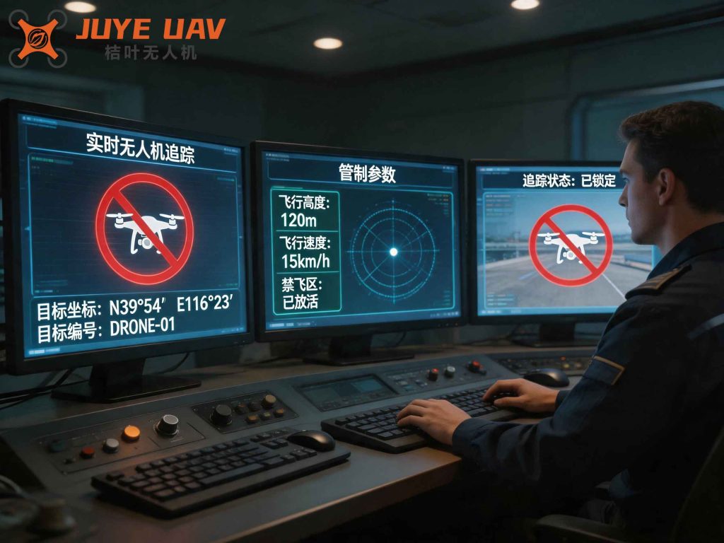
Below is an illustration of the system architecture, showing how the detection and disposal subsystems are networked to the command center.
Protection Strategy for Power Substations
An effective drone regulation strategy must be adaptive and multi-layered. I have developed a protection strategy based on three zones: safe zone, warning zone, and prohibited zone. The strategy flow is depicted conceptually by the following steps:
- Continuous Spectrum Scanning: The RF sensor continuously scans the entire frequency band (e.g., 800 MHz to 6 GHz). When a known drone control signal is detected, the system logs its frequency and signal strength.
- Target Tracking: Using radar and RF angle-of-arrival, the system computes the real-time trajectory of the drone. The Kalman filter is applied to smooth the tracking data. The state update equation is:
$$x_{k+1} = F x_k + B u_k + w_k$$
where \(x_k\) is the state vector (position, velocity), \(F\) is the transition matrix, \(u_k\) is the control input, and \(w_k\) is process noise. This allows accurate prediction of the drone’s future path.
- Threat Assessment: If the drone is heading towards the substation and its speed is above a threshold, the system classifies it as a high-priority threat.
- Countermeasure Activation: When the drone crosses the prohibited boundary, the jammer is triggered. To avoid interfering with substation GPS timing equipment, the jamming only blocks the flight control channel (2.4 GHz/5.8 GHz) while leaving GPS/BeiDou signals untouched. The jamming is operated in short bursts (e.g., 3 seconds) to minimize electromagnetic pollution.
- Post-Engagement Verification: After jamming, the detection subsystem re-scans to confirm that the drone has either landed, returned, or lost power. If the drone remains, the jamming cycle repeats or escalates to a higher power level.
Three primary jamming modes are available:
- Control link blocking (2.4/5.8 GHz): Causes the drone to lose command; if GPS is available, it may return home; otherwise it hovers or lands.
- GPS blocking (1.15–1.65 GHz): Disturbs navigation but leaves manual control functional; however, this mode is avoided in substations due to potential interference with GPS time synchronization equipment.
- Combined block: Blocks both control and GPS, leading to loss of control and potential crash. This mode is used only as a last resort.
The power density required for effective jamming can be calculated using the link budget:
$$P_{jam} \geq P_{rx} + \text{J/S} + G_{jam} – G_{rx} + L_{path}$$
where \(P_{rx}\) is the received power from the legitimate controller, J/S is the required jammer-to-signal ratio (typically 10 dB), \(G_{jam}\) and \(G_{rx}\) are antenna gains, and \(L_{path}\) is the path loss. By setting appropriate thresholds, the system ensures reliable neutralization while minimizing false positives.
Conclusion
In this study, I have presented a comprehensive drone regulation and control system tailored for critical power infrastructure. By integrating multiple detection technologies (radar, RF spectrum, optical) and employing a carefully designed jamming strategy, the system provides a robust defense against unauthorized UAV incursions. The distributed architecture ensures scalability and easy integration with existing security systems. The mathematical models for detection range, localization accuracy, and jamming effectiveness provide a solid theoretical foundation. This system not only enhances the security of unattended substations but also contributes to the broader goal of drone regulation in sensitive areas. Future work will focus on adaptive algorithms to counter evolving drone threats, such as autonomous swarms and frequency-hopping communication. The implementation of such a system will significantly reduce operational risks and ensure the reliability of power supply in the face of growing aerial challenges.