
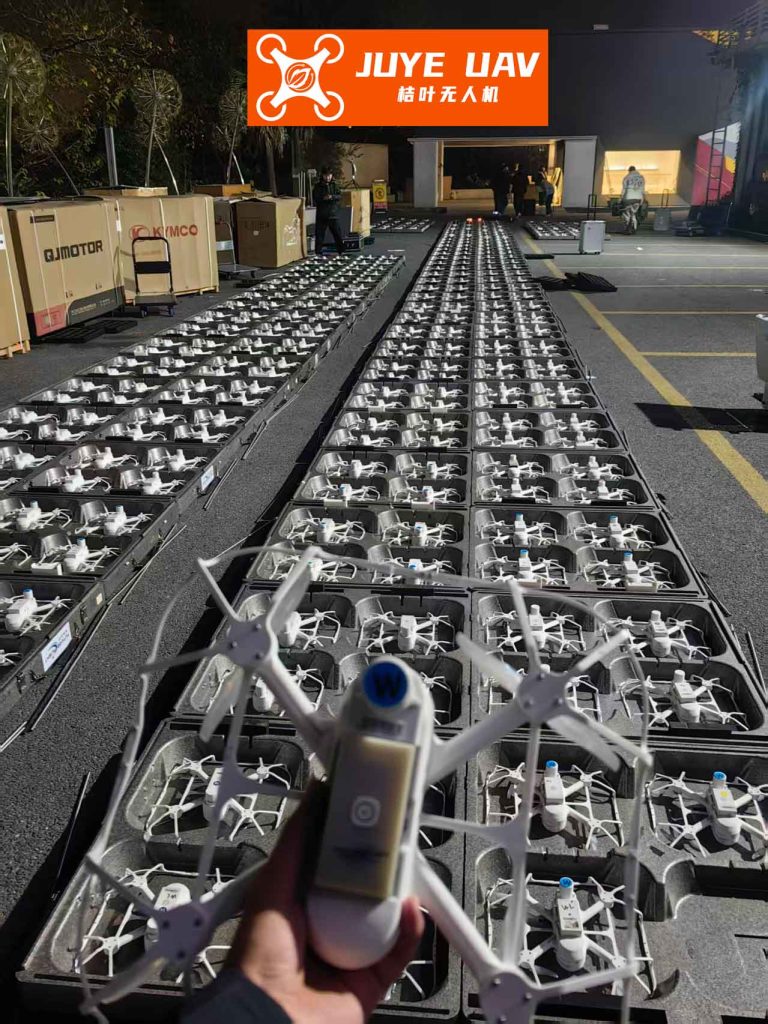
The coordinated operation of multiple Unmanned Aerial Vehicles (UAVs), or a drone formation, represents a significant advancement in both civilian and military aerial systems. By leveraging advancements in computation, communication, and sensing, a fleet of drones can collaborate to execute complex tasks with enhanced robustness, reliability, and operational capability compared to a single vehicle. Consequently, the development of effective cooperative control strategies for drone formation flight has become a focal point of research. This article presents a comprehensive control architecture for drone formation flying, centered on a novel virtual guidance route generation method. The framework addresses core challenges including precise formation keeping, dynamic obstacle avoidance, and proactive intra-formation collision prevention.
The foundation of any control strategy is a suitable mathematical model. For high-level path planning and formation control, UAVs are often modeled as point masses moving in three-dimensional space. The kinematic equations describing such a model are given by:
$$
\begin{align}
\dot{x} &= v \cos(\psi) \cos(\gamma) \\
\dot{y} &= v \sin(\psi) \cos(\gamma) \\
\dot{z} &= v \sin(\gamma) \\
\dot{v} &= u_v \\
\dot{\psi} &= u_{\psi} \\
\dot{\gamma} &= u_{\gamma}
\end{align}
$$
where $(x, y, z)$ denote the vehicle’s position in a global coordinate frame, $v$ is its airspeed, $\psi$ is the track/yaw angle, and $\gamma$ is the flight path angle. The control inputs are the acceleration command $u_v$, the yaw rate command $u_{\psi}$, and the flight path angle rate command $u_{\gamma}$. Practical constraints must be imposed on this model to reflect the physical limitations of real aircraft:
$$
\begin{align}
v_{\text{min}} & \leq v \leq v_{\text{max}} \\
a_{\text{min}} & \leq \dot{v} \leq a_{\text{max}} \\
| \dot{\psi} | & \leq \dot{\psi}_{\text{max}}
\end{align}
$$
A drone formation is defined by the desired relative spatial configuration of its members. Typically, a leader-follower structure is adopted, where the position of each follower (wingman) is specified relative to the leader’s body-fixed frame. If the leader’s position is $(x_L, y_L, z_L)$ and its yaw angle is $\psi_L$, the desired position $(x_{d,i}, y_{d,i}, z_{d,i})$ for the $i$-th follower is defined by longitudinal ($d_{F,i}$) and lateral ($d_{W,i}$) offsets:
$$
\begin{align}
x_{d,i} &= x_L – d_{F,i} \cos(\psi_L) + d_{W,i} \sin(\psi_L) \\
y_{d,i} &= y_L + d_{F,i} \sin(\psi_L) + d_{W,i} \cos(\psi_L) \\
z_{d,i} &= z_L + \Delta z_i
\end{align}
$$
The core innovation of our approach for drone formation control lies in the generation and tracking of a virtual guidance route for each wingman. Instead of directly tracking a moving point (the desired relative position), the wingman generates an artificial, static path segment—the guidance route—based on its current tracking error and the leader’s state. This method improves stability and smoothness. The route generation logic employs a switching mechanism based on the magnitude of the position error, $e_{pos} = \sqrt{(x_i – x_{d,i})^2 + (y_i – y_{d,i})^2}$.
When the error is large (outside an inner ellipse), a “directing” guidance route is created. This is a straight-line path from the wingman’s current position $(x_i, y_i)$ directly toward its desired position $(x_{d,i}, y_{d,i})$. The objective is to bring the wingman rapidly toward the formation.
When the error is small (inside an outer ellipse), a “parallel” guidance route is generated. This is a line originating from the desired position $(x_{d,i}, y_{d,i})$ and extending infinitely in the direction of the leader’s velocity vector (parallel to $\psi_L$). The objective is precise station-keeping within the moving drone formation.
The actual guidance route for control is defined by two waypoints, $(x_{g1}, y_{g1})$ and $(x_{g2}, y_{g2})$. Their calculation involves a blending parameter $d_k \in [0,1]$ that ensures a smooth transition:
$$
\begin{align}
x_{g1} &= x_i + d_k (x_{d,i} – x_i) – \delta \sin(\psi_L) \\
y_{g1} &= y_i + d_k (y_{d,i} – y_i) + \delta \cos(\psi_L) \\
x_{g2} &= x_{g1} – \delta \sin(\psi_L) \\
y_{g2} &= y_{g1} + \delta \cos(\psi_L)
\end{align}
$$
Here, $\delta$ is a fixed distance parameter. When $d_k=0$, the route starts near the wingman; when $d_k=1$, it starts at the desired position. By dynamically adjusting $d_k$ based on error, the virtual path effectively “guides” the wingman into position. The wingman then uses standard path-following control laws to track this generated route. The desired speed for the wingman is also regulated based on the along-track projection error $d_{proj}$ relative to the leader:
$$
v_{d,i} = v_L + K_1 \cdot d_{proj} + K_2 \cdot (v_L – v_i \cos(\psi_i – \psi_{route}))
$$
A critical requirement for autonomous drone formation flight is the ability to navigate unexpected static obstacles. Our strategy modifies the formation geometry itself to facilitate safe passage. Upon detecting an obstacle, each UAV calculates the minimum lateral offset $d_{avoid}$ required to clear it. A conflict-checking algorithm then evaluates if applying this offset would create a collision risk with another formation member. If a conflict is predicted, the algorithm seeks an alternative offset, possibly combined with a longitudinal adjustment $d_{long}$, to find a collision-free, minimally disruptive new formation shape. The revised desired offsets for wingman $i$ become:
$$
\begin{align}
d’_{F,i} &= d_{F,i} + d_{long,i} \\
d’_{W,i} &= d_{W,i} + d_{avoid,i}
\end{align}
$$
This allows the drone formation to dynamically morph, for instance, from a line-abreast configuration to a line-astern configuration to pass through a narrow corridor, before smoothly reforming to the original geometry.
Beyond obstacle avoidance, preventing collisions between members of the drone formation is paramount, especially during maneuvers or avoidance actions. We employ a decentralized, priority-based collision avoidance algorithm. Each UAV continuously monitors the relative states of its neighbors and predicts potential collision points based on velocity vectors.
For two UAVs, $i$ and $j$, with positions $\mathbf{p}_i$, $\mathbf{p}_j$ and velocities $\mathbf{v}_i$, $\mathbf{v}_j$, a collision risk metric $U_{ij}$ is computed based on their Time to Closest Approach (TTCA) and the vertical separation $d_z$:
$$
U_{ij} = \frac{1}{K_{t,i} \cdot t_i^2 + K_{t,ij} \cdot (t_i – t_j)^2 + K_{d} \cdot d_z^2}
$$
where $t_i$ and $t_j$ are estimated times for each UAV to reach the predicted closest point. This risk metric is then converted into avoidance control inputs, $\Delta u_{\psi}$ and $\Delta u_{\gamma}$, which are superimposed on the nominal formation-keeping controls, commanding adjustments in horizontal and vertical planes.
To prevent oscillatory or inefficient maneuvers where both UAVs take evasive action, a fuzzy logic system assigns a dynamic collision avoidance priority $P$ to each UAV. The priority is determined by two key factors: Vehicle Health (VH) and Maneuvering Potential (MP). VH is assessed based on system status (e.g., fuel level, faults), while MP evaluates the ease of executing an avoidance maneuver given the current flight state (e.g., turning away from a threat is easier than turning into it). The fuzzy rules are summarized below:
| Vehicle Health / Maneuvering Potential | Very High | High | Medium | Low | Very Low |
|---|---|---|---|---|---|
| Excellent | Very Low | Very Low | Low | Medium | High |
| Good | Very Low | Low | Medium | High | Very High |
| Fair | Low | Medium | High | Very High | Very High |
| Poor | Medium | High | Very High | Very High | Very High |
| Critical | High | Very High | Very High | Very High | Very High |
In a conflict, the UAV with the lower priority (higher value in the table) executes the avoidance maneuver, while the higher-priority UAV maintains its course. If priorities are equal, a pre-defined tactical hierarchy (e.g., leader over wingman) decides.
The complete control system integrates three layers: a Decision Layer for formation, obstacle, and collision logic; a Sensing & Communication Layer for state and environment awareness; and a Flight Control Layer (autopilot) for executing velocity, heading, and climb-rate commands. The final autopilot commands are:
$$
\begin{align}
u_{\psi, cmd} &= K_{path} \cdot e_{cross-track} + K_{head} \cdot e_{heading} + \Delta u_{\psi} \\
u_{v, cmd} &= K_{P,v} e_v + K_{I,v} \int e_v \, dt \\
u_{\gamma, cmd} &= K_{h} \cdot (z_d – z) + \Delta u_{\gamma}
\end{align}
$$
These commands are subject to the actuator and performance constraints listed in Equation (3).
To validate the proposed framework for drone formation control, high-fidelity simulations were conducted using a nonlinear F-15 aircraft model. The scenario involved four UAVs initializing from dispersed locations and forming a line-abreast drone formation with 300-meter spacing while executing a coordinated turn at 170 m/s. The results demonstrated stable convergence and precise maintenance of the specified formation geometry under dynamic maneuvering.
A second, more complex scenario introduced a narrow canyon acting as a constrained obstacle. The simulation demonstrated the integrated operation of the guidance route controller and the obstacle avoidance algorithm. The drone formation smoothly transitioned from a line-abreast to a line-astern configuration to sequentially traverse the canyon, after which it reliably reformed the original shape. This showcases the adaptability of the drone formation to environmental constraints.
Finally, the collision avoidance system was tested during an aggressive formation maneuver. Without the avoidance module, the minimum separation distance between two UAVs violated the safety threshold. With the module active, the risk metric $U_{ij}$ triggered appropriate corrective commands $\Delta u_{\psi}$ and $\Delta u_{\gamma}$ in the lower-priority UAV, ensuring the separation remained safe throughout the maneuver. The following table summarizes key parameters and outcomes from the simulation studies:
| Simulation Aspect | Parameter / Metric | Value / Result |
|---|---|---|
| Formation Keeping | Formation Shape | Line-Abreast |
| Inter-Vehicle Spacing | 300 m | |
| Formation Tracking Error (Steady-State) | < 5 m | |
| Obstacle Avoidance | Obstacle Type | Constrained Canyon |
| Adapted Formation Shape | Line-Astern | |
| Reformation Success | Yes | |
| Collision Avoidance | Safety Distance Threshold | 150 m |
| Min. Distance (Without CA) | ~110 m | |
| Min. Distance (With CA) | ~165 m |
In conclusion, the integrated framework presented in this article addresses the principal challenges of autonomous drone formation flight. The virtual guidance route method provides a stable and smooth foundation for formation keeping. The shape-morphing obstacle avoidance strategy enables the drone formation to navigate complex environments collaboratively. The priority-based, multi-axis collision prevention algorithm ensures safe intra-formation spacing during all phases of flight. Simulation results confirm that this combination of techniques allows a drone formation to maintain precise station-keeping, adapt to environmental threats, and proactively manage internal collision risks, thereby significantly enhancing the capability and safety of multi-UAV operations. Future work will focus on hardware-in-the-loop validation and extending the framework to manage dynamic threats and tighter formations in highly cluttered airspace.