
The emergence and rapid evolution of autonomous drone systems represent one of the most transformative technological advancements of our era. While individual drones offer remarkable capabilities, the true frontier of their potential is unlocked through coordinated collective behavior—the domain of drone formation. My exploration into this field is driven by a fundamental belief: the synergy of multiple simple agents can yield intelligence and performance far surpassing that of a single, complex entity. This principle underpins my research and guides my investigation into the models, strategies, and challenges that define sophisticated drone formation systems. From precise agricultural monitoring to complex search-and-rescue operations and mesmerizing aerial displays, the applications are as diverse as they are impactful. This article synthesizes my perspective on the core pillars of drone formation, focusing on the mathematical formalisms, control architectures, and enabling technologies that make these aerial collectives not just possible, but robust and scalable.
The cornerstone of any drone formation study is a rigorous dynamic model. I consider a formation of N homogeneous drones. The kinematic and dynamic model for the i-th drone can be represented in a unified framework. Typically, we model each agent as a point mass or a rigid body with simplified dynamics. A common second-order model in a two-dimensional plane is given by:
$$ \dot{p}_i = v_i $$
$$ \dot{v}_i = u_i – \zeta v_i $$
where \( p_i \in \mathbb{R}^2 \) is the position vector, \( v_i \in \mathbb{R}^2 \) is the velocity vector, \( u_i \in \mathbb{R}^2 \) is the control input (acceleration), and \( \zeta \) is a damping coefficient. For three-dimensional formations involving altitude and more complex attitudes, the state space expands. A common 3D translational model, often decoupled from attitude dynamics via an inner-loop controller, is:
$$ \ddot{x}_i = a_{x,i}, \quad \ddot{y}_i = a_{y,i}, \quad \ddot{z}_i = a_{z,i} $$
Here, \( (x_i, y_i, z_i) \) denote the inertial coordinates and \( (a_{x,i}, a_{y,i}, a_{z,i}) \) are the commanded accelerations. The collective state of the entire drone formation is the aggregation of all individual states: \( \mathbf{P} = [p_1^T, …, p_N^T]^T \) and \( \mathbf{V} = [v_1^T, …, v_N^T]^T \). The geometry of the drone formation is defined not by absolute positions but by relative vectors. A desired formation is specified by a set of relative displacement vectors \( \delta_{ij} \) for a subset of neighbor pairs (i, j):
$$ p_i(t) – p_j(t) \rightarrow \delta_{ij} \quad \forall (i,j) \in \mathcal{E} $$
where \( \mathcal{E} \) defines the formation graph’s edge set. This relative specification provides invariance to global translation and rotation, which is a critical feature for maneuvering drone formation groups.
| Modeling Aspect | Typical Formulation | Key Parameters/Variables | Considerations for Formation |
|---|---|---|---|
| Kinematics | $$ \dot{p}_i = v_i $$ | \( p_i \): Position; \( v_i \): Velocity | Defines the basis for relative state errors. |
| Dynamics (2D Simplified) | $$ \dot{v}_i = u_i – \zeta v_i $$ | \( u_i \): Control input; \( \zeta \): Damping | Captures essential response; good for high-level design. |
| Dynamics (3D Decoupled) | $$ \ddot{\mathbf{r}}_i = \mathbf{a}_i $$ | \( \mathbf{r}_i = (x_i, y_i, z_i) \); \( \mathbf{a}_i \): Commanded acceleration | Enables separate position control; relies on stable inner loops. |
| Formation Specification | $$ p_i – p_j \rightarrow \delta_{ij} $$ | \( \delta_{ij} \): Desired relative displacement | Encodes shape; graph \( \mathcal{E} \) defines sensing/comm structure. |
The control problem for a drone formation is to design the input laws \( u_i \) that achieve and maintain the desired formation geometry, ensure stability, and enable coordinated motion. My approach often revolves around decentralized or distributed control laws, where each drone’s control signal depends only on information from its neighbors in the formation graph. A seminal and highly influential strategy is the consensus-based or distributed averaging approach. The fundamental idea is to drive the states of all agents to a common agreement. For formation control, we modify this to achieve consensus on relative states. A basic consensus algorithm for velocity alignment in a drone formation is:
$$ u_i^{consensus} = – \sum_{j \in \mathcal{N}_i} (v_i – v_j) $$
where \( \mathcal{N}_i \) is the set of neighbors of drone i. To achieve a static formation, we combine this with a term that regulates position errors relative to neighbors:
$$ u_i = – \sum_{j \in \mathcal{N}_i} \left[ k_p (p_i – p_j – \delta_{ij}) + k_v (v_i – v_j) \right] $$
Here, \( k_p > 0 \) and \( k_v > 0 \) are control gains. This is a classic linear distributed protocol. For a maneuvering drone formation, where the entire group must follow a desired trajectory \( p_0(t) \) with velocity \( v_0(t) \), at least one agent (the leader) must have access to this global information. The control law for a leader-follower configuration can be structured as follows. For the leader (e.g., drone 1):
$$ u_1 = \dot{v}_0 – k_{p1}(p_1 – p_0) – k_{v1}(v_1 – v_0) $$
For a follower drone i:
$$ u_i = – \sum_{j \in \mathcal{N}_i} \left[ k_p (p_i – p_j – \delta_{ij}) + k_v (v_i – v_j) \right] $$
In this setup, the follower drones maintain the formation shape relative to each other and, through the interconnection graph, ultimately relative to the leader. The stability of such interconnected systems is typically analyzed using Lyapunov methods or by examining the eigenvalues of the composite system matrix derived from the graph Laplacian \( \mathcal{L} \). The closed-loop dynamics for the relative error in a linear formation control system often take the form:
$$ \dot{\mathbf{e}} = (\mathbf{I}_N \otimes \mathbf{A} – \mathcal{L} \otimes \mathbf{BK}) \mathbf{e} $$
where \( \mathbf{e} \) is the stacked error vector, \( \mathbf{A} \) and \( \mathbf{B} \) are state and input matrices from the individual drone model, \( \mathbf{K} \) is the control gain matrix, and \( \otimes \) denotes the Kronecker product. The properties of the graph Laplacian \( \mathcal{L} \) directly determine the stability of the drone formation.
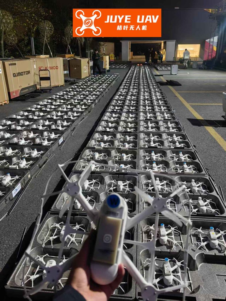
A critical application that vividly demonstrates the precision and scalability of modern drone formation technology is the coordinated aerial light show. Here, hundreds or even thousands of drones act as flying pixels, forming complex, dynamic three-dimensional images in the night sky. This application pushes the boundaries of several key formation challenges: ultra-precise relative positioning (often using RTK-GNSS), minimal communication latency for synchronized motion updates, and robust safety protocols to prevent mid-air collisions. The desired formation shape \( \{\delta_{ij}(t)\} \) is now a time-varying sequence, pre-computed and distributed to the fleet. The control must be exceptionally reliable, as a single failure could disrupt the entire visual spectacle. This domain stands as a powerful testament to how far the practical implementation of large-scale drone formation systems has progressed.
| Control Strategy | Typical Control Law (for drone i) | Key Characteristics | Best Suited For |
|---|---|---|---|
| Distributed Consensus | $$ u_i = -\sum_{j \in N_i} [k_p (p_i-p_j-\delta_{ij}) + k_v (v_i-v_j)] $$ | Fully decentralized; uses only neighbor info; graph connectivity crucial. | Static or slow-moving shapes; resilient networks. |
| Leader-Follower | Leader: Has global trajectory info. Followers: Use neighbor-relativ e laws. |
Hierarchical; simpler follower logic; single point of failure (leader). | Maneuvering formations; predefined paths. |
| Virtual Structure | Each drone tracks a point on a moving rigid virtual body. | Centralized planning; very precise shape keeping; less flexible. | Highly rigid drone formation patterns (e.g., light shows). |
| Behavior-Based | $$ u_i = \sum_k \beta_k f_k(\text{state, neighbors}) $$ | Combines objectives (avoidance, cohesion, alignment); emergent behavior. | Dynamic environments (e.g., obstacle fields). |
No discussion of drone formation is complete without addressing the critical enabler: communication and coordination. The performance and even the stability of the formation are intimately tied to the underlying network. The formation graph \( \mathcal{G} = (\mathcal{V}, \mathcal{E}) \) defines who can sense or communicate with whom. Key parameters include update rates, communication delays, packet loss, and bandwidth constraints. A delayed signal can destabilize an otherwise stable control law. If we model a constant delay \( \tau \) in the state information received from neighbors, the control law becomes:
$$ u_i(t) = – \sum_{j \in \mathcal{N}_i} \left[ k_p (p_i(t) – p_j(t-\tau) – \delta_{ij}) + k_v (v_i(t) – v_j(t-\tau)) \right] $$
The stability analysis must then account for this delay, often leading to upper bounds on permissible \( \tau \) for given control gains. Furthermore, in many real-world scenarios, continuous communication is neither feasible nor desirable. This has led me to investigate event-triggered control strategies for drone formation, where a drone broadcasts its state to neighbors only when a local error threshold is exceeded. The triggering condition for drone i might be:
$$ \| e_i(t) \| = \| \hat{x}_i(t) – x_i(t) \| > c \| z_i(t) \| $$
where \( \hat{x}_i \) is the last broadcast state, \( x_i \) is the current state, \( z_i \) is a function of neighbor information, and \( c > 0 \) is a design parameter. This can significantly reduce communication load while preserving formation stability.
Beyond communication, relative sensing—using onboard cameras, LiDAR, or UWB ranging—is a vital alternative or supplement. This leads to the problem of bearing-based or distance-based formation control. In a distance-based approach, the control objective is to stabilize the set of inter-agent distances \( \| p_i – p_j \| \) to desired values \( d_{ij} \), without directly controlling the relative vectors’ orientation. The corresponding control law is inherently nonlinear:
$$ u_i = – \sum_{j \in \mathcal{N}_i} ( \| p_{ij} \|^2 – d_{ij}^2 ) p_{ij} $$
where \( p_{ij} = p_i – p_j \). The stability and rigidity of such a drone formation depend on the graph’s infinitesimal rigidity property.
| Coordination Modality | Key Principle | Advantages | Challenges & Considerations |
|---|---|---|---|
| Centralized Communication | All drones link to a central ground station. | Simple architecture; global optimization possible. | Single point of failure; limited scalability; latency. |
| Distributed Ad-hoc Networking | Drones relay data peer-to-peer (mesh network). | Robust to single failures; scalable; enables decentralization. | Network management complex; latency varies; requires routing protocols. |
| Relative Sensing (Vision/LiDAR) | Onboard sensors measure neighbor states directly. | No communication needed; high relative precision. | Line-of-sight required; sensor range limited; data association needed. |
| Event-Triggered Control | Transmit data only when a local error is large. | Drastically reduces communication load and energy use. | Complex stability analysis; risk of Zeno behavior. |
The real-world efficacy of a drone formation is ultimately tested by its ability to handle disturbances, model uncertainties, and agent failures. Robust and adaptive control methods are therefore essential. A common approach is to model external disturbances (like wind gusts) as bounded unknown inputs \( d_i(t) \) to the dynamics: \( \dot{v}_i = u_i + d_i \). A robust control law might incorporate a sliding mode component:
$$ u_i = u_{i,nom} – \rho \, \text{sign}(s_i) $$
where \( u_{i,nom} \) is a nominal formation-keeping control, \( s_i \) is a sliding surface (e.g., a combination of position and velocity error), and \( \rho \) is a gain chosen to overcome the bound of \( d_i \). This ensures the formation errors remain within a prescribed boundary despite disturbances. For long-term operations or systems with varying parameters, adaptive control can be integrated. For instance, if the damping coefficient \( \zeta_i \) is unknown, an adaptive estimator can be employed online:
$$ \dot{\hat{\zeta}}_i = \gamma v_i^T (v_i \hat{\zeta}_i – u_i + u_{i,form}) $$
where \( \hat{\zeta}_i \) is the estimate, \( \gamma > 0 \) is an adaptation gain, and \( u_{i,form} \) is the formation control part of the input. This allows the drone formation to maintain performance despite parametric uncertainties.
Looking forward, the challenges and opportunities for drone formation systems are immense. Scalability to thousands of agents, resilient operation in GPS-denied environments, and fully autonomous decision-making in complex dynamic scenarios are active research frontiers. The integration of machine learning for formation shape optimization, obstacle negotiation, and fault recovery is a particularly promising direction. A learning-based policy might seek to minimize a global cost function \( J \) for the drone formation over time:
$$ J = \int_0^T \left( \sum_i \| u_i \|^2 + \sum_{(i,j)\in\mathcal{E}} \| p_i – p_j – \delta_{ij} \|^2 \right) dt $$
and be trained using reinforcement learning or imitation learning. Furthermore, the heterogeneous drone formation, comprising agents with different capabilities (e.g., sensor payloads, endurance, mobility), opens new avenues for mission-specific optimization. In conclusion, my journey in studying drone formation systems has reinforced the view that they are more than just a collection of flying robots. They are a paradigm for distributed intelligence, a testbed for advanced control theory, and a powerful tool whose potential applications are only beginning to be explored. The mathematical elegance of their description, combined with the sheer visual impact of their operation, makes the study of drone formation one of the most compelling and multidisciplinary endeavors in modern engineering.