
The operational efficacy of unmanned aerial vehicles (UAVs) is significantly amplified when they operate not as singular units but as cohesive, coordinated groups. The paradigm of drone formation flight presents substantial advantages over solo missions, including enhanced task capability through role distribution, increased system robustness via redundancy, and improved mission efficiency. However, the core challenge lies in developing decentralized control laws that enable a group of drones to autonomously achieve and maintain a desired geometric configuration while potentially maneuvering. This document details the comprehensive design of a coordination control algorithm for drone formation keeping, coupled with its practical implementation and visualization within a 3D simulation environment. The integration of these two facets—theoretical control design and practical 3D visualization—provides a robust framework for developing and testing advanced multi-agent aerial systems.
The foundation for modeling the relative motion within a drone formation operating in close proximity is often based on linearized equations. For near-Earth orbital or high-altitude flight scenarios, the Clohessy-Wiltshire (C-W) equations provide a suitable approximation. These equations describe the relative dynamics of a chaser vehicle with respect to a target moving on a circular reference orbit. Defining the state vector for the i-th drone’s error relative to its desired state as \(\mathbf{\tilde{X}}_i = [\tilde{x}, \tilde{y}, \tilde{z}, \dot{\tilde{x}}, \dot{\tilde{y}}, \dot{\tilde{z}}]^T\), the linearized error dynamics can be expressed in state-space form:
$$
\mathbf{\dot{\tilde{X}}}_i = \mathbf{A} \mathbf{\tilde{X}}_i + \mathbf{B} \mathbf{U}_i, \quad \mathbf{\tilde{Y}}_i = \mathbf{C} \mathbf{\tilde{X}}_i
$$
where the system matrices for a reference orbit with angular rate \(\omega\) are:
$$
\mathbf{A} = \begin{bmatrix}
0 & 0 & 0 & 1 & 0 & 0 \\
0 & 0 & 0 & 0 & 1 & 0 \\
0 & 0 & 0 & 0 & 0 & 1 \\
3\omega^2 & 0 & 0 & 0 & 2\omega & 0 \\
0 & 0 & 0 & -2\omega & 0 & 0 \\
0 & 0 & -\omega^2 & 0 & 0 & 0
\end{bmatrix}, \quad
\mathbf{B} = \begin{bmatrix}
0 & 0 & 0 \\
0 & 0 & 0 \\
0 & 0 & 0 \\
1 & 0 & 0 \\
0 & 1 & 0 \\
0 & 0 & 1
\end{bmatrix}, \quad
\mathbf{C} = \begin{bmatrix}
1 & 0 & 0 & 0 & 0 & 0 \\
0 & 1 & 0 & 0 & 0 & 0 \\
0 & 0 & 1 & 0 & 0 & 0
\end{bmatrix}
$$
The control objective for the drone formation is to design a distributed controller \(\mathbf{U}_i\) such that the state error \(\mathbf{\tilde{X}}_i\) for all drones converges to zero, ensuring the actual formation tracks the desired one. This must be achieved using only local information and information exchanged between neighboring drones according to a communication topology.
The communication network within the drone formation is modeled as an undirected graph \(\mathcal{G} = (\mathcal{V}, \mathcal{E}, \mathcal{A})\), where \(\mathcal{V}=\{1,2,…,N\}\) represents the drones, \(\mathcal{E} \subseteq \mathcal{V} \times \mathcal{V}\) represents the communication links, and \(\mathcal{A}=[a_{ij}]\) is the weighted adjacency matrix. The Laplacian matrix \(\mathbf{L}\) of the graph, which encodes the connectivity structure, is defined as \(\mathbf{L} = \mathbf{D} – \mathcal{A}\), where \(\mathbf{D}\) is the diagonal degree matrix. The stability and convergence properties of the formation heavily depend on the eigenvalues of \(\mathbf{L}\).
| Graph Parameter | Symbol | Description |
|---|---|---|
| Number of Agents | \(N\) | Total number of drones in the formation. |
| Adjacency Matrix | \(\mathcal{A}\) | \(a_{ij}>0\) if drones \(i\) and \(j\) communicate, else \(a_{ij}=0\). |
| Laplacian Matrix | \(\mathbf{L}\) | \(\mathbf{L}=\mathbf{D}-\mathcal{A}\). Key matrix for consensus analysis. |
| Second Smallest Eigenvalue | \(\lambda_2(\mathbf{L})\) | Algebraic connectivity. Governs the convergence speed of consensus. |
The proposed controller for the i-th drone in the drone formation is a composite full-state feedback law structured on the consensus principle. It consists of two main components: a local stabilization term and a neighbor coordination term.
$$
\mathbf{U}_i = \mathbf{U}_{i}^{local} + \mathbf{U}_{i}^{coord} = -\mathbf{K}_1 \mathbf{\tilde{X}}_i – \mathbf{K}_2 \sum_{j \in \mathcal{N}_i} a_{ij} (\mathbf{\tilde{X}}_i – \mathbf{\tilde{X}}_j)
$$
Here, \(\mathbf{K}_1 \in \mathbb{R}^{3 \times 6}\) is the local feedback gain matrix designed to stabilize the individual drone’s error dynamics (i.e., make matrix \(\mathbf{A} – \mathbf{B}\mathbf{K}_1\) Hurwitz). The matrix \(\mathbf{K}_2 \in \mathbb{R}^{3 \times 6}\) is the coordination gain matrix, which uses the weighted sum of state differences with neighbors to drive the entire drone formation towards consensus on the error state, thereby achieving formation keeping.
The closed-loop dynamics for the entire multi-agent system can be analyzed by stacking the states of all drones. Defining the global error state vector \(\mathbf{\tilde{X}} = [\mathbf{\tilde{X}}_1^T, \mathbf{\tilde{X}}_2^T, …, \mathbf{\tilde{X}}_N^T]^T\), the collective dynamics are:
$$
\mathbf{\dot{\tilde{X}}} = [\mathbf{I}_N \otimes (\mathbf{A} – \mathbf{B}\mathbf{K}_1) – \mathbf{L} \otimes (\mathbf{B}\mathbf{K}_2)] \mathbf{\tilde{X}}
$$
where \(\otimes\) denotes the Kronecker product. The stability of this large-scale system hinges on the eigenvalues of the matrix \(\mathbf{I}_N \otimes (\mathbf{A} – \mathbf{B}\mathbf{K}_1) – \mathbf{L} \otimes (\mathbf{B}\mathbf{K}_2)\). A fundamental result in consensus theory states that the system achieves formation keeping if and only if all the matrices \(\mathbf{A} – \mathbf{B}\mathbf{K}_1 – \lambda_i \mathbf{B}\mathbf{K}_2\) are Hurwitz for every non-zero eigenvalue \(\lambda_i\) of the Laplacian matrix \(\mathbf{L}\). This separation principle allows for the systematic design of \(\mathbf{K}_1\) for single-agent stability and \(\mathbf{K}_2\) to handle the inter-agent coordination dictated by the communication graph.
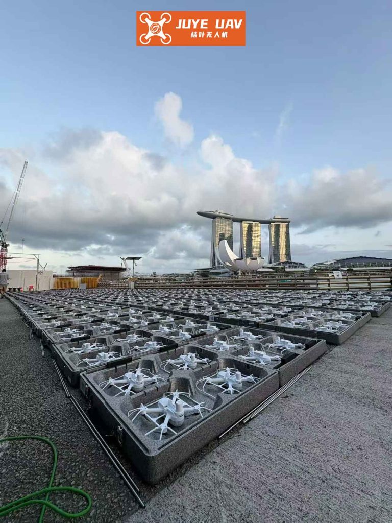
A critical component for the realistic simulation and evaluation of any drone formation control algorithm is an effective 3D visualization system. Moving beyond simple point or primitive representations, the integration of detailed 3D models significantly enhances situational awareness, provides intuitive visual feedback on formation geometry and orientation, and allows for more effective analysis of complex maneuvers. The implementation involves two primary stages: model asset preparation and real-time rendering integration.
The workflow begins with the creation of 3D drone models using specialized software such as Blender, 3ds Max, or Maya. These models are textured and rigged if necessary. For efficient parsing and loading in a real-time application, the model is exported to a widely supported, lightweight format. The 3DS file format, while somewhat legacy, offers a straightforward binary structure ideal for demonstration. Key model data is stored in hierarchical chunks:
| Chunk ID | Description | Contains |
|---|---|---|
| 0x4D4D | Main Chunk | Entire file container. |
| 0x3D3D | 3D Editor Chunk | All mesh and object data. |
| 0x4000 | Object Block | Name and data for a single 3D object. |
| 0x4100 | Triangular Mesh | Vertex lists, face lists, mapping coordinates. |
| 0xAFFF | Material Block | Material names, textures, colors. |
A custom parser is developed to traverse this chunk hierarchy, extracting vertex positions, face indices, texture coordinates, and material information. This parsed data is then used to construct buffers compatible with a graphics API like OpenGL or DirectX. Each drone in the simulation is associated with an instance of this model data. The real-time rendering engine, typically part of a 3D mapping or simulation platform, is responsible for drawing each model instance at its current world position and attitude, which are continuously updated by the drone formation control algorithm. The transformation from the drone’s local navigation frame (e.g., North-East-Down or Earth-Centered Earth-Fixed) to the 3D viewport is computed per frame:
$$
\mathbf{M}_{model}^{view} = \mathbf{M}_{view} \times \mathbf{M}_{world} \times \mathbf{T}(x,y,z) \times \mathbf{R}(\psi, \theta, \phi) \times \mathbf{M}_{local}
$$
Where \(\mathbf{T}\) and \(\mathbf{R}\) are the translation and rotation matrices derived from the drone’s simulated position \((x, y, z)\) and orientation (yaw \(\psi\), pitch \(\theta\), roll \(\phi\)), \(\mathbf{M}_{local}\) is the model’s local origin adjustment, \(\mathbf{M}_{world}\) is the geospatial transformation, and \(\mathbf{M}_{view}\) is the camera view matrix.
| Rendering Stage | OpenGL Equivalent | Purpose |
|---|---|---|
| Vertex Processing | Vertex Shader | Transforms 3D model vertices to 2D screen space using the \(\mathbf{M}_{model}^{view}\) matrix. |
| Rasterization | Fixed-Function | Converts transformed primitives (triangles) into fragments (pixels). |
| Fragment Processing | Fragment Shader | Determines the final color of each fragment using texture and lighting data. |
| Output Merging | Blending/Depth Test | Combines fragment colors with the framebuffer, handling transparency and occlusions. |
To validate the drone formation control algorithm and the 3D visualization module, a co-simulation framework is established. The control algorithm is implemented in a numerical computing environment (e.g., MATLAB/Simulink) which solves the differential equations of motion for each drone in real-time or faster-than-real-time. At every simulation time step, the computed states (latitude, longitude, altitude, attitude) for all drones in the drone formation are packetized and transmitted via a communication protocol (e.g., UDP) to the 3D visualization application.
The visualization application, built upon a 3D geospatial engine, listens for this data stream. Upon receiving a state packet, it updates the corresponding 3D drone model’s position and orientation in the virtual world. The engine renders the terrain from Digital Elevation Models (DEM) and imagery from Digital Orthophoto Maps (DOM), over which the detailed drone models are drawn, providing a geographically contextualized view of the drone formation‘s operation.
A canonical simulation scenario involves a three-drone formation. The initial desired formation is a circular configuration with a radius of 5 km. The drones start on this circle, phase-separated by 120 degrees. The control objective is to perform a coordinated maneuver to a new, tighter circular formation with a 2 km radius while maintaining the 120-degree phase separation. The initial and final desired positions for drone \(i\) in the orbital frame can be defined parametrically. Let \(R\) be the formation radius and \(\phi_i\) the constant phase angle for the i-th drone. The desired relative position is:
$$
\mathbf{\rho}_i^d(t) = \begin{bmatrix} R(t) \cos(\phi_i) \\ R(t) \sin(\phi_i) \\ 0 \end{bmatrix}, \quad \phi_i = \frac{2\pi (i-1)}{N}
$$
Where \(R(t)\) transitions smoothly from 5 km to 2 km. The corresponding desired velocity is the derivative of this position. Applying the composite control law \(\mathbf{U}_i = -\mathbf{K}_1 \mathbf{\tilde{X}}_i – \mathbf{K}_2 \sum a_{ij} (\mathbf{\tilde{X}}_i – \mathbf{\tilde{X}}_j)\) drives the state error \(\mathbf{\tilde{X}}_i\) to zero. For the given linear dynamics and a connected communication graph (e.g., a ring topology where each drone communicates with two neighbors), suitable gain matrices can be calculated using pole placement or Linear Quadratic Regulator (LQR) techniques to optimize performance. An example of stabilizing gains is shown below:
$$
\mathbf{K}_1 = \begin{bmatrix}
0.32 & 0 & 2.996 & 1.9697 & 0 & 0.6732 \\
0 & 0.4142 & 0 & 0 & 1.3522 & 0 \\
-0.9474 & 0 & 4.0119 & 0.6732 & 0 & 2.4244
\end{bmatrix}, \quad
\mathbf{K}_2 = \begin{bmatrix}
0.0084 & 0 & 0 & 0.1100 & 0 & 0.0007 \\
0 & 0.0100 & 0 & 0 & 0.1333 & 0 \\
0 & 0 & 0.0007 & 0.0007 & 0 & 0.07
\end{bmatrix}
$$
In the simulation, the drones begin by maintaining the 5 km formation. Upon initiation of the radius change command, the coordination terms in the controller become active. The simulation results, visualized in the 3D environment, demonstrate that each drone smoothly tracks its new desired trajectory. Crucially, the state differences between neighbors \(\mathbf{\tilde{X}}_i – \mathbf{\tilde{X}}_j\) converge to zero throughout the maneuver, proving that the drone formation is maintained cohesively during the dynamic reconfiguration. The 3D visualization clearly shows the synchronous contraction of the formation circle, providing immediate and intuitive validation of the control law’s performance.
The integration of a robust distributed coordination control algorithm with an immersive 3D simulation environment creates a powerful development and testing platform for autonomous drone formation systems. The proposed full-state feedback controller, grounded in consensus theory, effectively solves the formation-keeping problem during maneuvers by ensuring that all drones agree on their relative states. The methodology separates the design concerns into local stability and networked coordination, providing a clear and systematic synthesis procedure. Concurrently, the implementation of a dedicated 3D model rendering pipeline enriches the simulation output, transforming numerical state data into an intuitive visual representation. This visual feedback is indispensable for analyzing complex group behaviors, validating control logic under realistic conditions, and ultimately building trust in the autonomy of multi-drone systems. Future work will focus on extending the controller to handle nonlinear drone dynamics, external disturbances, and constraints, as well as optimizing the 3D rendering module for very large-scale drone formation simulations.