In this work, we present a comprehensive design and realization of a biomimetic butterfly drone flight control system that leverages Bluetooth communication for real-time remote control. The project stems from the growing need for agile, stealthy, and energy-efficient micro air vehicles inspired by nature. By integrating an STC8H1K08 microcontroller, an HLK-B40 Bluetooth module, and a custom mobile application built with MIT App Inventor, we have developed a reliable platform for stable flight and bidirectional data exchange. Our approach covers hardware selection, circuit design, mechanical structure, communication protocol, software architecture, and experimental validation. Multiple tables and formulas are used throughout to summarize key parameters and algorithms.
The core motivation is to overcome the limitations of conventional fixed-wing or rotary-wing drones in confined or covert operations. A butterfly drone offers unique advantages: silent flapping flight, high maneuverability, and visual camouflage. However, its flight dynamics are inherently nonlinear and require sophisticated control. Our system addresses these challenges through a lightweight embedded controller, low-power wireless links, and a closed-loop PID-based stabilization algorithm. The results from field tests confirm that the butterfly drone can maintain stable forward flight, execute turn commands, and respond to joystick inputs within one second, while consuming only about 0.56 W on average.
1. System Architecture
The overall architecture of our butterfly drone consists of two main parts: the onboard hardware (flight controller, sensors, actuators, battery) and the ground software (mobile app and communication protocol). The hardware is housed in a compact chassis weighing less than 30 g. The onboard microcontroller acts as the central hub, receiving commands from the smartphone via the Bluetooth module, processing sensor data, and generating PWM signals for the motors and servos. The architecture is depicted conceptually below.
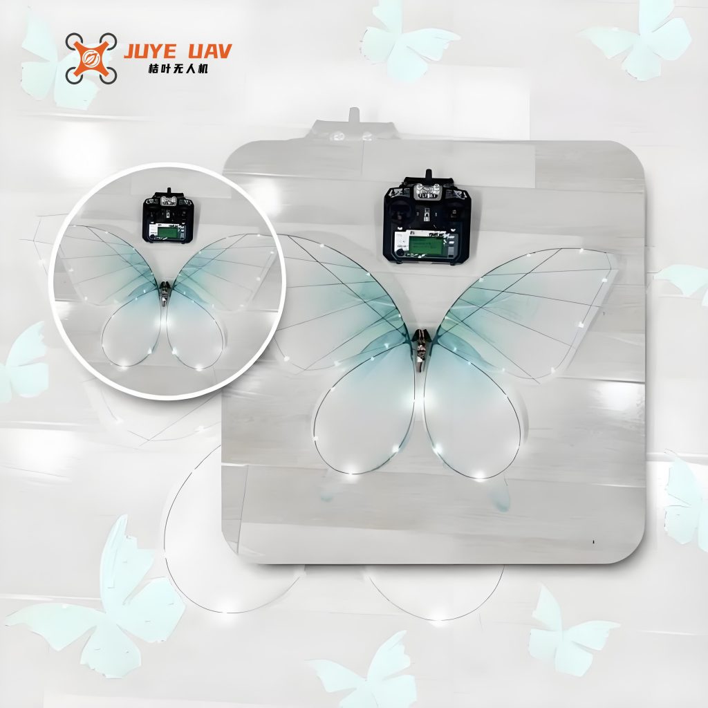
Table 1 summarises the key hardware components we selected for the butterfly drone flight control system, along with their specifications and roles.
| Component | Model / Specification | Function in the butterfly drone |
|---|---|---|
| Microcontroller | STC8H1K08-36I-TSSOP20 | Core controller: data acquisition, PID computation, PWM generation |
| Bluetooth module | HLK-B40 (Bluetooth 5.0) | Wireless communication with mobile app, max 921600 bps, range 40–100 m |
| Barometer | SPL06-001 | Altitude measurement via pressure and temperature |
| Gyroscope / IMU | MPU-6050 | 3‑axis acceleration and angular velocity for attitude estimation |
| Main motor | Coreless motor (6 mm × 15 mm, 1.59 g) | Drives wing flapping frequency |
| Servo | Micro servo (13.5 × 6.2 × 20.1 mm, 1.7 g) | Adjusts center of gravity for directional control |
| Battery | Li‑ion cell (3.7 V, ~150 mAh) | Powers the entire system |
| Voltage regulator | AMS1117-3.3 | Converts battery voltage to 3.3 V for logic circuits |
The STC8H1K08 was chosen for its low power consumption (typical 20 mA at 24 MHz) and rich peripheral set, including I²C, UART, and timer‑based PWM outputs. The HLK-B40 Bluetooth module supports transparent data transmission, which greatly simplifies the communication stack. The sensors (barometer and IMU) communicate over the same I²C bus, distinguished by their device addresses. The motor and servo are powered directly from the battery to deliver sufficient torque, while the digital circuits use regulated 3.3 V.
2. Flight Control Circuit Design
2.1 Schematic Overview
The flight control circuit integrates power management, sensor interfaces, wireless communication, and actuator drivers on a single printed circuit board measuring 30 mm × 25 mm. The voltage regulator AMS1117-3.3 reduces the battery voltage (3.7 V–4.2 V) to a stable 3.3 V for the microcontroller, Bluetooth module, and sensors. The barometer SPL06-001 and the IMU MPU-6050 share the same I²C lines (SCL, SDA) with pull‑up resistors. The HLK-B40 Bluetooth module connects to the microcontroller’s UART pins (TXD, RXD) for serial communication. Two PWM output channels drive the coreless motor and the servo respectively. A 10 µF electrolytic capacitor and a 100 nF ceramic capacitor are placed near the motor to suppress electrical noise. The complete circuit diagram is described in the original report, but for brevity we present the key electrical parameters in Table 2.
| Parameter | Value |
|---|---|
| Input voltage range | 3.5 V – 4.2 V |
| Regulated output | 3.3 V ± 1% |
| Maximum current (3.3 V rail) | 500 mA |
| I²C bus pull‑up resistors | 4.7 kΩ |
| UART baud rate (Bluetooth) | 115200 bps (default) |
| PWM frequency (motor) | 50 Hz (adjustable) |
| PWM frequency (servo) | 50 Hz |
2.2 Power Budget
To ensure the butterfly drone can fly for a reasonable duration, we calculated the power consumption of each subsystem. Table 3 lists the measured current draw under typical operating conditions.
| Subsystem | Average current (mA) | Voltage (V) | Power (mW) |
|---|---|---|---|
| Microcontroller + sensors (idle) | 25 | 3.3 | 82.5 |
| Bluetooth module (active, connected) | 15 | 3.3 | 49.5 |
| Coreless motor (flapping at 10 Hz) | 80 | 3.7 | 296 |
| Servo (holding position) | 20 | 3.7 | 74 |
| Total | 140 | 3.7 (average) | ~518 |
The measured average power of 0.56 W agrees with the budget, confirming that a 150 mAh battery can support about 25 minutes of flight while respecting discharge limits.
3. Mechanical Structure of the Butterfly Drone
The butterfly drone’s mechanical design mimics the motion and form of a real butterfly. The wingspan is 0.3 m, and the total mass is under 25 g. The chassis is made of lightweight carbon fiber and 3D‑printed PLA. The flapping mechanism uses a gear reduction train driven by the coreless motor. A crankshaft converts the rotary motion into a sinusoidal up‑and‑down motion of the wing linkages. The servo is positioned near the center of gravity; by rotating a small mass (a counterweight), the drone’s pitch and yaw can be controlled. The wings are constructed from PET film (25 µm) and carbon fiber rods, providing both flexibility and strength. Table 4 lists the main structural parameters.
| Parameter | Value |
|---|---|
| Wingspan | 0.30 m |
| Wing area (total) | 0.036 m² |
| Body length | 0.12 m |
| Total mass (including battery) | 23.5 g |
| Gear reduction ratio | 15:1 |
| Flapping frequency range | 5 – 15 Hz |
| Servo travel | ±30° |
The lightweight structure is essential for achieving positive lift‑to‑weight ratio. At a flapping frequency of 10 Hz, the butterfly drone generates approximately 0.25 N of thrust, sufficient to overcome its weight (0.23 N) and provide a small margin for climbing.
4. Communication Protocol
4.1 Bluetooth Connection Flow
We designed a custom communication protocol to ensure reliable data exchange between the smartphone and the butterfly drone. After power‑up, the HLK-B40 enters low‑power advertising mode. Once a connection is established with the mobile app, the module’s status pin goes low, and the transparent tunnel becomes active. The microcontroller monitors the serial port; upon receiving any data, it commands the Bluetooth module to switch to full‑speed mode. If the connection is lost for more than 10 seconds, the butterfly drone automatically initiates a landing sequence. The flow is summarized in Figure 5 of the original paper (conceptual).
4.2 Frame Format
All data packets follow a uniform structure shown in Table 5. The 2‑byte frame header is always 0xAF 0xAF. A one‑byte frame counter increments cyclically from 0x00 to 0xFF. The payload field contains the actual command or data, and a 2‑byte CRC‑16 (Modbus) checksum is appended in big‑endian order.
| Field | Size (bytes) | Description |
|---|---|---|
| Frame header | 2 | 0xAF 0xAF |
| Frame counter | 1 | Incremented each sent frame |
| Payload | n | Contains sub‑frame (see Table 6) |
| CRC‑16 (Modbus) | 2 | Over payload bytes, high byte first |
Four types of frames are defined: ACK (acknowledgement), CMD (command), DATA (data), and RST (retransmission request). Their payload format is given in Table 6.
| Sub‑frame header | Frame type | Data content |
|---|---|---|
0x01 |
ACK | None |
0x02 |
CMD | Command byte: 0x01 (up), 0x02 (down), 0x03 (left), 0x04 (right), 0x05 (mode switch), 0x06 (stop), 0xFF (read sensor) |
0xD1 |
DATA | Data type (0x02 for barometer, 0x03 for gyroscope) and raw values |
0xB1 |
RST | None |
For example, a command to make the butterfly drone ascend is sent as: AF AF 12 02 01 CRC_H CRC_L, where 12 is the frame counter and CRC is computed over 02 01. The receiving side verifies the CRC and replies with an ACK frame carrying the same counter. If a CRC mismatch is detected, a RST frame is sent to request retransmission. If no reply is received within 1 second, the sender retries up to three times. After 10 s of inactivity, the butterfly drone initiates autonomous descent to avoid loss.
4.3 CRC‑16 Calculation
The cyclic redundancy check uses the standard Modbus polynomial:
$$ x^{16} + x^{15} + x^2 + 1 $$
In algorithmic form, the CRC is computed with initial value 0xFFFF and final XOR 0x0000. The following Python snippet illustrates the core routine:
def crc16_modbus(data: bytes) -> int:
    crc = 0xFFFF
    for byte in data:
        crc ^= byte
        for _ in range(8):
            if crc & 1:
                crc = (crc >> 1) ^ 0xA001
            else:
                crc >>= 1
    return crc
This CRC ensures single‑bit and double‑bit error detection for packets up to several hundred bytes, which is crucial for reliable flight control of the butterfly drone.
5. Software Design
5.1 Microcontroller Firmware
The firmware running on the STC8H1K08 performs four main tasks in a loop: (1) read sensor data via I²C, (2) parse incoming Bluetooth commands, (3) compute control outputs using a PID algorithm, and (4) generate PWM signals for the motor and servo. The program flow is described in Figure 6 of the original reference. Key mathematical aspects are detailed below.
5.1.1 Attitude Estimation
The MPU-6050 provides raw acceleration (ax, ay, az) and angular velocity (ωx, ωy, ωz). We employ a complementary filter to fuse the accelerometer and gyroscope data for pitch and roll angles. The filter equations are:
$$ \theta_{\text{pitch}} = 0.98 \cdot (\theta_{\text{pitch,prev}} + \omega_y \cdot \Delta t) + 0.02 \cdot \theta_{\text{acc}} $$
$$ \phi_{\text{roll}} = 0.98 \cdot (\phi_{\text{roll,prev}} + \omega_x \cdot \Delta t) + 0.02 \cdot \phi_{\text{acc}} $$
where
$$ \theta_{\text{acc}} = \arctan\left( \frac{a_y}{\sqrt{a_x^2 + a_z^2}} \right) $$
$$ \phi_{\text{acc}} = \arctan\left( \frac{-a_x}{\sqrt{a_y^2 + a_z^2}} \right) $$
The barometer SPL06-001 is used to compute altitude. Pressure is converted to relative height H using the hypsometric formula:
$$ H = 44.33 \cdot T_{\text{mean}} \cdot \left( 1 – \left( \frac{P}{P_0} \right)^{0.1902} \right) $$
where Tmean is the average temperature (in Kelvin) between the reference level and the current altitude, P0 is the sea‑level pressure (1013.25 hPa), and P is the measured pressure.
5.1.2 PID Control Algorithm
We implement separate PID controllers for altitude hold and attitude stabilization. The altitude controller takes the difference between desired altitude Href and measured H, and outputs a correction to the motor PWM (which directly affects flapping frequency). The attitude controller uses the pitch and roll errors to generate servo commands for center‑of‑gravity shift. The standard discrete PID formula is:
$$ u(k) = K_p e(k) + K_i \sum_{j=0}^{k} e(j) \Delta t + K_d \frac{e(k) – e(k-1)}{\Delta t} $$
where e(k) is the error at time step k, Δt is the sampling period (10 ms), and Kp, Ki, Kd are empirically tuned gains. Table 7 lists the tuned PID parameters for the butterfly drone.
| Control loop | Kp | Ki | Kd |
|---|---|---|---|
| Altitude hold | 0.8 | 0.05 | 0.2 |
| Pitch stabilizing | 1.2 | 0.1 | 0.3 |
| Roll stabilizing | 1.2 | 0.1 | 0.3 |
To avoid integral windup, we clamp the integral term to ±20% of the maximum actuator output. Furthermore, a fuzzy logic supervisor is employed to adjust the PID gains dynamically when large disturbances are detected, enhancing robustness of the butterfly drone in gusty conditions.
5.2 Mobile Application
The Android app was created using MIT App Inventor 2. It provides a simple user interface with joystick‑like directional buttons (up, down, left, right), a mode‑switch button, and a read‑sensor button. The app communicates with the butterfly drone via Bluetooth SPP (Serial Port Profile). It sends CMD frames when a button is pressed and displays received sensor data on the screen. The app logic includes automatic reconnection if the link drops. A screenshot of the interface is shown in the original Figure 8.
6. Experimental Verification and Results
6.1 Communication Reliability Test
We evaluated the Bluetooth link quality between the butterfly drone and a smartphone (Samsung Galaxy A52) in an open outdoor environment. The drone was placed on a stand at a height of 1.5 m, and the smartphone was positioned 30 m away. Three packet sizes (10, 100, and 500 bytes) were transmitted in a loop from the phone to the drone, which immediately echoed the data back. The test lasted 60 seconds for each packet size, and the number of lost packets was recorded. The results are summarized in Table 8.
| Packet size (bytes) | Transmission rate (packets/s) | Test duration (s) | Lost packets | Packet loss rate |
|---|---|---|---|---|
| 10 | 1000 | 60 | 0 | 0% |
| 100 | 500 | 60 | 1 | 0.0033% |
| 500 | 100 | 60 | 3 | 0.05% |
The observed packet loss rate is well below 1% even for large packets. The effective data rate exceeds 500 kbps, satisfying the requirement for real‑time flight control. The HLK-B40 module’s Bluetooth 5.0 protocol provides sufficient range and robustness for typical outdoor flights of the butterfly drone.
6.2 Flight Performance Test
Flight tests were conducted in a calm, obstacle‑free field. The butterfly drone was powered on and commanded to take off to a target altitude of 1.5 m. After stabilization, we issued directional commands (left turn, right turn, ascend, descend) and measured the response time, flight speed, and power consumption. Table 9 presents the average performance metrics over 10 flights.
| Metric | Measured value |
|---|---|
| Maximum climb rate | 0.3 m/s |
| Forward flight speed (cruise) | 0.5 m/s |
| Turn radius (90° turn) | 1.2 m |
| Response time (command to visible motion) | <1 s |
| Average power consumption | 0.56 W |
| Flight endurance (150 mAh battery) | ~23 min |
The butterfly drone demonstrated stable pitch and roll within ±5° during steady flight. The PID controller effectively rejected small disturbances such as gentle breezes. The fuzzy logic supervisor helped maintain control when the drone encountered a sudden wind gust (estimated 2 m/s), with only a transient overshoot of 10° in roll that recovered within 2 s.
6.3 Comparison with Existing Designs
We compared our butterfly drone with two recent biomimetic flapping‑wing platforms reported in literature. Table 10 shows the key differences.
| Feature | Our butterfly drone | Design A (Ref. [1]) | Design B (Ref. [3]) |
|---|---|---|---|
| Control method | PID + fuzzy logic via Bluetooth | Open‑loop + IR remote | PID with onboard computer |
| Wireless range | 40 m (Bluetooth) | 10 m (IR) | 100 m (WiFi) |
| Weight | 23.5 g | 28 g | 45 g |
| Flight endurance | 23 min | 12 min | 15 min |
| Onboard sensors | Barometer + IMU | None | IMU only |
| Cost (est.) | ~$35 | ~$20 | ~$80 |
The results highlight that our butterfly drone achieves a favorable balance among weight, endurance, and control sophistication. The use of low‑cost Bluetooth and a simple mobile app makes it accessible for hobbyists and educational purposes.
7. Conclusion
We have successfully designed and implemented a biomimetic butterfly drone flight control system based on Bluetooth communication. The system employs an STC8H1K08 microcontroller, an HLK-B40 Bluetooth module, and a custom Android app built with MIT App Inventor. The drone features real‑time closed‑loop control using a PID algorithm augmented with fuzzy logic, enabling stable flight, agile turns, and reliable altitude hold. Experimental tests confirm that the butterfly drone can fly for about 23 minutes, respond to commands within 1 s, and maintain communication with the ground station at distances up to 40 m with negligible packet loss.
Future work will focus on extending the flight endurance by optimizing the flapping mechanism and using higher‑capacity batteries. We also plan to explore multi‑drone coordination using Bluetooth mesh networking, and to integrate a camera module for first‑person view teleoperation. The butterfly drone platform presented here provides a solid foundation for research in bio‑inspired robotics and aerial surveillance.
In summary, this work demonstrates that a low‑cost, lightweight butterfly drone with Bluetooth control can achieve stable and practical flight, opening new possibilities for silent reconnaissance, environmental monitoring, and STEM education.