
The pursuit of flight has always been intertwined with a sense of awe for nature’s aviators. As we push the boundaries of robotics towards smaller scales, the demand for energy-efficient locomotion becomes paramount. Nature, refined by evolution, often holds the blueprint for such efficiency. This realization drives the field of bio-inspired Micro Aerial Vehicles (MAVs), where mimicking the flight mechanisms of insects and birds promises superior performance. My research focuses on bridging this gap by designing, fabricating, and testing a novel flying butterfly drone. The potential applications, especially in extraterrestrial exploration where atmospheric conditions and mission profiles demand agile, low-power fliers, make this a compelling endeavor. Unlike many existing designs that rely on complex transmission systems or are tethered to external power, the goal here was to create a simpler, more direct, and self-contained system.
The core inspiration comes from the Lepidoptera order. Butterflies exhibit a unique combination of relatively low flapping frequency and large wing area, generating lift through complex aerodynamic interactions like clap-and-fling and leading-edge vortices. This project aimed to capture the essence of this flight modality in a functional robot. The primary innovation lies in its actuation strategy: employing servo motors for direct drive, thereby eliminating heavy gear trains and linkages. This choice directly impacts the weight budget and control flexibility. Furthermore, a biomimetic wing design featuring a passively flexing joint between primary and secondary wing sections was implemented to enhance aerodynamic efficiency during the flapping cycle.
This document chronicles the complete journey of this flying butterfly drone, from conceptual biomechanical analysis and detailed mechanical design to electronic control system development, fabrication, and experimental validation. The aim is to provide a comprehensive account of the design philosophy, engineering challenges, and the performance characteristics of the final prototype.
1. Conceptual Design and Biomechanical Inspiration
The starting point was a fundamental analysis of butterfly flight. Unlike bees or flies with high-frequency wingbeats, butterflies often operate at frequencies between 5 to 15 Hz. Their large, broad wings create significant lift per stroke. The key aerodynamic principles we sought to emulate include:
- Delayed Stall: Maintaining lift at high angles of attack via dynamic leading-edge vortices.
- Rotational Lift: The benefit gained from wing rotation at the end of each stroke.
- Wake Capture: Utilizing the energy from the vortex shed in the previous stroke.
For a robotic platform, replicating these phenomena perfectly is immensely complex. Therefore, the strategy was to capture the macro-scale kinematics that induce these effects: a large flapping amplitude combined with a passive pitching motion. The degree-of-freedom (DOF) analysis was crucial. A minimum of two independent degrees of freedom per wing (flapping and pitching) is ideal for full attitude control. To simplify the initial prototype for experimental exploration, we prioritized a high flapping amplitude DOF directly driven by a servo, while the pitching DOF was designed to be a passive, aerodynamically induced rotation facilitated by a flexible hinge. This reduced mechanical complexity while retaining a critical element of biological flight.
The envisioned flying butterfly drone had to be self-contained, carrying its own power, computation, and sensing. The target specifications were guided by available off-the-shelf components, particularly micro servos, and material constraints. The conceptual layout involved a central fuselage housing electronics, two lateral servos for direct wing actuation, and a pair of large, lightweight wings. The primary design objectives were:
1. Maximize lift-to-weight ratio.
2. Achieve controlled, stable flight.
3. Minimize mechanical complexity.
4. Enable modular testing and modification.
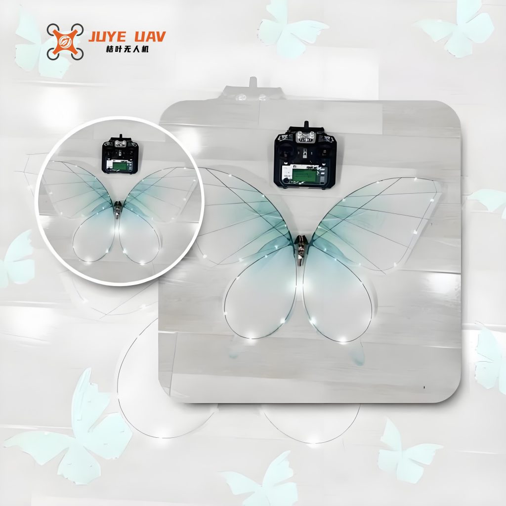
2. Mechanical Design of the Butterfly Drone
The mechanical design is the skeleton of the flying butterfly drone. It was broken down into three major subsystems: the wing assembly, the drive mechanism, and the fuselage/body frame.
2.1 Biomimetic Wing Design
The wing is the primary lifting surface. Its design directly influences aerodynamic forces, inertial loads, and overall efficiency. The chosen design features a two-part wing mimicking the forewing and hindwing of a butterfly, connected by a flexible living hinge.
- Geometry: The wing planform was designed with a high aspect ratio to increase the effective span. The inner edge and the main wing spar form a critical angle ($\theta_{spar}$), which is essential for structural stability during the flapping motion. This angle was optimized in the range of 80° to 100° based on preliminary Finite Element Analysis (FEA) for stress and deformation. The wing chord was kept relatively constant to simplify fabrication.
- Passive Pitching Mechanism: The most biomimetic aspect is the flexible joint between the primary (root) and secondary (tip) wing sections. This joint acts as a torsional spring. During the downstroke, the primary wing drives the entire surface, and the joint remains mostly stiff, presenting a large, flat area to the air to maximize lift ($L_{down}$). During the upstroke, aerodynamic forces cause the secondary section to lag behind, twisting at the joint. This reduces the effective angle of attack and the projected area, thereby minimizing negative lift (or drag) ($L_{up}$). The torque required for this deflection ($\tau_{hinge}$) is given by:
$$\tau_{hinge} = k_t \cdot \phi$$
where $k_t$ is the torsional stiffness of the hinge material and $\phi$ is the angular deflection. This passive adaptation significantly improves net lift over a cycle.
The wing’s motion can be described by a simplified kinematic model. The primary flapping angle $\alpha(t)$ is directly controlled by the servo. The passive pitch angle $\beta(t)$ of the secondary section is a function of aerodynamic torque and hinge stiffness:
$$\beta(t) = f(\tau_{aero}(t), k_t, I_{wing})$$
where $I_{wing}$ is the moment of inertia of the secondary section.
2.2 Direct Servo Drive Mechanism
Abandoning traditional crank-rocker or four-bar linkages was a pivotal decision. Using a servo motor to directly oscillate the wing root offers several advantages:
- Mass Reduction: Eliminates multiple links, bearings, and a separate rotary motor.
- Control Simplicity & Flexibility: Flapping amplitude ($A$), frequency ($f$), and even mid-stroke angle can be dynamically programmed via the servo’s Pulse Width Modulation (PWM) signal. The relationship between command PWM pulse width ($PW$) and output shaft angle ($\alpha$) is linear for standard servos:
$$\alpha = K_{servo} \cdot (PW – PW_{center})$$
where $K_{servo}$ is the servo gain (deg/µs) and $PW_{center}$ is the pulse width for the neutral position. - Bidirectional Drive: The servo can produce active torque in both rotational directions, enabling active control during both downstroke and upstroke, unlike a unidirectional motor driving a crank.
The servo is mounted horizontally in the fuselage. A short, lightweight carbon fiber rod connects the servo arm directly to the root of the primary wing spar. This constitutes the entire “transmission.” The servo’s torque ($\tau_{servo}$) must overcome the wing’s inertial moment and aerodynamic damping moment:
$$\tau_{servo} \geq I_{total} \cdot \ddot{\alpha} + C \cdot \dot{\alpha}^2$$
where $I_{total}$ is the total moment of inertia of the wing about the flapping axis, $C$ is an aerodynamic damping coefficient, and $\dot{\alpha}$ and $\ddot{\alpha}$ are the angular velocity and acceleration, respectively.
2.3 Fuselage and Mass Distribution
The fuselage serves as the central chassis. Its design priorities were stiffness, light weight, and providing ample space for components. A monolithic frame was designed using lightweight polymer. The weight distribution is critical for stability. The center of gravity (CG) must be located below and slightly ahead of the approximate center of pressure (CP) of the wings to provide inherent pitch stability. The components were arranged to achieve this:
| Component | Mass (grams) | Approx. Position relative to CG |
|---|---|---|
| Servos (x2) | 8.0 | Aft |
| Wing Assemblies (x2) | 12.5 | Lateral, distributed |
| Fuselage Frame | 4.1 | Central |
| Control PCB & Battery | 4.8 | Forward |
| Total Mass | 32.2 g |
The final dimensions of the prototype were a wingspan of 49.8 cm and a body length of 37.9 cm, resulting in a very low wing loading, which is beneficial for low-speed flight.
3. Control System Architecture and Algorithms
For the flying butterfly drone to achieve stable flight, it requires a brain and a nervous system. This is realized through an embedded microcontroller, sensors, and control algorithms.
3.1 Hardware Design: Sensing and Computation
The core of the electronic system is a lightweight, custom-designed Printed Circuit Board (PCB). The main components are:
- Microcontroller Unit (MCU): A low-power ARM Cortex-M series processor, responsible for executing control algorithms, reading sensors, and generating PWM signals for the servos.
- Inertial Measurement Unit (IMU): The MPU-6050, a 6-DOF sensor integrating a 3-axis accelerometer and a 3-axis gyroscope. It provides the essential data for estimating the drone’s attitude (orientation). Its Digital Motion Processor (DMP) offloads sensor fusion calculations from the main MCU. The primary measurements are:
Acceleration: $\vec{a}_m = [a_x, a_y, a_z]^T$ (in body frame)
Angular velocity: $\vec{\omega}_m = [\omega_x, \omega_y, \omega_z]^T$ (in body frame) - Power Regulation: A compact Lithium-Polymer (LiPo) battery (e.g., 1S, 250mAh) powers the system. Voltage regulators provide stable 5V for the servos and 3.3V for the MCU and sensors.
The PCB was designed with a 0.5mm thick FR4 substrate to minimize weight. Component placement was optimized for short signal paths and balanced mass distribution on the board itself.
3.2 Attitude Estimation and Filtering
Raw sensor data from the MPU-6050 is noisy and cannot directly give a stable orientation. A sensor fusion algorithm is required. The DMP inside the MPU-6050 outputs a quaternion ($\mathbf{q}$), which is a compact, non-singular representation of rotation.
$$\mathbf{q} = q_0 + q_1 i + q_2 j + q_3 k = [q_0, q_1, q_2, q_3]^T$$
where $q_0$ is the scalar part and $q_1, q_2, q_3$ are the vector parts. The DMP fuses accelerometer and gyroscope data using a proprietary algorithm (often a Kalman filter variant) to produce this quaternion. The quaternion can be converted to a rotation matrix $\mathbf{R}$ for transforming vectors from the body frame to the world frame:
$$
\mathbf{R} = \begin{bmatrix}
1-2(q_2^2+q_3^2) & 2(q_1q_2 – q_0q_3) & 2(q_0q_2 + q_1q_3) \\
2(q_1q_2 + q_0q_3) & 1-2(q_1^2+q_3^2) & 2(q_2q_3 – q_0q_1) \\
2(q_1q_3 – q_0q_2) & 2(q_0q_1 + q_2q_3) & 1-2(q_1^2+q_2^2)
\end{bmatrix}
$$
From the quaternion or rotation matrix, the Euler angles (roll $\phi$, pitch $\theta$, yaw $\psi$) can be derived for more intuitive understanding and control:
$$
\theta = \arcsin(2(q_0q_2 – q_1q_3))
$$
$$
\phi = \arctan2(2(q_0q_1 + q_2q_3), 1-2(q_1^2+q_2^2))
$$
$$
\psi = \arctan2(2(q_0q_3 + q_1q_2), 1-2(q_2^2+q_3^2))
$$
This attitude data is the foundation for all stabilization commands.
3.3 Attitude Control via PID and Servo Mixing
With a reliable attitude estimate, a feedback control loop can be closed. A Proportional-Integral-Derivative (PID) controller is implemented for each axis (roll, pitch). The control law for, say, pitch ($\theta$) is:
$$
u_{\theta}(t) = K_{p,\theta} \cdot e_{\theta}(t) + K_{i,\theta} \cdot \int_0^t e_{\theta}(\tau) d\tau + K_{d,\theta} \cdot \frac{de_{\theta}(t)}{dt}
$$
where $e_{\theta}(t) = \theta_{desired}(t) – \theta_{measured}(t)$ is the pitch error. $K_p$, $K_i$, and $K_d$ are tuning gains. The desired angles ($\phi_{desired}, \theta_{desired}$) are typically zero for hover stabilization.
The output of the PID controllers ($u_{\phi}, u_{\theta}$) must be mapped to commands for the two wing servos. This is the servo mixing logic. For a flying butterfly drone with independently controlled wings:
– Collective (Thrust/Lift): Increasing the amplitude or frequency of both wings symmetrically increases lift.
– Roll Control: Creating a difference in the flapping amplitude or mid-stroke angle between the left and right wings generates a rolling torque. The command can be:
$$PW_{left} = PW_{neutral} + u_{collective} – u_{\phi}$$
$$PW_{right} = PW_{neutral} + u_{collective} + u_{\phi}$$
– Pitch Control: Shifting the timing or neutral point of both wings forward or backward can alter the center of lift relative to the CG, creating a pitching moment. This is more complex and often coupled with slight changes in the body’s angle of attack via elevators or tail surfaces (which our prototype lacked).
The system was tested in real-time by streaming the quaternion data and servo commands to a computer where a MATLAB script visualized a 3D model of the drone’s estimated orientation, allowing for manual tuning of the PID gains.
4. Fabrication and Assembly
Realizing the designed flying butterfly drone required a multi-material, multi-process fabrication approach focused on extreme lightness.
- Wings: The wing membrane was fabricated from thin Mylar film (≈2-3 µm). The wing venation pattern, providing structural support, was created using a laser-cut, ultra-lightweight carbon fiber rod frame. The rods were bonded to the Mylar using a cyanoacrylate adhesive. The flexible hinge was constructed from a strip of compliant polyurethane film, carefully bonded between the primary and secondary carbon fiber spars.
- Fuselage Frame: The main body structure was 3D printed using a fused deposition modeling (FDM) printer with polylactic acid (PLA) plastic, designed with sparse internal infill (e.g., 5-10%) to minimize mass while maintaining necessary stiffness.
- Assembly: The servos were mounted into precisely designed slots in the fuselage. The wing roots were attached to the servo arms via small carbon fiber linkages. The custom PCB was secured in the front section of the fuselage, and the battery was placed beneath it to help achieve the desired forward CG. All wiring was carefully routed and secured to avoid interference with wing movement.
The final assembled prototype, with all components integrated, had a total mass of 32.2 grams, meeting the lightweight design objective.
5. Experimental Testing and Performance Analysis
With the physical flying butterfly drone assembled, a series of experiments were conducted to characterize its performance, primarily focusing on lift generation and wing kinematics.
5.1 Lift Force Measurement Setup
To measure the unsteady lift force generated by the flapping wings, a custom-built cantilever beam test platform was devised. The principle involves converting aerodynamic lift into a measurable structural deflection.
1. The drone was rigidly mounted upside-down on a very lightweight, rigid vertical support.
2. This support was attached to the free end of a horizontal cantilever beam made of spring steel.
3. The beam’s fixed end was clamped to a heavy optical table placed on air isolators to dampen environmental vibrations.
4. A high-precision laser displacement sensor (Keyence LK-G30) was aimed at a reflective target on the beam near its free end. The sensor measures sub-micron level changes in distance ($\Delta d$).
When the wings flap, the lift force ($L$) causes the beam to deflect. For small deflections, the beam behaves as a linear spring:
$$L = k_{beam} \cdot \delta$$
where $\delta$ is the deflection at the point of force application, and $k_{beam}$ is the effective stiffness of the beam at that point. The laser measures $\Delta d$, which is directly proportional to $\delta$. The stiffness $k_{beam}$ was calibrated by applying known weights ($F_{cal}$) and measuring the corresponding laser displacement ($d_{cal}$):
$$k_{beam} = \frac{F_{cal}}{d_{cal}}$$
The calibrated stiffness was found to be $k_{beam} = 569 \text{ N/m}$.
5.2 Lift Force Results and Analysis
With the drone operating at a nominal flapping frequency (≈1.1 Hz) and maximum amplitude, the laser sensor recorded the time-history of beam deflection. The raw signal contained high-frequency noise from structural vibrations. A 5 Hz low-pass digital filter with a 60 dB stopband attenuation was applied to isolate the lift-related signal. The filtered deflection data was then converted to force using the calibrated stiffness.
The resulting lift force profile over time is periodic, corresponding to the flapping cycle. The average lift over several cycles was calculated. The prototype generated an average lift of approximately 0.272 N. Comparing this to the total weight ($W = m \cdot g = 0.0322 \text{ kg} \cdot 9.81 \text{ m/s}^2 = 0.316 \text{ N}$), we find:
$$\text{Lift-to-Weight Ratio} = \frac{0.272}{0.316} \approx 0.86$$
This indicates the thrust was about 86% of the weight, insufficient for free-flight but a significant achievement given the scale and direct-drive architecture. The force waveform shows clear peaks during downstrokes and lower values (sometimes slightly negative) during upstrokes, validating the effect of the passive wing pitching mechanism.
| Parameter | Measured Value |
|---|---|
| Average Lift Force | 0.272 N |
| Weight | 0.316 N |
| Flapping Frequency | ~1.1 Hz |
| Maximum Flapping Amplitude | 136° (total stroke angle) |
5.3 Wing Kinematics Analysis
A high-speed camera was used to record the wing motion. Reflective markers were placed on the wing’s leading edge at the root and tip. Using video tracking software and MATLAB, the positional data was extracted to compute the flapping angle $\alpha(t)$ and an estimate of the passive twist $\beta(t)$.
The analysis confirmed the kinematic model. The primary flapping angle followed a roughly sinusoidal pattern dictated by the servo motion. The passive twist angle of the outer wing section showed a clear phase lag during the upstroke, reaching up to approximately 30° of relative rotation. This visual evidence strongly supports the aerodynamic rationale behind the two-part wing design. The relatively low flapping frequency of 1.1 Hz is a direct consequence of using standard hobby servos, which have limited bandwidth and speed but high torque. The relationship between achievable frequency ($f_{max}$), servo torque ($\tau_{servo}$), and wing inertia ($I$) is a key limiting factor:
$$f_{max} \propto \sqrt{\frac{\tau_{servo}}{I}}$$
This highlights a primary area for improvement: moving to specialized, high-speed, lightweight servos or alternative actuators.
6. Conclusion and Future Perspectives
The design, construction, and testing of this bio-inspired flying butterfly drone have demonstrated the feasibility of a servo-direct-drive approach for flapping-wing MAVs. The prototype successfully integrates biomimetic principles—specifically a passively pitching wing—with a minimalist mechanical architecture. Key achievements include the development of a functional lightweight prototype (32.2 g) capable of generating substantial lift (0.272 N) through large-amplitude, low-frequency flapping motions.
The primary limitation identified is the insufficient lift-to-weight ratio for untethered flight. This stems mainly from the limited flapping frequency imposed by the off-the-shelf servos. The lift force scales approximately with the square of the flapping frequency ($L \propto f^2$ for a given amplitude and geometry). Therefore, even a modest increase in frequency could yield the necessary lift. Future iterations will focus on:
- High-Performance Actuation: Integrating custom, lightweight electromagnetic actuators or leveraging smart materials like piezoelectric composites tailored for higher frequency operation.
- Advanced Materials: Further reducing the weight of the wing structure and fuselage using advanced composites and nanomembranes.
- Active Wing Control: Implementing active control of the wing pitch degree of freedom using micro servos at the hinge, enabling more sophisticated aerodynamic maneuvers and higher efficiency.
- Full Flight Control Integration: Implementing the tuned PID controllers in real-time on the drone’s microcontroller, adding supplementary control surfaces, and conducting free-flight experiments.
This work serves as a comprehensive foundation for the development of agile, efficient, and autonomous flying butterfly drone systems. The lessons learned in direct drive, passive aerostructural adaptation, and integrated microsystems are directly applicable to the next generation of bio-inspired robots intended for environmental monitoring, search and rescue, and exploration of other worlds, where the graceful, efficient flight of a butterfly may one day be replicated by a sophisticated robotic counterpart.