
The operational effectiveness of UAV drones, particularly quadrotors, in critical applications such as power line inspection, is often compromised by actuator saturation. During demanding maneuvers—such as abrupt roll during emergency obstacle avoidance, sustained maximum thrust for hovering against strong winds, load swing during equipment deployment or clearing, and reduced motor performance under low-battery conditions—the control inputs can easily exceed the physical limits of the motors. Traditional anti-windup or saturation compensation methods frequently operate at the force or torque level, decoupling the compensation from the actual, nonlinear dynamics between motor speed and thrust. This paper introduces an integrated control strategy that directly addresses physical rotor speed constraints through a novel anti-saturation mechanism, coupled with online dynamic trajectory generation for autonomous navigation. Unlike conventional approaches, the proposed method establishes a saturation compensation paradigm at the rotor speed level. It incorporates a feedforward compensation mechanism to align the controller’s dynamic demands with the physically realizable actuator response, thereby enhancing tracking performance and stability under strict input constraints. The core of this approach for UAV drones requires only a measurable “thrust-to-speed” model, making it widely applicable across various multi-rotor platforms.
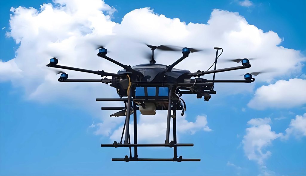
The inspection system for UAV drones employs a hierarchical architecture integrating perception, decision-making, and execution. The perception layer utilizes a Intel RealSense D435i depth camera and an Inertial Measurement Unit (IMU) for real-time three-dimensional reconstruction of the inspection target, such as power lines. Target detection is performed using an enhanced YOLOv8 algorithm. The decision-making layer, hosted on a Jetson TX2 NX embedded computing unit, runs the proposed anti-saturation control algorithm, incorporating dynamic auxiliary systems and disturbance observers. The execution layer translates high-level commands into motor speed signals via a Brushless DC (BLDC) motor dynamic model, ensuring precise thrust allocation within physical limits. Data transmission and multi-UAV drone coordination are facilitated by a 5G module. The process for obtaining the desired position, crucial for the controller, involves capturing multi-modal data streams, aligning depth and color images, performing target detection and bounding box extraction via YOLOv8, and finally calculating the three-dimensional coordinates in the camera frame through inverse perspective transformation. These coordinates are then transformed into the desired position $P_d = (x_d, y_d, z_d)$ in the world frame for the controller.
The dynamic model of a quadrotor UAV drone is established under standard assumptions (rigid body, symmetrical structure, negligible aerodynamic effects except drag). Two coordinate frames are defined: the earth-fixed inertial frame $\{O_e X_e Y_e Z_e\}$ and the body-fixed frame $\{O_b X_b Y_b Z_b\}$. Let $P = [x, y, z]^T$ and $\eta = [\phi, \theta, \psi]^T$ denote the position and orientation (roll, pitch, yaw) in the inertial frame, respectively. The rotation matrix from body to inertial frame is $R \in SO(3)$. The translational and rotational dynamics are given by:
$$ m\ddot{P} = R F_B – mg e_3 – D_t \dot{P} + d_t $$
$$ J \dot{\omega} = \tau_B – \omega \times J \omega – D_r \omega + d_r $$
where $m$ is the mass, $g$ is gravity, $e_3 = [0,0,1]^T$, $J$ is the inertia matrix, $\omega$ is the angular velocity in the body frame, $D_t$ and $D_r$ are diagonal drag coefficient matrices, and $d_t$, $d_r$ represent external disturbances. The control inputs from the four rotors are related to the total thrust $T$ and body torques $\tau_B = [\tau_\phi, \tau_\theta, \tau_\psi]^T$ through the allocation matrix:
$$
\begin{bmatrix}
T \\
\tau_\phi \\
\tau_\theta \\
\tau_\psi
\end{bmatrix}
=
\begin{bmatrix}
b & b & b & b \\
0 & -lb & 0 & lb \\
-lb & 0 & lb & 0 \\
d & -d & d & -d
\end{bmatrix}
\begin{bmatrix}
\Omega_1^2 \\
\Omega_2^2 \\
\Omega_3^2 \\
\Omega_4^2
\end{bmatrix}
= M \boldsymbol{\Omega}^2
$$
Here, $b$ and $d$ are the thrust and drag coefficients, $l$ is the arm length, and $\Omega_i$ is the rotational speed of the $i$-th motor. The primary constraint is the physical limit on motor speed: $0 < \Omega_i < \Omega_{max}$. The core problem is to design a control law for $\boldsymbol{\Omega}$ that ensures accurate tracking of a desired trajectory $P_d(t), \psi_d(t)$ while strictly respecting $\Omega_i \in (0, \Omega_{max})$, despite model uncertainties and disturbances common in UAV drone operations.
The proposed solution is a dual-loop backstepping control structure with an integrated anti-saturation mechanism. The outer loop controls position $(x, y, z)$ and the inner loop controls attitude $(\phi, \theta, \psi)$. The key innovation lies in the anti-saturation compensation applied directly to the rotor speed commands.
For the attitude and height inner loop, define the state vectors $x_A = [z, \phi, \theta, \psi]^T$ and $x_B = [\dot{z}, \dot{\phi}, \dot{\theta}, \dot{\psi}]^T$. The dynamic equation can be written as $\dot{x}_B = f_A(x_A, x_B) + B_A \boldsymbol{\Omega} + d_A$. Let the desired state be $x_{Ad}$. The tracking error is $E_A = x_A – x_{Ad}$. A virtual control law $\alpha_A$ is designed via backstepping to stabilize $E_A$. Defining a new error $E_B = x_B – \alpha_A$, the final control law for the rotor speed squares is derived as:
$$ \boldsymbol{\Omega}^* = B_A^{\dagger} [ \dot{\alpha}_A – f_A – C_{1A}E_A – C_{2A}E_B – \hat{d}_A – \lambda_A ] $$
where $C_{1A}, C_{2A}$ are positive definite gain matrices, $\hat{d}_A$ is a disturbance estimate, and $\lambda_A$ is the anti-saturation compensation vector for the inner loop. The desired roll and pitch angles $(\phi_d, \theta_d)$ are not directly commanded but are derived from the outer-loop virtual controls $U_x$ and $U_y$:
$$ \phi_d = \arcsin(U_x \sin\psi_d – U_y \cos\psi_d) $$
$$ \theta_d = \arctan\left( \frac{U_x \cos\psi_d + U_y \sin\psi_d}{U_z} \right) $$
where $[U_x, U_y, U_z]^T$ is a virtual force vector in the inertial frame. The outer loop position control follows a similar backstepping procedure for states $x_a = [x, y]^T$ and $x_b = [\dot{x}, \dot{y}]^T$, yielding the virtual control law $U = [U_x, U_y]^T$.
The central anti-saturation mechanism is applied to the final motor speed commands $\Omega_i$ and the outer-loop virtual controls $U_j$ ($j=x,y$). For motor speeds, the saturated control input is $\Omega_{i,sat} = \text{sat}(\Omega_i^*) = \max(0, \min(\Omega_i^*, \Omega_{max}))$. To counteract the detrimental effects of this saturation, an auxiliary compensation system is designed. Let $\Delta \Omega_i = \Omega_{i,sat} – \Omega_i^*$. The dynamics for an auxiliary variable $\lambda_i$ are defined as:
$$
\dot{\lambda}_i =
\begin{cases}
-g_i(\Delta\Omega_i) \frac{\lambda_i}{|\lambda_i|} – k_i \lambda_i, & |\lambda_i| \ge \epsilon_i \\
0, & |\lambda_i| < \epsilon_i
\end{cases}
$$
with $g_i(\Delta\Omega_i) = \Delta\Omega_i^2 / 2 + b |\Delta\Omega_i|$, where $b$ is a positive constant, $k_i > 0$, and $\epsilon_i$ is a small positive threshold. The initial condition is $\lambda_i(0) = \Delta\Omega_i(0)/b$. This mechanism actively pulls the control signal back within limits when saturation occurs ($g_i$ term) and drives the compensation to zero once the signal is within bounds ($k_i$ term). The same structure is applied to compensate for saturation limits on $U_x$ and $U_y$, ensuring the derived attitude commands remain feasible. The stability of the entire closed-loop system for the UAV drone is proven using Lyapunov theory, showing that all tracking errors and auxiliary variables converge to a small neighborhood of zero.
The performance of the proposed controller for UAV drones is validated through simulation in a Gazebo/ROS environment modeling a power line inspection mission. The UAV drone parameters are listed in the table below.
| Parameter | Value | Unit |
|---|---|---|
| Mass ($m$) | 2.04 | kg |
| Arm Length ($l$) | 0.225 | m |
| $J_{xx}$ | 0.0211 | kg·m² |
| $J_{yy}$ | 0.0219 | kg·m² |
| $J_{zz}$ | 0.0366 | kg·m² |
| Thrust Coeff. ($b$) | 2.236e-5 | N/(rad/s)² |
| Drag Coeff. ($d$) | 4.350e-7 | Nm/(rad/s)² |
| Motor Time Constant | 0.05 | s |
| Max Rotor Speed ($\Omega_{max}$) | 9600 | r/min |
The inspection trajectory involves take-off, horizontal cruising, two 90-degree turns, and landing. The simulation results demonstrate the efficacy of the proposed method for UAV drones. The 3D trajectory tracking shows a very close match between the desired and actual paths. The position tracking errors in X, Y, and Z axes converge and remain within 0.05 m, 0.12 m, and 0.16 m, respectively. The attitude angles track their desired profiles with errors less than 0.05 rad, and the outer-loop virtual controls $U_x$, $U_y$ are maintained within the feasible range of $[-0.8535, 0.8535]$. Critically, the motor speed commands for all four rotors, as shown in the comparison table below, remain strictly within the physical limit of $0$ to $9600$ r/min when the anti-saturation mechanism is active. Without it, the computed speeds frequently exceed this limit, leading to performance degradation or instability in a real UAV drone.
| Performance Metric | With Anti-Saturation | Without Anti-Saturation |
|---|---|---|
| Max Position Error | < 0.16 m | Divergent / Large |
| Max Attitude Error | < 0.05 rad | > 0.3 rad |
| Motor Speed Violations | None (0-9600 r/min) | Frequent > 9600 r/min |
| Settling Time | ~2 s | N/A (Unstable) |
| $U_x$, $U_y$ within limits | Yes | No |
The compensation variables $\lambda_i$ exhibit transient activity during aggressive maneuvers, effectively moderating the control demands. These results confirm that the proposed direct rotor-speed-level anti-saturation control enables robust and precise trajectory tracking for UAV drones operating under strict physical input constraints, a common scenario in demanding applications like power line inspection. This approach offers a more physically coherent solution compared to traditional force/torque-level compensation methods for UAV drones.
In conclusion, this paper presents a novel anti-saturation pose control strategy for quadrotor UAV drones, specifically tailored for challenging operations like power line inspection. The core contribution is the development of a saturation compensation mechanism that operates directly at the level of rotor speed, the fundamental constrained actuator variable. By integrating this with a dual-loop backstepping controller and a dynamic trajectory generation framework based on real-time vision, the method ensures high-precision tracking while strictly adhering to the physical limits of the motors. Lyapunov-based stability analysis proves the convergence of all closed-loop signals. Comprehensive simulations validate the approach, showing that the UAV drone maintains position errors below 0.1 m, attitude errors below 0.05 rad, and critically, keeps all motor speeds within the allowable 0-9600 r/min range. This work provides a practical and theoretically sound solution to the input saturation problem, enhancing the reliability and performance of autonomous UAV drones in safety-critical industrial missions.