
In modern precision agriculture, the use of unmanned aerial vehicles, particularly single rotor agricultural drones, has revolutionized crop protection practices. These agricultural drones offer high efficiency, adaptability, and reduced labor intensity, making them indispensable tools for pesticide spraying. However, a critical issue persists in traditional single rotor agricultural drones: the spray boom is rigidly fixed to the fuselage, causing its orientation to change with the drone’s flight attitude. This can lead to uneven spray distribution and reduced efficacy, as pitch and roll variations alter the nozzle alignment relative to the crop canopy. To address this, my research focuses on designing and analyzing a suspension mechanism that decouples the spray boom from the drone’s attitude fluctuations, ensuring a stable spraying environment. This article details the entire process, from flight attitude analysis to structural validation, emphasizing the importance of optimizing agricultural drone performance for sustainable farming.
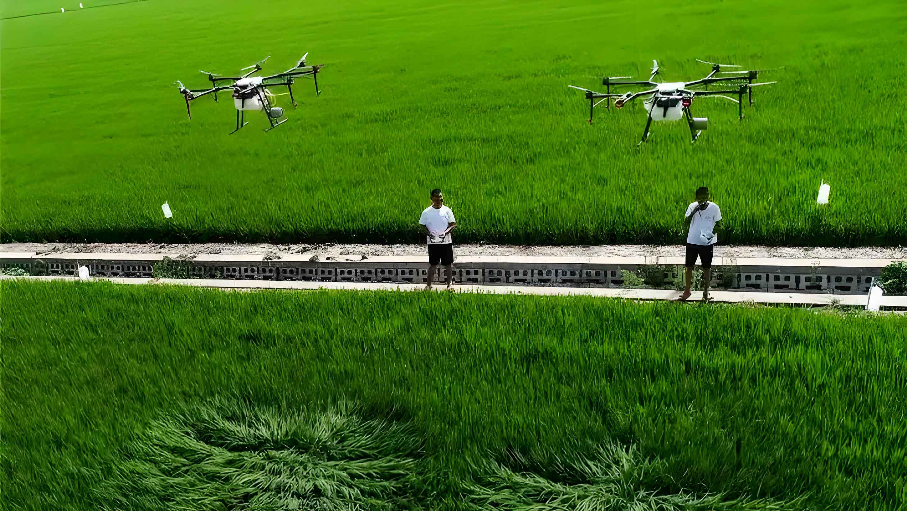
The core objective is to develop a suspension mechanism that allows independent adjustment of the spray boom in pitch and roll directions, based on real-time flight attitude data. This involves collecting field data on the drone’s orientation, mathematically solving for attitude angles, designing a mechanical structure with appropriate adjustment ranges, and validating it through finite element analysis. Throughout this work, the term “agricultural drone” will be frequently highlighted to underscore its relevance in advancing agricultural mechanization. By integrating engineering principles with agricultural needs, this study aims to enhance the operational reliability of single rotor agricultural drones, contributing to more effective and environmentally friendly crop protection strategies.
Flight Attitude Analysis for Agricultural Drones
To understand the impact of flight attitude on spray performance, I first conducted field experiments to collect data on the orientation of a single rotor agricultural drone during operation. The drone was equipped with onboard gyroscopes to record attitude spectra, capturing its motion in a three-dimensional Cartesian coordinate system. In this system, the drone’s attitude is defined by three angles: pitch (rotation around the Z-axis), roll (rotation around the X-axis), and yaw (rotation around the Y-axis). For spray applications, pitch and roll are most critical, as they directly affect nozzle height and alignment, while yaw has minimal influence. The data was gathered during a field trial in an agricultural setting, where the agricultural drone followed a predefined spraying trajectory. This real-world data provides a basis for designing a suspension mechanism that compensates for attitude variations.
The collected attitude spectra were processed using two mathematical methods: Euler angles and quaternions. These approaches are essential for solving the drone’s orientation from sensor data. The Euler angle method involves rotation matrices for each axis. For a rotation by angle θ around the Y-axis, the matrix is:
$$C_0 = \begin{bmatrix} \cos\theta & 0 & -\sin\theta \\ 0 & 1 & 0 \\ \sin\theta & 0 & \cos\theta \end{bmatrix}$$
For a rotation by ψ around the Z-axis:
$$C_1 = \begin{bmatrix} \cos\psi & \sin\psi & 0 \\ -\sin\psi & \cos\psi & 0 \\ 0 & 0 & 1 \end{bmatrix}$$
And for a rotation by φ around the X-axis:
$$C_2 = \begin{bmatrix} 1 & 0 & 0 \\ 0 & \cos\varphi & \sin\varphi \\ 0 & -\sin\varphi & \cos\varphi \end{bmatrix}$$
The overall rotation matrix C is the product of these matrices: C = C₀·C₁·C₂. Using incremental updates, the attitude at each time step can be computed. However, for faster computation, quaternions are often preferred. A quaternion represents rotation with a unit vector e = (x, y, z) and angle γ, defined as q = [q₀, q₁, q₂, q₃] where q₀² + q₁² + q₂² + q₃² = 1. The rotation matrix from quaternions is:
$$R = \begin{bmatrix} q_0^2 + q_1^2 – q_2^2 – q_3^2 & 2(q_1 q_2 + q_0 q_3) & 2(q_1 q_3 – q_0 q_2) \\ 2(q_1 q_2 – q_0 q_3) & q_0^2 – q_1^2 + q_2^2 – q_3^2 & 2(q_2 q_3 + q_0 q_1) \\ 2(q_1 q_3 + q_0 q_2) & 2(q_2 q_3 – q_0 q_1) & q_0^2 – q_1^2 – q_2^2 + q_3^2 \end{bmatrix}$$
Converting quaternions to Euler angles allows for intuitive interpretation:
$$\varphi = \arctan\left(\frac{2(q_2 q_3 + q_0 q_1)}{q_0^2 – q_1^2 – q_2^2 + q_3^2}\right)$$
$$\theta = \arcsin(-2(q_1 q_3 – q_0 q_2))$$
$$\psi = \arctan\left(\frac{2(q_1 q_2 + q_0 q_3)}{q_0^2 + q_1^2 – q_2^2 – q_3^2}\right)$$
Applying these methods to the field data, I solved for the pitch and roll angles over time. The results showed significant variations during operation, which are summarized in the table below. This analysis is crucial for defining the adjustment range of the suspension mechanism in an agricultural drone.
| Attitude Parameter | Angle Range (degrees) | Angular Acceleration Range (degrees/s²) |
|---|---|---|
| Pitch (around Z-axis) | -18 to 18 | -7 to 7 |
| Roll (around X-axis) | -15 to 14 | -8 to 7 |
These ranges indicate that the agricultural drone experiences substantial orientation changes, necessitating a suspension mechanism with sufficient flexibility to maintain spray boom stability. The data also highlights the dynamic nature of agricultural drone operations, where rapid maneuvers can affect spraying precision.
Design of the Spray Boom Suspension Mechanism
Based on the flight attitude analysis, I designed a suspension mechanism that allows the spray boom to adjust independently in pitch and roll directions. The traditional setup fixes the boom directly to the landing gear, causing it to tilt with the drone’s body. To overcome this, I proposed a two-degree-of-freedom system using two revolute joints: one for pitch adjustment and another for roll adjustment. This design ensures that the spray boom remains optimally oriented relative to the crop canopy, regardless of the agricultural drone’s flight attitude.
The design process considered three key factors to ensure practicality and effectiveness. First, the adjustment ranges were determined by expanding the observed attitude angles to account for extreme scenarios. From the data, pitch varied from -18° to 18°, and roll from -15° to 14°. To provide a safety margin, I set the suspension mechanism’s adjustment ranges to -30° to 30° for pitch and -20° to 20° for roll. This ensures that the agricultural drone can handle unexpected attitude fluctuations during field operations. Second, I avoided interference with the drone’s frame and other components. The mechanism was positioned to prevent collision with the fuselage or rotor during full adjustment, and nozzle placement was optimized to avoid the rotor downwash zone. Third, the mechanism was located within the optimal rotor wind field. Research on single rotor agricultural drones indicates that the maximum downwash velocity occurs between 1/4 and 3/4 of the rotor radius, so the suspension was installed in this region to leverage airflow for better spray deposition.
The suspension mechanism consists of several components: a support plate attached to the drone frame, a roll adjustment assembly with gear transmission for high torque handling, and a pitch adjustment assembly with direct motor drive. The use of gear transmission for roll adjustment provides robustness against stress, while the pitch adjustment uses a simpler motorized joint. The control system integrates gyroscope data, which is processed to generate signals that drive the motors, maintaining the spray boom at a set orientation. This active adjustment is vital for precision in agricultural drone spraying. The materials were selected for lightweight and strength, primarily aluminum alloy for structural parts and alloy steel for transmission components. The properties of these materials are summarized in the table below, which guides the subsequent finite element analysis.
| Material | Density (kg/m³) | Elastic Modulus (MPa) | Poisson’s Ratio |
|---|---|---|---|
| Aluminum Alloy | 2.7 × 10³ | 7.0 × 10⁴ | 0.33 |
| Alloy Steel | 7.7 × 10³ | 2.1 × 10⁵ | 0.28 |
The design was modeled using Creo software, ensuring compatibility with ANSYS Workbench for simulation. This step is critical for validating the structural integrity of the agricultural drone’s suspension mechanism before physical prototyping.
Static Analysis of the Suspension Mechanism
To evaluate the structural strength of the suspension mechanism, I performed a static analysis using ANSYS Workbench. The 3D model was imported, meshed with a 5 mm element size, and assigned material properties as defined above. The analysis simulated operational loads, including inertial forces from drone acceleration and reaction forces from spray nozzles. For the agricultural drone, a horizontal acceleration of 10 m/s² was assumed to account for aggressive maneuvers, generating an inertial force F = ma, where m is the mass of the mechanism (1.939 kg excluding the support plate). Thus, F = 19.39 N applied horizontally to the support plate.
Additionally, spray nozzle reaction forces were considered. Using common agricultural drone nozzles like VP110-03 with a pressure of 2 bar (0.2 MPa) and flow rate of 980 mL/min, the reaction force per nozzle is calculated by:
$$F = 0.233 \sqrt{q} \cdot p$$
where q is flow rate in L/min and p is pressure in bar. Substituting values: q = 0.98 L/min, p = 2 bar, gives F ≈ 0.323 N per nozzle. For two nozzles, the total upward force is 0.646 N. Torques due to angular accelerations were also included. The moment of inertia for the spray boom is 8.3 × 10⁻⁴ kg·m² in pitch and 2.4 × 10⁻³ kg·m² in roll. Using T = Iα, with angular accelerations from the data (max 7° /s² for pitch and 8° /s² for roll, converted to rad/s²: 0.122 rad/s² for pitch and 0.140 rad/s² for roll), the torques are:
$$T_{\text{pitch}} = (8.3 \times 10^{-4}) \times 0.122 \approx 0.101 \times 10^{-3} \, \text{N·m}$$
$$T_{\text{roll}} = (2.4 \times 10^{-3}) \times 0.140 \approx 0.336 \times 10^{-3} \, \text{N·m}$$
These loads were applied in the simulation, and the results are summarized below. The static analysis confirms that the suspension mechanism can withstand operational stresses without failure, a key requirement for reliable agricultural drone performance.
| Load Type | Value | Application Point |
|---|---|---|
| Horizontal Inertial Force | 19.39 N | Support Plate |
| Nozzle Reaction Force (total) | 0.646 N | Nozzle Bases |
| Pitch Torque | 0.101 mN·m | Pitch Axis |
| Roll Torque | 0.336 mN·m | Roll Axis |
The stress distribution showed that the maximum von Mises stress occurred on the pitch bracket, with a value of 13.33 MPa. Compared to the allowable stress for aluminum alloy (280 MPa), this indicates a safety factor of approximately 21, meaning the structure is well within safe limits. The deformation was minimal, with maximum displacement under 1 mm, ensuring that the agricultural drone’s spray boom remains stable during operation. This analysis validates the suspension mechanism’s static strength, paving the way for dynamic assessments.
Modal Analysis of the Suspension Mechanism
Beyond static strength, the dynamic behavior of the suspension mechanism is crucial to avoid resonant vibrations that could compromise spray accuracy or structural integrity. I conducted a modal analysis in ANSYS Workbench to determine the natural frequencies and mode shapes of the agricultural drone’s suspension system. The governing equation for free vibration without damping is:
$$[M]\{\ddot{U}(t)\} + [K]\{U(t)\} = 0$$
where [M] is the mass matrix, [K] is the stiffness matrix, and {U} is the displacement vector. Assuming harmonic motion {U(t)} = {U₀} sin(ωt), the eigenvalue problem becomes:
$$([K] – \omega_i^2 [M])\{U_0\} = 0$$
Solving this yields natural frequencies ωᵢ and corresponding mode shapes. For the suspension mechanism, I extracted the first eight non-rigid body modes, as lower frequencies dominate dynamic response. The results are presented in the table below, illustrating the vibrational characteristics essential for agricultural drone design.
| Mode Number | Natural Frequency (Hz) | Primary Deformation Description |
|---|---|---|
| 1 | 6.77 | Spray boom swings along Z-axis, max displacement 54.609 mm |
| 2 | 7.17 | Spray boom swings along Z-axis, max displacement 44.33 mm |
| 3 | 7.44 | Spray boom swings along Z-axis, max displacement 54.477 mm |
| 4 | 9.52 | Spray boom swings along X-axis, max displacement 45.815 mm |
| 5 | 53.49 | Spray boom swings oppositely along X-axis, with bracket deformation |
| 6 | 54.33 | Combined deformation in X and Z axes for spray boom and brackets |
| 7 | 71.24 | Complex Z-axis deformation with one nozzle up and one down, max 60.153 mm |
| 8 | 88.79 | W-shaped deformation along Z-axis for spray boom and brackets |
The modal analysis reveals that natural frequencies increase significantly from the fifth mode onward, indicating higher stiffness in certain directions. The mode shapes show that while the spray boom experiences noticeable displacements (up to 60.153 mm in mode 7), the connecting structures like the pitch and roll brackets deform minimally. This suggests that the suspension mechanism is robust against vibrations, with resonant frequencies likely above typical operational ranges for agricultural drones. However, the spray boom’s flexibility could be optimized by adjusting mounting spacing or using centrifugal nozzles to reduce deformation. Overall, the modal analysis confirms that the design meets vibrational requirements, ensuring stable performance for the agricultural drone during field spraying.
Conclusion
In this study, I have successfully designed and analyzed a suspension mechanism for single rotor agricultural drones to address the issue of spray boom attitude variations during flight. By collecting and solving flight attitude data, I determined that pitch angles range from -18° to 18° and roll angles from -15° to 14°, with angular accelerations up to 8°/s². Based on this, I designed a two-degree-of-freedom mechanism with adjustment ranges of -30° to 30° in pitch and -20° to 20° in roll, incorporating gear transmission for roll and direct motor drive for pitch. The design considers avoidance of frame interference and optimal placement within the rotor wind field, crucial for enhancing the efficacy of agricultural drone operations.
The static analysis demonstrated that the maximum stress of 13.33 MPa on the pitch bracket is well below the aluminum alloy’s allowable stress of 280 MPa, confirming structural safety. The modal analysis revealed natural frequencies from 6.77 Hz to 88.79 Hz, with mode shapes indicating acceptable deformation levels, except for some spray boom flexibility that can be further optimized. These results validate the suspension mechanism’s ability to maintain spray boom stability independently of the agricultural drone’s flight attitude, potentially improving spray uniformity and reducing pesticide waste.
Future work could involve prototyping and field testing to correlate these simulations with real-world performance. Additionally, integrating advanced control algorithms for real-time adjustment based on attitude feedback could further optimize the agricultural drone’s spraying precision. This research underscores the importance of mechanical design in advancing agricultural drone technology, contributing to more sustainable and efficient farming practices. By continuously refining such systems, agricultural drones can play an even greater role in meeting global food security challenges.