The monitoring of large-scale linear infrastructure, such as highways, railways, and power grids, presents a significant challenge across vast territories. Conventional point-based monitoring methods are inadequate for comprehensive hazard screening, while manual inspections are time-consuming and labor-intensive. Optical remote sensing, though useful, is often hindered by weather conditions. In this context, synthetic aperture radar interferometry (InSAR) emerges as a powerful tool due to its all-weather, day-and-night operational capability. While satellite-based InSAR offers wide-area coverage, its spatial resolution and revisit frequency may be insufficient for detailed engineering monitoring. Ground-based systems provide high resolution but lack mobility. Airborne platforms bridge this gap, yet traditional manned aircraft are costly and lack flexibility. The advent of China UAV drone technology offers a transformative solution—combining the high resolution and flexibility of airborne systems with significantly lower operational costs and superior mobility for rapid deployment along linear corridors.
However, a critical challenge in utilizing China UAV drone platforms for repeat-pass InSAR is motion error. Unlike stable satellite orbits or larger aircraft, lightweight UAVs are susceptible to atmospheric turbulence, leading to deviations from the ideal flight path (trajectory errors) and changes in attitude (roll, pitch, and yaw angles). These motion errors introduce phase artifacts during SAR imaging and cause misregistration between repeat-pass images, severely degrading interferometric coherence and ultimately the precision of deformation measurements. This article addresses these challenges by presenting a dedicated data processing chain developed for a China UAV drone-borne InSAR system, focusing on motion error compensation strategies tailored to the characteristics of UAV flights.
Theoretical Framework for UAV Motion Error Mitigation
The core of high-precision repeat-pass InSAR lies in generating a high-quality interferogram from two SAR images acquired over the same area at different times. For a China UAV drone platform, the phase in the interferogram, $\phi$, for a target point can be expressed as the sum of several components:
$$
\phi = \phi_{\text{defo}} + \phi_{\text{topo}} + \phi_{\text{atm}} + \phi_{\text{orbit}} + \phi_{\text{motion}} + \phi_{\text{noise}}
$$
where $\phi_{\text{defo}}$ is the desired deformation phase, $\phi_{\text{topo}}$ is the topographic phase, $\phi_{\text{atm}}$ is atmospheric delay, $\phi_{\text{orbit}}$ is phase due to non-parallel tracks, $\phi_{\text{motion}}$ is the phase error induced by uncompensated platform motion, and $\phi_{\text{noise}}$ is decorrelation noise. Our processing aims to isolate $\phi_{\text{defo}}$ by minimizing $\phi_{\text{motion}}$ and $\phi_{\text{orbit}}$ through tailored methods.
1. Common Heading Angle Fitting for SAR Imaging
A primary source of error in China UAV drone repeat-pass data is the non-parallelism of flight tracks. Even with high-precision navigation, slight differences in yaw angle between passes create a non-parallel spatial baseline. This introduces an azimuth-variant phase component that manifests as dense, azimuth-oriented fringes in the interferogram, obscuring the deformation signal.
Consider the interferometric geometry where the master and slave tracks are not perfectly parallel. The total interferometric phase can be decomposed as:
$$
\phi(x, r, \theta) \approx -\frac{4\pi}{\lambda} B \cos(\theta – \alpha) – \frac{4\pi}{\lambda} x \delta \cos(\theta – \beta)
$$
Here, $x$ is the azimuth coordinate, $r$ is the slant range, $\theta$ is the incidence angle, $\lambda$ is the radar wavelength, $B$ is the baseline length, $\alpha$ is its orientation, and $\delta$ is the small track angle difference. The second term, $-\frac{4\pi}{\lambda} x \delta \cos(\theta – \beta)$, is linearly proportional to the azimuth coordinate $x$. This term causes the azimuth fringes, with their frequency dependent on $\delta$.
To eliminate this, we propose a Common Heading Angle Fitting step during the SAR focusing process (e.g., using an $\omega$-$k$ or chirp-scaling algorithm). Instead of processing each pass independently based on its measured, slightly divergent trajectory, we fit a common reference straight-line trajectory to all passes. The key steps are:
- Trajectory Fitting: The high-frequency positional jitter from the POS (Position and Orientation System) data is filtered out. A linear fit is applied to the smoothed trajectory of each pass to estimate its average heading angle. A common heading angle is derived (e.g., the mean of all passes).
- Motion Compensation onto a Common Geometry: The raw radar echoes from each pass are motion-compensated not onto their actual, wobbly trajectories, but onto parallel tracks defined by the common heading angle and a common start/stop reference point.
- Doppler Centroid Alignment: The Doppler centroid frequencies for each pass are estimated and shifted to a common reference value, ensuring spectral alignment in the azimuth frequency domain.
This method effectively forces the repeat-pass data to conform to an ideal parallel-track interferometric geometry, thereby removing the azimuth-linear phase term $\phi_{\text{orbit}}$ and the corresponding fringes.
2. Block-Wise Registration for Residual Error Compensation
Even after common heading angle fitting, residual motion errors and uncompensated atmospheric path delays can cause complex, spatially-variant offsets between the master and slave images. A global polynomial model for registration often fails to capture these local distortions, leading to residual misregistration and coherence loss. To address this, we employ a Block-Wise Registration technique.
The core idea is to partition the full-resolution SAR image into smaller, contiguous blocks (e.g., $M \times N$ blocks). Within each block, the local offset field is assumed to be smooth and can be modeled by a low-order polynomial. The procedure is as follows:
- Global Coarse Registration: Perform an initial coarse registration using a cross-correlation method in the Fourier domain to align the images globally.
- Control Point Network: Establish a dense network of control points across the master image.
- Local Offset Estimation: For each block, identify reliable control points within it. The local offsets ($\Delta X$, $\Delta Y$) for these points are modeled as a function of their master image coordinates ($x_m$, $y_m$) using a second-order polynomial:
$$
\Delta X = A_0 + A_1 x_m + A_2 y_m + A_3 x_m^2 + A_4 y_m^2 + A_5 x_m y_m
$$
$$
\Delta Y = B_0 + B_1 x_m + B_2 y_m + B_3 x_m^2 + B_4 y_m^2 + B_5 x_m y_m
$$
The coefficients $\mathbf{A} = [A_0, A_1, …, A_5]^T$ and $\mathbf{B} = [B_0, B_1, …, B_5]^T$ are solved for each block using least-squares estimation from the measured offsets of its control points. - Building a Dense Offset Map: The polynomial models from all blocks are used to generate a dense, spatially-varying offset map for the entire scene.
- Fine Resampling: The slave image is resampled according to this dense offset map to achieve sub-pixel alignment with the master image on a local scale.
This block-wise approach adapts to the local deformation of the image geometry caused by residual motion errors, significantly improving the pixel-level alignment and, consequently, the interferometric coherence.
System Overview and Experimental Design
The developed China UAV drone-borne InSAR system integrates three key components:
| Component | Specification | Role in InSAR |
|---|---|---|
| SAR Sensor | X-band, lightweight design (~10 kg) | Generates the radar echoes; X-band provides high spatial resolution sensitive to small deformations. |
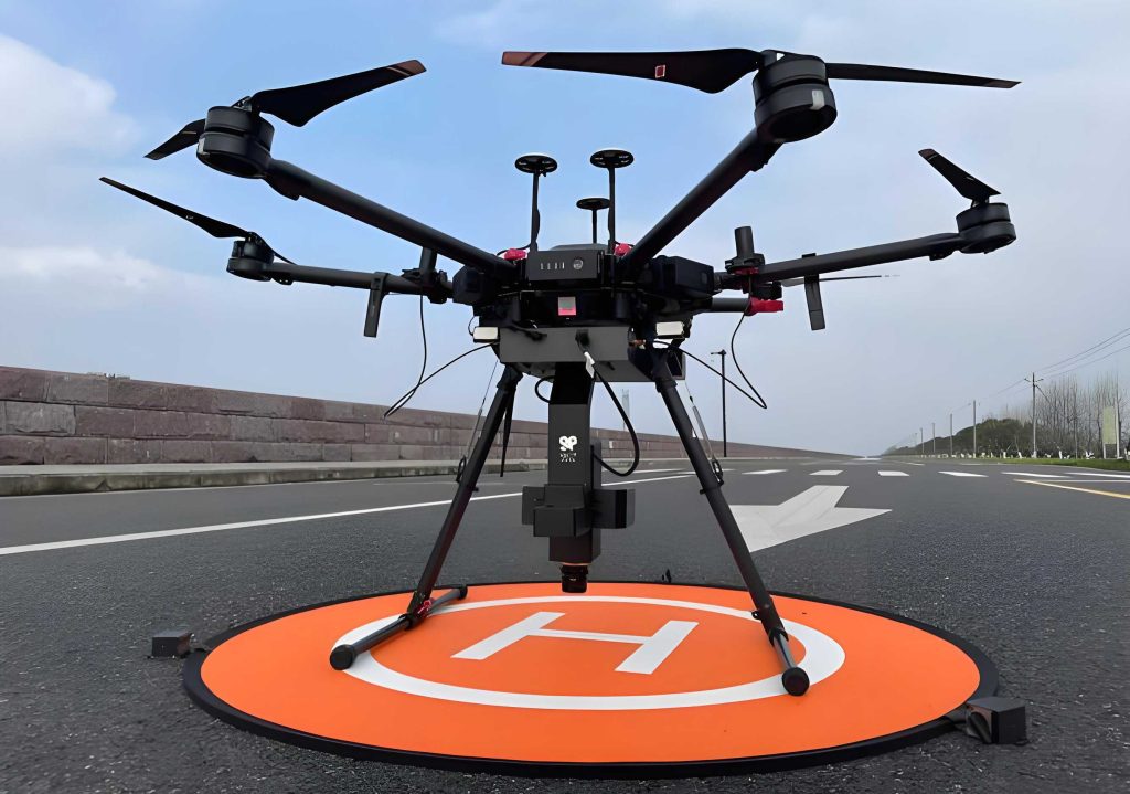
| UAV Platform | Fixed-wing VTOL (Vertical Take-Off and Landing), 25 kg class | Carries the sensor; VTOL offers operational flexibility without runways; fixed-wing ensures stable cruise. |
| POS System | Integrated IMU (Inertial Measurement Unit) & RTK (Real-Time Kinematic) GNSS | Provides precise trajectory and attitude data essential for motion compensation and geo-referencing. |
To validate the deformation monitoring capability of this China UAV drone system and the proposed processing methods, a field simulation experiment was conducted. The test site was a flat, barren area to minimize temporal decorrelation. Two wooden settlement plates (Plate A and Plate B), each 2m × 2m, were placed on the ground and covered with a layer of sand. Under each plate, wooden blocks of 19 mm height were inserted. Differential settlement was simulated by sequentially removing these blocks between successive UAV flights. Corner reflectors were deployed to provide stable phase reference points. Multiple repeat-pass flights were executed, with the platform flying at approximately 1000 m altitude and a 45° look angle. The flight trajectory control was better than ±2 m, which is suitable for repeat-pass interferometry.
Data Processing and Results Analysis
The raw data from the China UAV drone flights were processed using the following chain: 1) Common Heading Angle Fitting SAR Imaging, 2) Block-Wise Registration of image pairs, 3) Interferogram formation, 4) Adaptive Goldstein filtering, 5) Phase unwrapping using Minimum Cost Flow (MCF) algorithm, and 6) Estimation and removal of residual orbital/atmospheric phase trends using a polynomial model.
Effectiveness of Common Heading Angle Fitting
The impact of the common heading angle fitting method is demonstrable. Without it, interferograms from passes with even a minor heading difference (e.g., 0.05°) showed distinct azimuth-running fringes. After applying the method, these systematic fringes were eliminated, resulting in a cleaner interferogram where the phase primarily reflected topography and deformation. The improvement is also quantifiable in terms of average coherence and Doppler centroid alignment.
| Interferometric Pair | Processing Method | Average Coherence | Doppler Centroid Difference (Hz) |
|---|---|---|---|
| Pair 1 | Without Common Heading Fit | 0.64 | 3.87 |
| Pair 1 | With Common Heading Fit | 0.65 | ~0 |
| Pair 2 | Without Common Heading Fit | 0.74 | 10.31 |
| Pair 2 | With Common Heading Fit | 0.78 | ~0 |
Effectiveness of Block-Wise Registration
The block-wise registration method was tested by comparing it against global registration (1×1 block) and different block partitions (e.g., 4×4, 8×8). Performance was evaluated using the Root Mean Square Error (RMSE) of registration offsets and the resulting interferometric coherence.
| Registration Scheme | Offset RMSE (pixels) | Average Coherence | Remarks |
|---|---|---|---|
| Global (1×1) Polynomial | High | ~0.60 | Residual phase slopes, poor alignment in areas of high residual error. |
| 4×4 Block Partition | Medium | ~0.75 | Improved, but some local misregistration persists. |
| 8×8 Block Partition | Low | >0.80 | Best performance. Effectively compensates local distortions, leading to high coherence. |
The results confirm that the block-wise approach, particularly with a finer partition like 8×8, significantly enhances registration accuracy by modeling spatially-variant offsets, thereby boosting the final interferometric coherence from around 0.6 to over 0.8.
Deformation Measurement Accuracy
The ultimate test of the China UAV drone InSAR system and processing chain is the accuracy of measured deformation. The simulated settlement of the plates, projected into the radar Line-of-Sight (LOS), served as ground truth. Multiple differential interferograms were processed for different stages of block removal.
| Simulated Change | Plate | Theoretical LOS Deformation (mm) | Measured LOS Deformation (mm) | Deviation (mm) |
|---|---|---|---|---|
| No change | A | 0.0 | 0.1 | +0.1 |
| No change | B | 0.0 | 0.0 | 0.0 |
| One block removed (both sides) | A | -13.4 | -12.8 | +0.6 |
| One block removed (both sides) | B | -13.4 | -11.5 | +1.9 |
| Two blocks removed (both sides) | A | -26.9 | -25.5 | +1.4 |
| Two blocks removed (both sides) | B | -26.9 | -25.1 | +1.8 |
| Asymmetric removal | A (left side) | 0.0 | -1.2 | -1.2 |
| Asymmetric removal | A (right side) | -13.4 | -13.8 | -0.4 |
The Root Mean Square Error (RMSE) of the deformation measurements for Plate A and Plate B across all interferograms was calculated to be 1.2 mm and 1.5 mm, respectively. All measured deviations were within ±2.6 mm of the theoretical values. This demonstrates that the integrated China UAV drone-borne InSAR system, processed with the proposed methods, achieves millimeter-level precision in deformation monitoring. The high-resolution SAR imagery (0.18 m × 0.18 m) allowed for clear identification and measurement of the small-scale settlement plates.
Discussion and Outlook
The presented work validates a practical and effective data processing methodology for repeat-pass InSAR using a China UAV drone platform. The two-pronged approach—common heading angle fitting during imaging and block-wise registration during interferometry—directly targets the dominant error sources in UAV-based data: track non-parallelism and complex residual motion errors. The field experiment under controlled conditions conclusively proves the millimeter-scale measurement capability.
The success of this China UAV drone technology opens avenues for its application in monitoring linear infrastructure health across the region. Its flexibility allows for targeted, frequent monitoring of high-risk slopes, embankments, or subsidence areas along railways and highways. However, the current experiment was conducted on an ideal, flat, and barren surface. Real-world scenarios involving steep topography, vegetation cover, or urban areas will introduce additional challenges like geometric distortions, temporal decorrelation, and more complex atmospheric effects. Future work will focus on adapting the processing chain for such complex terrains, potentially integrating multi-angle observations from the flexible China UAV drone platform to resolve 3D deformation vectors and further mitigate atmospheric artifacts. Furthermore, the development of real-time or near-real-time processing capabilities will enhance the value of this technology for emergency response and rapid hazard assessment.
Conclusion
This article detailed the development and validation of a specialized data processing method for a China UAV drone-borne repeat-pass InSAR system. By introducing a common heading angle fitting strategy in the SAR imaging stage and a block-wise registration technique in the interferometric processing stage, the method effectively mitigates the critical motion errors inherent to lightweight UAV platforms. The experimental results demonstrate that this approach significantly improves interferometric coherence and enables deformation measurements with millimeter-level accuracy (RMSE < 1.6 mm). The system’s high spatial resolution and the processing chain’s robustness establish China UAV drone-borne InSAR as a highly promising tool for precision deformation monitoring of critical linear infrastructure, offering a unique combination of flexibility, resolution, and cost-effectiveness for engineering and geohazard applications.