
Accurate and efficient land surveying forms the critical foundation for land resource management, agricultural planning, and rural development. Traditional surveying methods, often reliant on satellite imagery or manned aerial photography, face significant challenges in rural contexts, including high costs, inflexible scheduling, and difficulties in achieving the high spatial resolution required for detailed cadastral mapping. The emergence of Unmanned Aerial Vehicle (UAV) technology, particularly when equipped with oblique photography systems, presents a transformative solution. This article, from a practitioner’s perspective, delves into a comprehensive methodology for rural land surveying based on low-altitude UAV drone oblique photography. I will explore the technical principles, detailed workflow, data processing chains, and empirical validation of this approach, demonstrating its superiority in precision, efficiency, and cost-effectiveness for modern geospatial tasks.
1. Introduction: The Need for Advanced Surveying in Rural Areas
Land is a finite and vital resource. In rural regions, precise knowledge of land parcel boundaries, areas, and the spatial distribution of features like farmlands, houses, and roads is essential for land tenure security, agricultural optimization, and sustainable development planning. Conventional surveying techniques, such as ground-based total station measurements or photogrammetry using large-format aerial cameras mounted on manned aircraft, are often time-consuming, labor-intensive, and economically prohibitive for large-scale or frequent rural surveys. Satellite imagery, while offering extensive coverage, is constrained by fixed revisit cycles, cloud cover, and limited ground sampling distance (GSD), making it unsuitable for producing large-scale maps (e.g., 1:500 or 1:1000) needed for cadastral work.
The integration of UAV drones with advanced positioning systems and multi-lens cameras has revolutionized the field of geomatics. A UAV drone offers unparalleled flexibility: it can be deployed rapidly, fly at low altitudes under cloud cover, and capture ultra-high-resolution imagery from multiple angles. Oblique photography, unlike traditional vertical (nadir) photography, involves capturing images with the camera axis tilted, typically at angles between 30° to 60° from the vertical. This technique simultaneously records the tops and sides of objects, such as building façades, fences, and vegetation boundaries, which are crucial for creating true three-dimensional (3D) models and for accurate feature extraction in complex rural environments. The core objective of the methodology discussed here is to establish a streamlined, accurate, and reliable process for rural land surveying by leveraging the synergistic potential of low-altitude UAV drone platforms and multi-view oblique photogrammetry.
2. Technical Foundations of UAV Drone Oblique Photogrammetry
The proposed surveying method is built upon a robust technical framework involving the UAV drone system, sensor configuration, and photogrammetric processing principles.
2.1. The UAV Drone System and Payload
The selection of an appropriate UAV drone platform is paramount. For rural land surveying, fixed-wing or multi-rotor UAV drones are commonly used. Fixed-wing UAV drones offer advantages in covering large, contiguous areas with greater flight endurance, while multi-rotor UAV drones provide superior maneuverability, vertical take-off and landing (VTOL) capability, and stability for precise image capture in areas with varied topography or numerous obstacles.
The payload is the heart of the system. A typical oblique photography system consists of one nadir-facing camera and four or five cameras tilted at specific angles (e.g., 45°). These cameras are rigidly mounted and synchronized to fire simultaneously, capturing a comprehensive set of images from different perspectives for each ground position. Key sensor parameters include:
- Focal Length (f): Typically a wide-angle lens (e.g., 24mm or 35mm on a full-frame equivalent) is used to achieve a large field of view.
- Sensor Pixel Size (p): The physical size of an individual pixel on the camera’s CMOS or CCD sensor, measured in micrometers (µm).
- Image Resolution: The total number of pixels (e.g., 20 Megapixels or higher).
The system is also integrated with a high-precision Global Navigation Satellite System (GNSS) receiver and an Inertial Measurement Unit (IMU), collectively known as a Position and Orientation System (POS). This system records the precise geolocation (X, Y, Z) and attitude (roll, pitch, yaw) of the UAV drone at the moment each image is captured, providing essential initial values for the subsequent aerial triangulation process.
2.2. Photogrammetric Principles and 3D Reconstruction
The fundamental principle behind extracting 3D information from 2D images is photogrammetry, specifically Structure from Motion (SfM) and Multi-View Stereo (MVS) algorithms. The oblique imagery from the UAV drone provides a rich dataset for these algorithms.
- Aerial Triangulation (AT) & Bundle Adjustment: The software automatically identifies matching feature points (tie points) across overlapping images from different angles and positions. Using the known camera calibration parameters (focal length, principal point, lens distortion) and the approximate exterior orientation parameters from the POS data, a robust bundle adjustment is performed. This process refines the precise 3D positions of the tie points and the exact orientation of all camera stations, minimizing the overall reprojection error. The mathematical model for a single image point is based on the collinearity equations:
$$x – x_0 = -f \frac{m_{11}(X – X_0) + m_{12}(Y – Y_0) + m_{13}(Z – Z_0)}{m_{31}(X – X_0) + m_{32}(Y – Y_0) + m_{33}(Z – Z_0)}$$
$$y – y_0 = -f \frac{m_{21}(X – X_0) + m_{22}(Y – Y_0) + m_{23}(Z – Z_0)}{m_{31}(X – X_0) + m_{32}(Y – Y_0) + m_{33}(Z – Z_0)}$$
Where \((x, y)\) are the image coordinates, \((x_0, y_0, f)\) are the interior orientation parameters, \((X_0, Y_0, Z_0)\) are the object space coordinates of the perspective center, \((X, Y, Z)\) are the object space coordinates of the point, and \(m_{ij}\) are the elements of the rotation matrix defined by the attitude angles (ω, φ, κ).
- Dense Point Cloud Generation: After bundle adjustment, MVS algorithms are applied to generate a dense 3D point cloud. Every pixel in the images is evaluated to find corresponding points in overlapping images, resulting in a massive set of 3D coordinates that densely represents the earth’s surface and all objects on it.
- Model Generation: The dense point cloud is then used to construct a triangular irregular network (TIN) or a mesh, which is subsequently textured with the original imagery to produce a photorealistic 3D model. This model serves as the primary data source for measurement and mapping.
3. Methodology: A Detailed Workflow for Rural Land Surveying
The implementation of a UAV drone-based survey follows a structured workflow encompassing pre-flight planning, data acquisition, and post-processing. The following sections detail each stage.
3.1. Pre-Flight Planning and Control Network Establishment
Thorough planning is critical for mission success and data quality.
A. Defining Survey Specifications and Flight Parameters: The required map scale (e.g., 1:500) dictates the necessary Ground Sampling Distance (GSD). The GSD is the distance between two consecutive pixel centers measured on the ground. It is calculated using the formula:
$$GSD = \frac{H \times p}{f}$$
Where \(H\) is the flying height above ground level (AGL), \(p\) is the pixel size, and \(f\) is the focal length. For a 1:500 scale map, a GSD of 1-5 cm is typically required. Based on the desired GSD and camera parameters, the flight altitude \(H\) is determined. For instance, with a camera having a focal length of 35mm, a pixel size of 6.41 µm, and a target GSD of 2 cm, the flight height AGL would be approximately:
$$H = \frac{GSD \times f}{p} = \frac{0.02 \times 0.035}{6.41 \times 10^{-6}} \approx 109 \text{ meters}$$
Other flight parameters are then set:
- Image Overlap: High overlap is essential for robust 3D reconstruction. Forward overlap (along the flight path) is typically set between 80-90%, and side overlap (between adjacent flight lines) between 70-80%.
- Flight Speed: Adjusted to ensure sufficient image exposure without motion blur.
- Flight Path Planning: The area of interest (AOI) is digitized, and flight lines are generated automatically by mission planning software. The lines are oriented to maximize efficiency and coverage, often following the terrain’s main direction. The software also calculates battery consumption and ensures the flight remains within visual line of sight (VLOS) regulations.
B. Ground Control Points (GCPs) and Check Points (CPs): Although PPK/RTK-enabled UAV drones can achieve high positional accuracy, a network of Ground Control Points (GCPs) is still deployed to georeference the model to the desired coordinate system and to provide absolute accuracy control. GCPs are well-defined, high-contrast targets (e.g., painted crosses) placed across the survey area before the flight. Their precise coordinates (X, Y, Z) are surveyed using a high-accuracy GNSS receiver (e.g., RTK-GNSS). Check Points (CPs), which are not used in the bundle adjustment, are also measured to independently validate the final model’s accuracy. A typical distribution is shown below:
| Survey Area Size (Hectares) | Recommended Minimum Number of GCPs | Recommended Number of CPs | Distribution Pattern |
|---|---|---|---|
| 0-10 | 5-8 | 3-5 | Perimeter and center |
| 10-50 | 8-15 | 5-10 | Uniform grid, emphasis on corners |
| >50 | 15+ (1 per 2-5 Ha) | 10+ | Uniform grid with increased density in areas of complex topography |
3.2. Data Acquisition with the UAV Drone
With planning complete, the field operation commences. The UAV drone is deployed to autonomously execute the planned mission. The pilot monitors telemetry data (altitude, speed, battery status, GPS signal) and weather conditions. The oblique photography system automatically captures synchronized sets of images throughout the flight. The process of data collection is visualized in the following operational schematic:
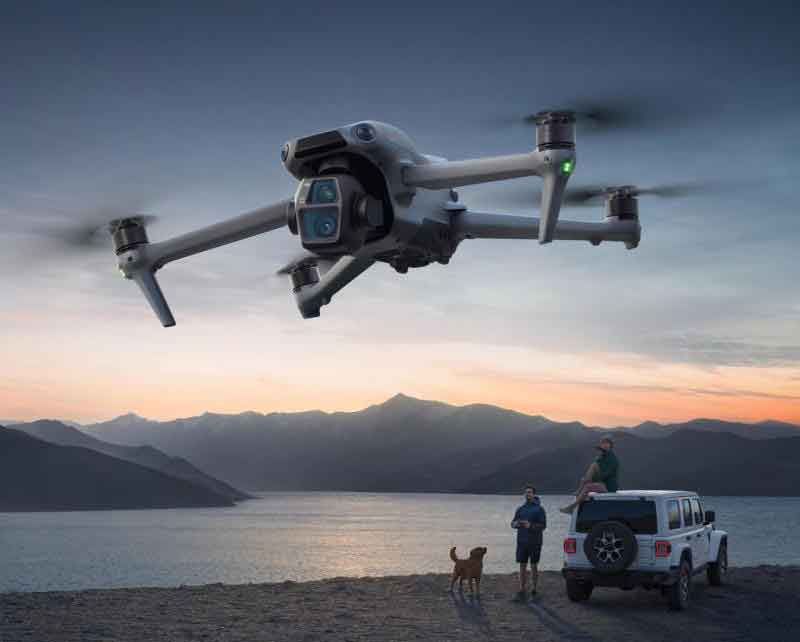
This phase highlights the versatility and automation of the UAV drone platform, capable of systematically capturing comprehensive visual data of the rural landscape from multiple perspectives in a single sortie.
3.3. Post-Processing and Product Generation
This stage transforms raw images into actionable geospatial products.
- Data Import and Initial Processing: Images, along with POS data, are imported into photogrammetric software (e.g., Pix4Dmapper, Agisoft Metashape, ContextCapture). Camera calibration parameters are applied or refined.
- Aerial Triangulation with GCPs: The software performs feature matching and initial bundle adjustment. The surveyed coordinates of the GCPs are then imported, and their corresponding image coordinates are manually or automatically marked. A final bundle adjustment, constrained by the GCPs, is run to produce an optimally accurate and georeferenced sparse point cloud.
- Generation of Dense Cloud, Mesh, and Textured Model: The software generates the dense point cloud and subsequently the 3D mesh and textured model. The accuracy is verified by comparing the model’s coordinates at the Check Point (CP) locations against their known surveyed values. The Root Mean Square Error (RMSE) is calculated:
$$RMSE = \sqrt{\frac{\sum_{i=1}^{n} (M_i – S_i)^2}{n}}$$
Where \(M_i\) is the coordinate measured on the model, \(S_i\) is the surveyed coordinate, and \(n\) is the number of check points. For cadastral-grade surveys, horizontal RMSE should be within 1-2 times the GSD, and vertical RMSE within 1-3 times the GSD.
- Derivative Product Extraction: The accurate 3D model is the source for all final products:
- Digital Surface Model (DSM): Represents the elevation of the topmost surface (ground, buildings, trees).
- Digital Terrain Model (DTM): The bare-earth elevation model, created by manually or automatically classifying and removing non-ground points (buildings, vegetation) from the dense cloud.
- Orthomosaic Map: A geometrically corrected (“orthorectified”) image where every pixel is assigned its true ground coordinate, created by projecting the textured model onto the DTM. This is a true-scale, distortion-free map.
- Digital Line Graph (DLG) / Cadastral Map: This is the primary surveying deliverable. Using the 3D model and the orthomosaic as a stereo-backdrop, operators can digitally delineate (digitize) parcel boundaries, buildings, roads, and other features with high precision in three dimensions. The software allows for direct distance, area, and volume measurements from the model.
The formula for calculating the area of an irregular polygon (like a land parcel) from its vertex coordinates \((X_i, Y_i)\) is applied directly from the digitized data:
$$Area = \frac{1}{2} \left| \sum_{i=1}^{n} (X_i Y_{i+1} – X_{i+1} Y_i) \right|$$
with \((X_{n+1}, Y_{n+1}) = (X_1, Y_1)\).
4. Case Application and Accuracy Validation
To empirically validate the methodology, a project was conducted in a rural area. The objective was to create a detailed cadastral map for land tenure documentation.
Project Setup: A multi-rotor UAV drone equipped with a five-lens oblique camera (nadir, forward, backward, left, right) was deployed. The target GSD was 2.5 cm. A network of 15 GCPs and 8 CPs was established using RTK-GNSS. The UAV drone flew an autonomous mission at 120m AGL, capturing over 2,500 images.
Processing and Results: The data was processed following the workflow above. The bundle adjustment achieved a low re-projection error. The accuracy assessment using the independent CPs yielded the following results:
| Check Point ID | RMSE X (m) | RMSE Y (m) | RMSE Z (m) | Total Horizontal RMSE (m) |
|---|---|---|---|---|
| CP1 | 0.018 | 0.021 | 0.032 | 0.028 |
| CP2 | 0.015 | 0.024 | 0.029 | 0.028 |
| CP3 | 0.022 | 0.019 | 0.035 | 0.029 |
| … | … | … | … | … |
| Average | 0.019 | 0.022 | 0.033 | 0.029 |
The average horizontal accuracy of 2.9 cm (less than 1.2 times the GSD) and vertical accuracy of 3.3 cm fully met the stringent requirements for 1:500 scale cadastral mapping. Parcel boundaries, building footprints, and road edges were digitized from the 3D model with high confidence. A comparative analysis of parcel area calculations between the new UAV drone method and previous survey records showed a high degree of consistency, with discrepancies well within the acceptable tolerance for land registration purposes.
5. Discussion: Advantages, Challenges, and Future Trends
The adoption of low-altitude UAV drone oblique photography for rural land surveying presents a paradigm shift with clear benefits and some evolving challenges.
5.1. Key Advantages
- High Efficiency and Rapid Deployment: A UAV drone can survey hundreds of hectares in a single day, dramatically faster than ground crews.
- Superior Data Richness and Accuracy: Oblique imagery enables the creation of measurable 3D models, improving the interpretation and measurement of vertical features and complex boundaries.
- Cost-Effectiveness: Significant reduction in manpower, time, and equipment costs compared to traditional aerial surveys or exhaustive ground surveys.
- Safety: The UAV drone can access hazardous or difficult terrain without risking surveyors’ safety.
- Comprehensive Products: One flight generates a suite of products (DSM, DTM, Orthomosaic, 3D Model) useful for multiple applications beyond cadastre, such as volumetric analysis, infrastructure planning, and environmental monitoring.
5.2. Persistent Challenges
- Regulatory Compliance: Operating a UAV drone commercially requires adherence to aviation regulations (e.g., licensing, airspace restrictions, privacy laws), which vary by country.
- Environmental Limitations: High winds, rain, or poor lighting can ground flights or degrade data quality.
- Data Processing Expertise and Hardware: Processing thousands of high-resolution images demands skilled operators and powerful computing resources.
- Obstacle Penetration: Dense foliage can obstruct the view of the ground, making it difficult to create an accurate DTM under forest canopies without supplemental LiDAR technology.
5.3. Future Directions
The future of UAV drone-based surveying is intertwined with technological convergence. The integration of LiDAR sensors with UAV drone platforms is already providing solutions for penetrating vegetation and capturing highly accurate terrain models. Advances in artificial intelligence, particularly deep learning, are automating feature extraction (e.g., automatic building footprint delineation, crop type classification) from the generated orthomosaics and 3D models, further reducing manual labor. Furthermore, the development of longer-endurance UAV drones and more efficient processing algorithms in the cloud will continue to expand the scale and scope of feasible projects.
6. Conclusion
The methodology for rural land surveying based on low-altitude UAV drone oblique photography represents a significant technological advancement in the geospatial industry. By providing a detailed examination of the technical principles, systematic workflow, and validation through empirical data, this article has demonstrated that this approach is not only viable but highly advantageous for producing accurate, high-resolution cadastral and topographic data. The ability to rapidly generate true 3D geospatial models and derivative products (orthomosaics, DTMs, DLGs) with centimeter-level accuracy addresses the core needs of modern land administration, agricultural management, and rural development planning. While challenges related to regulation, environment, and data processing persist, the ongoing evolution of UAV drone technology, sensors, and software promises to further solidify this method as the standard for efficient and precise land surveying in rural and beyond. The UAV drone has unequivocally transitioned from a novel tool to an indispensable asset in the surveyor’s toolkit.