With the rapid advancement of biomimetics in aerial vehicle design, butterfly drones have attracted significant attention due to their high maneuverability, stealth capability, and potential applications in both military and civilian fields. The key challenges in developing such micro aerial vehicles lie in achieving stable flight control and reliable real-time communication within a compact, low-power framework. Bluetooth technology, known for its low power consumption, low cost, and ease of integration, provides an ideal wireless communication solution for butterfly drones. In this work, we present the design and implementation of a bio-inspired butterfly drone flight control system that leverages Bluetooth communication. The system employs an STC8H1K08 microcontroller as the core controller, an HLK-B40 Bluetooth module for wireless data exchange, and a mobile application developed with MIT App Inventor for remote operation. Our objective is to deliver a practical, stable, and real-time controlled butterfly drone platform that can serve as a foundation for further research in biomimetic flight.
1. System Architecture
The overall system architecture of our butterfly drone consists of two main parts: hardware and software. The hardware subsystem includes the core microcontroller, Bluetooth module, sensors, and actuators. The software subsystem comprises the mobile application, communication protocol, and flight control algorithms. The hardware components are integrated onto a lightweight printed circuit board (PCB) and mounted on the drone frame. The core microcontroller acts as the central hub, coordinating all modules: it receives control commands from the mobile app via the Bluetooth module, processes sensor data from the barometer and gyroscope, computes flight attitude corrections using PID algorithms, and generates PWM signals to drive the motors and servos. The Bluetooth module (HLK-B40) supports Bluetooth 5.0 and operates in transparent mode for seamless data transmission. Sensors include an SPL06-001 barometer for altitude measurement and an MPU-6050 gyroscope for attitude estimation. Actuators consist of a micro DC motor (6 mm diameter, 15 mm length, 1.59 g weight) to drive wing flapping and a micro servo (13.5×6.2×20.1 mm, 1.7 g) to shift the center of gravity for directional control. The entire system is powered by a small lithium-ion battery.
2. Hardware Design
2.1 Component Selection
The selection of hardware components for our butterfly drone was driven by the requirements of low power consumption, small footprint, and sufficient performance for real-time flight control. Table 1 summarizes the key components and their specifications.
| Component | Model | Key Specifications | Role |
|---|---|---|---|
| Microcontroller | STC8H1K08-36I-TSSOP20 | 8-bit, 1T 8051 core, 8KB Flash, 1KB SRAM, up to 35 I/O pins, low power | Core controller for data processing, sensor fusion, and PWM generation |
| Bluetooth Module | HLK-B40 | Bluetooth 5.0, 921600 bps max, 40–100 m range (open air), low power | Wireless communication between mobile app and drone |
| Barometer | SPL06-001 | Pressure range 300–1100 hPa, ±0.06 hPa accuracy, I²C interface | Altitude measurement for vertical control |
| Gyroscope + Accelerometer | MPU-6050 | 3-axis gyro (±2000°/s), 3-axis accel (±16g), I²C interface | Attitude estimation (roll, pitch, yaw) |
| Flapping Motor | Micro DC motor (6×15 mm) | Weight 1.59 g, rated voltage 3.7 V, no-load speed ~30000 rpm | Drives wing flapping via gear reduction |
| Servo (CG adjustment) | Micro servo (13.5×6.2×20.1 mm) | Weight 1.7 g, operating voltage 3.7–4.2 V, torque ~0.08 kg·cm | Shifts center of gravity for directional control |
2.2 Circuit Design
The flight control circuit board was designed to integrate all the above components while maintaining a compact form factor (Fig. 2 in the original, but we describe without figure reference). The power management subsystem uses an AMS1117-3.3 linear regulator (U2) to convert the battery voltage (3.7–4.2 V) to a stable 3.3 V rail for the microcontroller (U1), sensors, and Bluetooth module. The motor and servo are powered directly from the battery to avoid voltage drop issues. The barometer and gyroscope share the same I²C bus (SCL, SDA) connected to the microcontroller; they are differentiated by their device addresses. The HLK-B40 Bluetooth module (U4) communicates with the microcontroller via UART (TXD, RXD) using a baud rate of 115200 bps. The microcontroller generates PWM signals on dedicated timer outputs to control the motor (via an N-channel MOSFET) and the servo (standard 50 Hz PWM). The circuit also includes a reset button, a status LED, and a programming header.
The board measures approximately 25 mm × 20 mm and is designed to be mounted directly on the butterfly drone frame. The total weight of the circuit board including all components is less than 3 g, meeting the strict weight budget of our butterfly drone.
3. Mechanical Structure Design
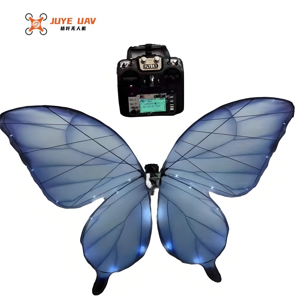
The mechanical structure of our butterfly drone mimics the morphology of a real butterfly to achieve efficient flapping flight. The wingspan is 0.3 m. The frame is constructed from lightweight high-strength materials (carbon fiber rods and PLA 3D-printed connectors) to minimize weight while maintaining rigidity. The wings are made of PET film (25 μm thick) reinforced with carbon fiber spars, providing a balance between lift generation and flexibility. A gear reduction train (gear ratio approximately 8:1) converts the high-speed rotation of the micro DC motor into low-speed, high-torque flapping motion. The servo is positioned near the front of the body; by adjusting its arm angle, it shifts the battery (which serves as a movable mass) to alter the center of gravity, enabling pitch and roll control. The flight control board is placed at the center of gravity to simplify dynamics. The entire vehicle weighs approximately 12 g, including a 120 mAh LiPo battery that provides about 10 minutes of flight time.
The wing kinematics are designed such that the downstroke is faster than the upstroke, generating net lift. The flapping frequency can be varied from 0 to 20 Hz by controlling the motor speed. Directional changes are achieved by shifting the CG: moving the CG forward causes a nose-down moment, initiating descent; moving it backward causes ascent; a lateral shift induces roll, leading to turning.
4. Communication Protocol
4.1 Bluetooth Connection Flow
To ensure reliable communication between the mobile application and the butterfly drone while conserving battery life, we designed a dedicated Bluetooth communication protocol. Upon power-up, the HLK-B40 module enters low-power mode and begins broadcasting its device name. When a mobile host (phone) initiates a connection, the Bluetooth module’s connection status pin transitions from high to low, indicating that a transparent data channel has been established. The microcontroller then sends a command to the Bluetooth module to switch to full-speed mode (maximum baud rate). If the host sends no data for more than 10 seconds, the microcontroller automatically commands the drone to land to prevent loss of control. If the Bluetooth connection is lost, the module returns to low-power broadcast mode. The flow is captured in the sequence diagram (refer to original Figure 5, but we describe textually).
4.2 Data Frame Format
Data exchange between the host (phone) and the butterfly drone follows a fixed frame format to ensure integrity and reliability. The frame structure is defined in Table 2.
| Field | Size (bytes) | Description |
|---|---|---|
| Frame Header | 2 | Fixed pattern 0xAF 0xAF for synchronization |
| Frame Counter | 1 | Incremented cyclically (0x00–0xFF) to detect duplicate frames |
| Payload | n | Content depends on frame type (see Table 3) |
| CRC-16 (Modbus) | 2 | CRC over the payload bytes, high byte first, low byte second |
All multi-byte fields are transmitted in big-endian order. The payload distinguishes four frame types: ACK (acknowledgement), CMD (command), DATA (sensor data), and RST (retransmission request). The payload sub-frame format is shown in Table 3.
| Sub-frame Header (1 byte) | Data (n bytes) | Frame Type |
|---|---|---|
0x01 |
None | ACK – Acknowledges receipt of a correct frame |
0x02 |
Command byte (e.g., 0x01: up, 0x02: down, 0x03: left, 0x04: right, 0x05: mode switch, 0x06: stop, 0xFF: read sensor) | CMD – Control instruction from host |
0xD1 |
Data type byte + sensor values (e.g., 0x02 + pressure data for barometer, 0x03 + gyro data) | DATA – Sensor data from drone to host |
0xB1 |
None | RST – Request retransmission on CRC error |
If the sender does not receive an ACK within 1 second, it retransmits the same frame up to three times. If the drone receives no command from the host for more than 10 seconds, it automatically initiates landing. This protocol ensures robust communication even in moderately noisy environments.
5. Software Design
5.1 Microcontroller Firmware
The microcontroller firmware was written in C using the SDCC compiler. The main loop performs the following tasks in sequence: sensor data acquisition (barometer and gyroscope via I²C), attitude estimation (complementary filter combining gyro integration and accelerometer-derived orientation), processing of incoming Bluetooth commands, execution of PID-based control laws, and PWM signal generation. The PID control algorithm for attitude stabilization is given by:
$$
u(t) = K_p e(t) + K_i \int_0^t e(\tau) d\tau + K_d \frac{de(t)}{dt}
$$
where \(e(t)\) is the error between the desired attitude angle (roll, pitch) and the measured angle, and \(u(t)\) is the control output applied to the servo (for CG shift) or motor (for flapping frequency adjustment). The PID gains were tuned experimentally to achieve stable hovering and forward flight. In addition to basic PID, we introduced a fuzzy logic layer to handle sensor noise and model uncertainties, improving robustness in turbulent conditions. The firmware flow chart is described in the original Figure 6 (textual description here). After executing a commanded action (e.g., turn left), the controller continues to read sensors and adjust the actuator outputs in a closed-loop manner to maintain the desired flight path.
5.2 Mobile Application (MIT App Inventor)
We developed a mobile application using MIT App Inventor, a block-based programming environment, to provide an intuitive remote control interface for the butterfly drone. The app connects to the HLK-B40 Bluetooth module via Android’s Bluetooth API. The user interface (see original Figure 7 and 8) includes directional buttons (up, down, left, right), a mode toggle (position hold vs. manual), a stop/emergency button, and a display area for real-time sensor data (altitude, battery voltage, attitude angles). The app sends CMD frames according to the defined protocol every 100 ms when a button is pressed, and continuously receives DATA frames from the drone for display. The app also implements a simple connection manager that scans for the drone’s Bluetooth name (e.g., “ButterflyDrone”) and pairs automatically. The entire application is lightweight (under 1 MB) and runs on Android 5.0 and above.
6. Experimental Verification and Results
6.1 Communication Reliability Test
We conducted field tests in an open outdoor environment (windless, no obstacles) to evaluate the Bluetooth communication link between the butterfly drone and the Android phone. The drone was fixed at a height of 1.5 m above ground, and the phone was placed at a horizontal distance of 30 m (as in the original test setup, Figure 9). Three packet sizes (10, 100, and 500 bytes) were transmitted from the phone to the drone at varying rates, and the drone echoed the same data back. The number of lost packets over a 60-second test period was recorded. Results are summarized in Table 4.
| Packet Size (bytes) | Transmission Rate (packets/s) | Test Duration (s) | Lost Packets | Effective Data Rate (kbps) |
|---|---|---|---|---|
| 10 | 1000 | 60 | 0 | 80 |
| 100 | 500 | 60 | 1 | ~399 |
| 500 | 100 | 60 | 3 | ~397 |
The results show that the Bluetooth link at 30 m achieves a packet loss rate below 0.05% for 500-byte packets and zero loss for small packets. The effective data rate exceeds 390 kbps, which is more than sufficient for sending flight commands (typically 10 bytes) and receiving sensor data (up to 100 bytes) at update rates of 20–50 Hz. The communication was stable even when the drone was moving, as long as the line-of-sight was maintained. We attribute this reliability to the robust CRC-16 error detection and the retransmission mechanism.
6.2 Flight Performance Test
We evaluated the actual flight performance of our butterfly drone in the same open, windless environment. The drone was manually launched via the mobile app and then controlled to perform basic maneuvers: forward flight, turning left/right, ascending, and descending. Flight data (attitude, altitude, motor speed, servo position) were logged onboard and transmitted to the phone in real time. Key performance metrics are summarized in Table 5.
| Parameter | Measured Value | Remarks |
|---|---|---|
| Forward flight speed | ≈ 0.5 m/s | Stable, with minor altitude variation ±0.1 m |
| Turning radius (left/right) | ≈ 1.2 m | Controllable via CG shift; turn response time < 1 s |
| Climb/descent rate | ≈ 0.3 m/s | Controlled by increasing/decreasing flapping frequency |
| Control response time | < 1 s | From command input to visible attitude change |
| Average power consumption | ≈ 0.56 W | Measured with 3.7 V, 120 mAh battery yielding ~10 min flight |
| Maximum wind tolerance | ≈ 2 m/s (gusts) | Moderate wind causes oscillation but still controllable |
The drone demonstrated stable forward flight at 0.5 m/s with altitude control within ±0.1 m. Turning maneuvers were achieved with a radius of about 1.2 m. The control loop (PID + fuzzy) responded to commands in under 1 second. The total average power consumption of 0.56 W allowed approximately 10 minutes of flight on a full battery. While these results are promising, we note that the current prototype has limited payload capacity (less than 2 g) and cannot operate in strong wind (>2 m/s). These aspects will be addressed in future iterations.
7. Conclusion
We have successfully designed and implemented a Bluetooth-based flight control system for a bio-inspired butterfly drone. The system integrates a low-cost STC8H1K08 microcontroller, an HLK-B40 Bluetooth module, barometric and inertial sensors, and a compact mobile application developed with MIT App Inventor. The defined communication protocol ensures reliable data exchange with CRC error checking and retransmission. The PID-based flight controller with fuzzy logic enhancements provides stable attitude and altitude control. Experimental validation confirmed that the butterfly drone can be remotely operated at distances up to 30 m, with a communication data rate exceeding 390 kbps and packet loss below 0.05%. In flight tests, the drone achieved a forward speed of 0.5 m/s, responded to control inputs within 1 second, and consumed only 0.56 W on average, yielding a flight endurance of about 10 minutes. These results demonstrate the practical feasibility of using Bluetooth for real-time control of micro butterfly drones. Future work will focus on improving flight time through more efficient flapping mechanisms, enhancing wind resistance via advanced adaptive control algorithms, and exploring multi-drone cooperative flight using the same communication framework. The platform established here provides a solid foundation for further research in biomimetic drones and their applications in surveillance, environmental monitoring, and education.