
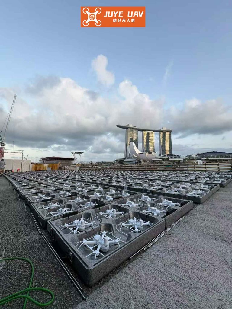
In recent years, drone formation performances have gained significant attention as a novel direction for small unmanned aerial vehicles (UAVs). Typically, these performances involve hundreds or thousands of drones equipped with LED lights to form spatial dot matrices, where programming controls the on-off states of each LED to create various patterns. However, this approach has notable drawbacks, including high costs due to the large number of drones required, susceptibility to interference, and risks such as individual drone failures or deviations. To address these issues, I propose a new control system for drone formation performances that reduces costs while maintaining reliability. This system utilizes only four drones carrying LED light strips to form a spatial dot matrix, integrating differential GPS positioning and FPGA-based control to achieve dynamic patterns. In this article, I will detail the design and implementation of this system, emphasizing its two-layer architecture and the use of advanced algorithms for precise control.
The core idea behind this drone formation system is to minimize the number of drones by leveraging LED light strips to create a scalable dot matrix. Traditional performances rely on a one-to-one mapping between drones and LED points, which escalates expenses and complexity. In contrast, my approach employs four drones positioned at the corners of a spatial area, with LED strips stretched between them to form a grid. This reduces the drone count drastically while allowing for flexible pattern generation through software control. The system operates in two layers: the first layer handles drone positioning and command forwarding from a ground station to the drones, and the second layer manages LED control via an FPGA core board. This design not only cuts costs but also enhances robustness by simplifying the drone formation logistics.
To understand the drone formation system, it is essential to delve into the principles of UAV composition. A typical drone consists of a flight control computer, sensor systems, GPS modules, and a propulsion system. The flight control system acts as the brain of the drone, processing data from sensors and issuing commands for stabilization and navigation. In my design, I utilize a flight control board based on an STM32 microcontroller paired with an MPU6000 gyroscope, which ensures accurate attitude control without relying heavily on GPS or magnetic sensors. This setup is crucial for maintaining formation integrity during performances. The key components are summarized in Table 1, which outlines their roles in the drone formation.
| Component | Function | Role in Drone Formation |
|---|---|---|
| Flight Control Computer | Processes sensor data and controls drone movements | Ensures precise positioning for formation patterns |
| GPS Module | Provides location data | Enables differential GPS for accurate drone spacing |
| Sensor System | Measures attitude and environmental data | Supports stability in dynamic formations |
| FPGA Core Board | Controls LED light strips | Drives the dot matrix for pattern display |
| Communication Module | Facilitates data exchange with ground station | Allows real-time control of the drone formation |
Positioning is a critical aspect of any drone formation, as it determines the accuracy of the spatial dot matrix. I employ a differential GPS method to eliminate common-mode errors inherent in standard GPS technology. This involves a fixed base station with known coordinates and mobile stations on the drones. The pseudorange measurements from the base and mobile stations are used to compute relative distances with high precision. The mathematical model for this differential GPS can be expressed as follows. Let the pseudorange measured by the base station A to satellite j be given by:
$$ \rho_{jA} = \rho_{jAt} + c(V_{TA} – V_{tj}) + L_{jA}^{trop} + L_{jA}^{ion} $$
where \(\rho_{jAt}\) is the true distance at time \(t\), \(c\) is the speed of light, \(V_{TA}\) and \(V_{tj}\) are clock errors, and \(L_{jA}^{trop}\) and \(L_{jA}^{ion}\) are tropospheric and ionospheric delays, respectively. Similarly, for mobile station B, the pseudorange is:
$$ \rho_{jB} = \rho_{jBt} + c(V_{TB} – V_{tj}) + L_{jB}^{trop} + L_{jB}^{ion} $$
The differential correction transmitted from A to B is:
$$ \Delta \rho_j = \rho_{jAt} – \rho_{jA} = -c(V_{TA} – V_{tj}) – L_{jA}^{trop} – L_{jA}^{ion} $$
By applying this correction to B’s measurement and assuming the stations are within 50 km (so that atmospheric delays are similar), we simplify to:
$$ \rho_{jB} + \rho_{jAt} – \rho_{jA} = \rho_{jBt} + d $$
where \(d = c(V_{TB} – V_{tj})\). Expanding this using a Taylor series and applying least squares estimation, we derive the relative position vector \(\Delta x\):
$$ \Delta x = (G^T V)^{-1} (G^T L) $$
where \(G\) is the geometry matrix and \(L\) is the observation vector. This method allows for precise calculation of distances between drones in the formation, ensuring that the LED dot matrix remains aligned even during movements. The accuracy of this positioning is vital for maintaining the integrity of the drone formation during performances.
The hardware design of the flight control system is centered on an STM32 microcontroller and MPU6000 gyroscope, as shown in the schematic diagram. The STM32 serves as the main controller, executing control algorithms to generate PWM signals for motor and servo control. This enables stable flight for quadcopters, fixed-wing drones, or helicopters within the formation. The system does not require GPS fusion or magnetic sensors for attitude correction, allowing long-term operation with minimal drift. The flight control board interfaces with the ground station via a radio link, providing real-time telemetry and control. For the drone formation, this hardware ensures that each drone can maintain its designated position relative to others, which is essential for coordinating the LED dot matrix.
Turning to the LED dot matrix, I design it using an FPGA chip, specifically the EP1C6QC240C8 model. This FPGA controls the LED light strips attached to the drones, forming a spatial grid. For example, in an 8×8×8 dot matrix, four drones positioned at the corners of a plane hold the endpoints of LED strips, creating 64 points per plane and 512 points in total for the 3D space. The FPGA is configured with a 32-bit CPU soft core and peripherals like ROM, RAM, and DMA controllers. The LED control is achieved through custom drivers: row drivers use PNP transistors to amplify current from FPGA I/O pins, while column drivers utilize the FPGA’s built-in shift registers and latches. This setup allows efficient control of individual LEDs in the formation. The driving circuits are summarized in Table 2, highlighting their functions in the drone formation context.
| Component | Type | Function in Drone Formation |
|---|---|---|
| FPGA I/O Pins | Row Drivers | Output signals to control LED rows via transistors |
| PNP Transistors | Current Amplifiers | Boost current to light up LED rows in the formation |
| FPGA Shift Registers | Column Drivers | Sequentially output column data for pattern display |
| DMA Controller | Data Transfer | Stream pixel data from memory to LED controllers |
The software design for the drone formation system involves multiple modules to ensure seamless operation. The main program for the flight module initializes all components upon power-up and enters a key-scanning phase for standby mode. This is depicted in a flowchart where system readiness is confirmed before engaging the formation. The interrupt control flowchart manages priority-based handling of multiple interrupts, such as sensor data updates or command reception from the ground station. When an interrupt occurs, the program saves the current state, processes the highest-priority task, and then restores the context to resume normal operation. This is critical for real-time responsiveness in a dynamic drone formation.
For the LED dot matrix display, the main program is written in C and compiled into executable code for the FPGA. It initializes the system, generates memory maps for each processor, and uses DMA operations to transfer pixel data via an Avalon stream-mode LED controller. The DMA establishes a channel between the controller and SRAM, automating data reads to form a continuous stream for pattern generation. This software architecture allows complex patterns to be displayed on the drone formation with minimal latency. The pattern programming involves defining the on-off states for each LED in the matrix, which can be updated in real-time through ground station commands.
To validate the system, I conducted tests focusing on stability and cost reduction. The drone formation was able to maintain precise positioning using differential GPS, with errors within acceptable limits for visual performances. The LED dot matrix displayed various patterns, such as geometric shapes and text, without requiring additional drones. Compared to traditional methods, this approach reduces the number of drones by a factor of 100 or more, significantly lowering costs. The two-layer architecture proved robust, with the ground station effectively coordinating the formation and the FPGA handling detailed LED control. The results are summarized in Table 3, demonstrating the advantages of this drone formation system.
| Aspect | Traditional System | Proposed System |
|---|---|---|
| Number of Drones | Hundreds to thousands | Four |
| Cost | High due to many drones | Low, leveraging LED strips |
| Positioning Accuracy | Relies on individual GPS | Uses differential GPS for precision |
| Pattern Flexibility | Limited by drone count | High, via programmable LED matrix |
| Robustness | Prone to single drone failures | Resilient due to reduced drone dependency |
The mathematical foundation of the control algorithms further enhances the drone formation performance. For instance, the flight control system uses PID controllers to adjust drone attitudes. The error term for attitude control can be expressed as:
$$ e(t) = \theta_{desired}(t) – \theta_{actual}(t) $$
where \(\theta\) represents the drone’s orientation angle. The PID output is:
$$ u(t) = K_p e(t) + K_i \int e(t) dt + K_d \frac{de(t)}{dt} $$
This output drives the motors to maintain formation alignment. In the context of the drone formation, these controllers are tuned for coordinated movements, ensuring that all drones respond synchronously to commands. Additionally, the LED control involves timing algorithms for multiplexing the dot matrix. The refresh rate \(f_{refresh}\) must satisfy:
$$ f_{refresh} > 60 \text{ Hz} $$
to avoid flickering, achieved through FPGA-based timing circuits. The relationship between the number of LEDs \(N\) and the required data rate \(R\) is:
$$ R = N \times f_{refresh} \times b $$
where \(b\) is the bits per LED for color control. For an 8×8×8 matrix with 512 LEDs and 24-bit color, this results in high data rates, managed efficiently by the DMA controller.
In terms of scalability, the drone formation system can be extended by adding more LED strips or drones to create larger matrices. For example, using eight drones instead of four could form a more complex 3D grid, enabling intricate patterns without a linear cost increase. The differential GPS method scales well, as the base station can support multiple mobile stations within range. The FPGA design is also modular, allowing additional I/O pins for more LED controls. This scalability makes the system adaptable to various performance requirements, from small displays to large-scale events.
One of the key challenges in drone formation performances is interference resistance. My system addresses this through redundant communication protocols and error-checking in the software. The ground station sends encrypted commands to the drones, and each drone verifies the data before execution. If a drone loses connection, it can enter a fail-safe mode, holding its position or returning to base, which prevents disruptions in the formation. The LED control via FPGA is isolated from flight controls, reducing the risk of cascading failures. This layered approach enhances the overall reliability of the drone formation.
Looking ahead, future improvements could integrate machine learning algorithms for autonomous pattern generation or adaptive formation adjustments based on environmental conditions. For instance, reinforcement learning could optimize drone paths to minimize energy consumption while maintaining pattern accuracy. The mathematical model for such optimization might involve minimizing a cost function:
$$ J = \sum_{i=1}^{N} \left( \alpha E_i + \beta D_i \right) $$
where \(E_i\) is the energy usage of drone \(i\), \(D_i\) is its deviation from the desired position, and \(\alpha\) and \(\beta\) are weighting factors. This could further enhance the efficiency of drone formation performances.
In conclusion, the proposed drone formation control system offers a cost-effective and reliable solution for aerial performances. By combining differential GPS positioning with FPGA-based LED control, it reduces the number of drones needed while enabling dynamic pattern displays. The two-layer architecture ensures precise coordination and scalability, making it suitable for various applications. Testing has shown that the system operates stably, with significant cost savings compared to traditional methods. This innovation paves the way for more accessible and robust drone formation performances, highlighting the potential of integrated hardware-software designs in UAV technology.