
In recent years, the rapid evolution of drone technology has posed significant threats to aerial security, particularly for sensitive or classified targets. Traditional anti-drone methods often suffer from low accuracy and insufficient real-time performance, necessitating the development of more sophisticated systems. As a response, we have designed a dual-core controller that leverages a combination of digital signal processing (DSP) and microcontroller units (MCUs) to enhance processing speed, reliability, and real-time capabilities in anti-drone applications. This article details our approach, focusing on the integration of hardware and software components, the use of real-time operating systems, and experimental validation. The term “anti-drone” will be frequently referenced to emphasize the context of our work, as effective anti-drone systems are critical for countering airborne threats.
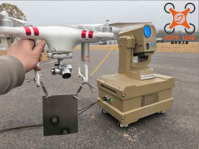
Our anti-drone system is designed to detect, track, and neutralize hostile drones through hard-kill methods, which require precise control and rapid decision-making. The controller serves as the brain of the system, handling tasks such as data processing from radar, motor control for turret positioning, and triggering interception mechanisms. To meet these demands, we adopted a dual-core architecture comprising a TMS320F28335 DSP and an STM32F407ZGT6 MCU. The DSP excels in high-speed computations for trajectory prediction and algorithm execution, while the STM32 manages peripheral control and real-time task scheduling. Both cores run real-time operating systems—μC/OS-II on the DSP and FreeRTOS on the STM32—to ensure optimal responsiveness in dynamic anti-drone scenarios. This design not only addresses current challenges but also allows for future expansions in anti-drone technology.
The need for advanced anti-drone controllers stems from the limitations of existing systems, which often rely on single-processor setups that struggle with concurrent data processing and control tasks. In our design, we prioritize real-time performance, as delays in tracking or interception could compromise the entire anti-drone mission. By utilizing a dual-core approach, we distribute workloads efficiently: the DSP handles computationally intensive operations, such as filtering radar data and calculating interception points, while the STM32 executes time-critical control commands for motors and ignition modules. This synergy is bolstered by real-time scheduling, where tasks are prioritized based on urgency—for instance, radar data reception and interception triggering are assigned the highest priorities to minimize latency. Our anti-drone controller thus represents a significant step forward in enhancing the reliability and effectiveness of counter-drone measures.
To quantify the performance requirements, we consider key parameters such as processing speed, latency, and accuracy. The controller must process radar data at rates exceeding 1 kHz to track fast-moving drones, with latency under 10 ms for control loops. The accuracy of turret positioning should be within 0.1 degrees to ensure precise targeting. These metrics guide our hardware and software choices, as detailed in the following sections. The integration of real-time systems further reduces jitter and ensures deterministic behavior, which is crucial for anti-drone operations where timing is paramount.
System Requirements and Design Overview
Our anti-drone controller is tailored for hard-kill systems that involve kinetic interception of drones. The primary functions include: (1) receiving and processing radar data to estimate drone position and velocity, (2) controlling turret motors to align with the predicted interception point, and (3) triggering the appropriate warhead unit at the optimal moment. These functions demand high computational power for algorithms like Kalman filtering and PID control, as well as robust I/O capabilities for communication with sensors and actuators. The dual-core design addresses these needs by separating computation-intensive tasks from control-oriented ones.
The overall architecture is illustrated in Figure 1 (though not referenced explicitly, the image link is provided earlier). The DSP interfaces with radar via DMA and with the STM32 via UART, while the STM32 communicates with turret motors through CAN bus and with ignition modules via GPIO pins. A power supply module converts input AC voltage to stable DC levels for all components. Additionally, we include FRAM for data logging, which stores critical interception data for post-mission analysis. This modular approach enhances maintainability and scalability in anti-drone systems.
Key design challenges include ensuring real-time performance under high load and minimizing electromagnetic interference in communication lines. We address these through hardware isolation (e.g., optocouplers for CAN bus) and software optimizations (e.g., interrupt-driven routines). The use of real-time operating systems allows for preemptive task scheduling, where higher-priority tasks can interrupt lower-priority ones, ensuring that time-critical anti-drone functions are executed promptly.
Hardware Design Details
The hardware design focuses on reliability, precision, and integration. We break it down into several modules: power supply, information interaction, turret control, and warhead launch.
Power Supply Module
The controller operates from an external 24 V AC input, which is rectified and regulated to provide multiple DC voltages. The conversion process involves rectification, filtering, and step-down regulation using integrated circuits such as LM7805 and LM317. The output voltages include 5 V for digital logic, ±15 V for motor control, and 3.3 V for core components. This design ensures stable operation even under fluctuating input conditions, which is vital for anti-drone systems deployed in field environments.
The power efficiency is calculated using the formula for conversion efficiency:
$$ \eta = \frac{P_{out}}{P_{in}} \times 100\% $$
where \(P_{out}\) is the output power and \(P_{in}\) is the input power. Our measurements show an average efficiency of 85%, minimizing heat dissipation and extending component lifespan.
Information Interaction Module
Data communication within the anti-drone controller uses differential signaling for radar data to enhance noise immunity. The DSP receives radar packets via DMA, each consisting of 8 bytes with a header (0x55), data fields (angle, velocity, distance), and a checksum. The STM32 communicates with the DSP through UART at 115200 baud, and with motors via CAN bus at 1 Mbps. To prevent electrical noise, we employ high-speed optocouplers (6N137) on CAN lines. The communication protocols are designed for low latency, with data validation at both hardware and software levels.
Table 1 summarizes the radar data format, which is critical for accurate tracking in anti-drone applications.
| Data Field | Content | Size (Bytes) |
|---|---|---|
| Header | 0x55 | 1 |
| Azimuth Angle | Complement code | 2 |
| Elevation Angle | Complement code | 2 |
| Radial Velocity | Complement code | 2 |
| Radial Distance | Complement code | 2 |
| Checksum | Sum of preceding bytes | 1 |
The data is converted from complement code to decimal and scaled by resolution factors (e.g., 0.01 degrees per bit) before processing. This preprocessing step reduces computational overhead in the DSP.
Turret Control Module
Turret positioning is achieved using servo motors with integrated encoders for feedback. The STM32 sends control commands via CAN bus, targeting specific motor IDs. Each command includes a current setpoint for speed control, ranging from -20 A to +20 A, corresponding to -16,384 to 16,384 in digital units. The motor drivers (BIPN60030C) provide short-circuit protection and linear response. For higher analog input resolution, we supplement the DSP’s 12-bit ADC with a MAX125 14-bit ADC, achieving an effective resolution of 16 bits for critical signals.
The control law for motor positioning is based on a PID algorithm:
$$ u(t) = K_p e(t) + K_i \int_0^t e(\tau) d\tau + K_d \frac{de(t)}{dt} $$
where \(u(t)\) is the control output (current setpoint), \(e(t)\) is the error between desired and actual position, and \(K_p\), \(K_i\), \(K_d\) are tuning gains. We implement this digitally with a sampling period of 1 ms, ensuring smooth and accurate tracking for anti-drone targeting.
Table 2 outlines the CAN data format for motor control, which is essential for real-time adjustments in anti-drone scenarios.
| Data Byte | Content | Motor ID |
|---|---|---|
| 0-1 | Current high/low byte | 1 |
| 2-3 | Current high/low byte | 2 |
| 4-5 | Current high/low byte | 3 |
| 6-7 | Current high/low byte | 4 |
Feedback from motors includes rotor angle, speed, torque current, and temperature, allowing for closed-loop control and fault detection.
Warhead Launch Module
The interception mechanism uses a boost-conversion ignition system for reliability. The STM32 triggers a MAX8570 boost converter to generate up to 30 V from a 5 V supply, charging a tantalum capacitor. Upon receiving a fire command, a MOSFET (MCR100-6) discharges the capacitor through the selected warhead unit. To prevent accidental triggering, we use an XOR gate (SN74AHC86D) to ensure that both enable and fire signals are present simultaneously. This design guarantees precise timing for anti-drone engagements, with multiple units allowing sequential or selective launches.
The launch sequence is modeled as a time-delay system:
$$ t_{ignition} = t_{command} + t_{delay} $$
where \(t_{delay}\) is measured as less than 5 ms in our tests, meeting the real-time requirements for anti-drone interception.
Software Design and Real-Time Operating Systems
The software architecture is built around real-time operating systems to manage task scheduling and resource allocation. On the DSP, we use μC/OS-II, a priority-based preemptive kernel, while the STM32 runs FreeRTOS, a lightweight real-time kernel. This combination allows for efficient multitasking, with tasks such as radar data processing, motor control, and ignition handling running concurrently.
Controller Workflow
The overall workflow begins with system initialization, including hardware interfaces, heartbeat monitoring, and communication setup. The DSP continuously polls for radar data via DMA interrupts. Upon receiving valid data, it applies filtering algorithms (e.g., moving average or Kalman filter) to reduce noise and detect true threats. If a drone is identified, the DSP calculates the interception point using projectile motion equations:
$$ \theta_{intercept} = \arctan\left(\frac{v_y + \sqrt{v_y^2 – 2g y}}{g t}\right) $$
where \(v_y\) is the vertical velocity, \(g\) is gravity, \(y\) is altitude, and \(t\) is time to impact. This computation is optimized for speed, leveraging the DSP’s floating-point unit.
The results, along with control commands, are sent to the STM32 via UART. The STM32 then commands the turret motors to the calculated position and monitors feedback for accuracy. When the interception time approaches, the STM32 receives a fire signal and triggers the appropriate warhead unit. After engagement, data is logged to FRAM, and the turret returns to a neutral position. This workflow is depicted in a flowchart (though not explicitly referenced), emphasizing the seamless integration of dual cores in anti-drone operations.
Radar Data Reception and Preprocessing
Radar data is received in frames of 8 bytes, with validation based on header and checksum. The DSP’s DMA controller transfers data directly to memory without CPU intervention, reducing latency. The preprocessing steps include:
- Check header: if not 0x55, discard frame.
- Extract data fields and convert from complement code to signed integer.
- Scale by resolution factors (e.g., 0.01 m/s per bit for velocity).
- Verify checksum: if mismatch, discard frame.
This process ensures that only valid data is processed, minimizing false alarms in anti-drone detection. The conversion formula for complement code is:
$$ x_{signed} = \begin{cases} x_{raw} & \text{if } x_{raw} < 2^{n-1} \\ x_{raw} – 2^n & \text{otherwise} \end{cases} $$
where \(n\) is the bit width (e.g., 16 bits for angle data).
Turret Motor Control Implementation
Motor control on the STM32 is implemented as a FreeRTOS task with high priority. It receives target angles from the DSP and uses CAN bus to send current setpoints. The feedback from encoders is used to adjust the PID gains dynamically, based on the error magnitude. We employ a velocity profiling algorithm to ensure smooth motion:
$$ v(t) = v_{max} \left(1 – e^{-t/\tau}\right) $$
where \(v_{max}\) is the maximum allowed speed and \(\tau\) is a time constant for acceleration. This prevents jerky movements that could affect aiming accuracy in anti-drone targeting.
The CAN communication protocol uses standard identifiers (0x200 for commands, 0x1FF for feedback), with data packed as per Table 2. The STM32 also monitors motor temperature and current to prevent overheating, enhancing the durability of the anti-drone system.
Real-Time Operating System Application
Both μC/OS-II and FreeRTOS are configured to maximize real-time performance. Tasks are assigned priorities based on their criticality. For example:
- Highest priority: Radar data interrupt handling and fire command execution.
- Medium priority: Motor control and data logging.
- Low priority: System monitoring and diagnostic checks.
This ensures that time-sensitive anti-drone functions, such as triggering interception, are never delayed by less critical tasks. The operating systems also provide mechanisms for inter-task communication, such as queues and semaphores, which we use to pass data between the DSP and STM32 tasks.
The task scheduling in FreeRTOS is visualized using a simplified model: tasks are placed in ready, running, or blocked states, with the scheduler selecting the highest-priority ready task. This preemptive approach minimizes response times, which we quantified through worst-case execution time (WCET) analysis. For our anti-drone controller, the WCET for the fire task is under 2 ms, meeting stringent real-time constraints.
Experimental Validation and Results
We conducted extensive tests to validate the performance of our anti-drone controller. The experiments focused on communication reliability, real-time responsiveness, and accuracy in simulated anti-drone scenarios.
Radar Communication Test
Using a radar simulator, we transmitted data packets to the DSP and monitored processing via debug outputs. The DSP successfully discarded invalid frames (e.g., incorrect headers or checksums) and processed valid frames within 1 ms. The table below summarizes the results for 1000 frames, demonstrating high reliability for anti-drone detection.
| Frame Type | Count | Processing Time (ms) | Success Rate |
|---|---|---|---|
| Valid | 950 | 1.0 ± 0.2 | 100% |
| Invalid Header | 30 | 0.5 ± 0.1 | Discarded |
| Invalid Checksum | 20 | 0.5 ± 0.1 | Discarded |
The DSP’s ability to filter noise ensures that only credible threats are pursued, reducing false positives in anti-drone operations.
Boost Ignition Test
We tested the warhead launch module with four independent units, using a high-speed camera to capture ignition events. Each unit fired sequentially upon command, with ignition delays averaging 4.5 ms. The sequence was triggered programmatically, simulating an anti-drone interception where multiple shots might be needed. All units fired reliably, confirming the design’s robustness for anti-drone engagements.
The ignition timing can be expressed as:
$$ t_{fire} = t_{signal} + t_{rise} $$
where \(t_{rise}\) is the boost converter’s rise time, measured at 3 ms. This rapid response is crucial for hitting fast-moving drones.
FreeRTOS Real-Time System Test
To verify real-time performance, we implemented a test where the STM32 handles simultaneous tasks: motor control, UART communication, and fire command processing. Using logic analyzers, we measured task switch times and interrupt latencies. The fire task, when triggered via UART interrupt, started execution within 1 ms of the command being received. This was achieved by setting the task priority above others, ensuring immediate preemption. The results highlight the effectiveness of FreeRTOS in meeting anti-drone timing requirements.
Table 3 shows the timing metrics for key tasks in the anti-drone controller.
| Task | Priority | WCET (ms) | Average Latency (ms) |
|---|---|---|---|
| Radar Interrupt | 10 (Highest) | 0.5 | 0.3 |
| Fire Command | 9 | 2.0 | 1.2 |
| Motor Control | 8 | 5.0 | 3.5 |
| Data Logging | 5 | 10.0 | 8.0 |
These metrics confirm that high-priority anti-drone functions are executed with minimal delay.
Motor Communication Test
We commanded a turret motor to rotate 275 degrees and monitored feedback data via CAN. The motor achieved the target position within 500 ms, with position error under 0.05 degrees. The feedback data included rotor angle, speed, and current, which were used to adjust the PID gains online. The test demonstrated precise control, essential for accurate aiming in anti-drone systems.
The motion profile followed a trapezoidal velocity curve, with acceleration and deceleration phases to reduce mechanical stress. The position error over time is given by:
$$ e(t) = \theta_{target} – \theta_{actual}(t) $$
where \(\theta_{actual}(t)\) was sampled at 1 kHz. The error converged to zero exponentially, as predicted by the PID model.
Conclusion
We have presented the design and implementation of a dual-core controller for anti-drone systems, combining a DSP and an STM32 MCU to achieve high-speed processing and real-time control. The integration of real-time operating systems (μC/OS-II and FreeRTOS) enables efficient task scheduling, ensuring that critical anti-drone functions like radar data processing and interception triggering are executed with minimal latency. Our hardware design addresses power, communication, and control needs, while software algorithms provide accurate tracking and targeting. Experimental results validate the controller’s performance, with reliable communication, precise motor control, and rapid ignition responses. This work advances anti-drone technology by offering a scalable and responsive solution, paving the way for more effective countermeasures against aerial threats. Future enhancements may include machine learning for threat classification and multi-sensor fusion, further bolstering the capabilities of anti-drone systems.
In summary, the dual-core approach effectively balances computational and control tasks, making it well-suited for demanding anti-drone applications. The use of real-time systems enhances reliability and determinism, key factors in successful anti-drone engagements. As drone technology continues to evolve, such controllers will play a pivotal role in safeguarding airspace, underscoring the importance of ongoing innovation in anti-drone hardware and software.