
In the realm of modern aerial warfare and surveillance, the demand for advanced unmanned aerial vehicles (UAVs) has surged, particularly for military applications. As a researcher focused on aerospace engineering, I have dedicated efforts to enhancing the performance of military UAVs through innovative design. Traditional fixed-wing UAVs often face limitations in lift and aerodynamic efficiency across varying flight regimes, such as low-speed takeoff, transonic cruise, and supersonic penetration. This study addresses these challenges by proposing a variable-sweep wing design, specifically a variable forward-swept wing configuration, for a military UAV. The primary goal is to reduce drag and improve aerodynamic performance, thereby increasing lift capabilities. In this paper, I present a comprehensive analysis using three-dimensional modeling, computational fluid dynamics (CFD) simulations, and optimization techniques, with emphasis on the military UAV’s design and performance metrics.
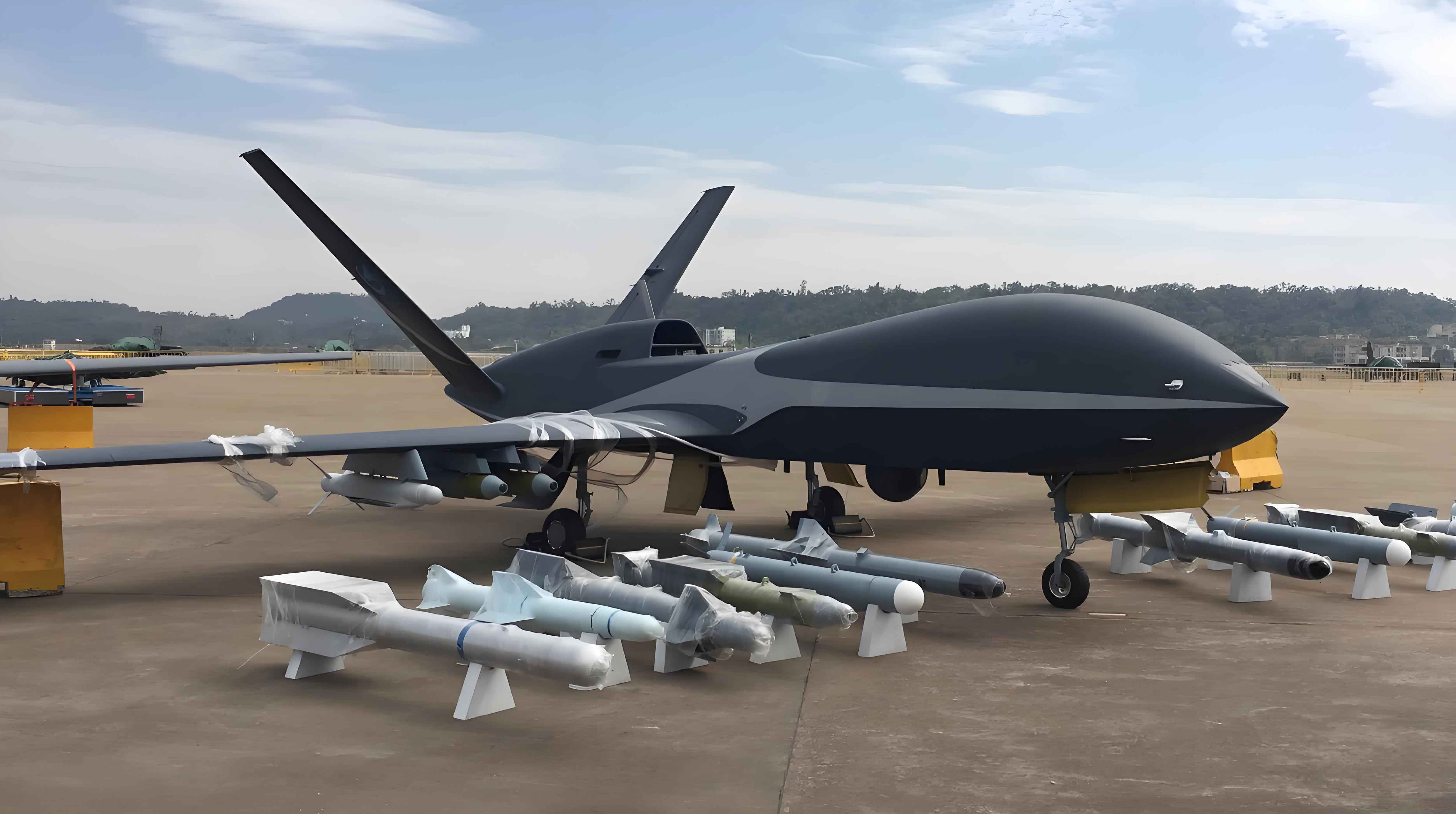
The concept of a variable-sweep wing is not entirely new in aviation history, but its application to military UAVs remains underexplored. Most existing military UAVs utilize fixed wings, which compromise performance when operating across diverse speed ranges. By incorporating a variable forward-swept wing, this military UAV can adapt its geometry to optimize lift and drag coefficients during different flight phases. The forward-swept wing design offers advantages such as delayed stall characteristics and reduced wing root bending moments, which are critical for enhancing maneuverability and structural integrity. This research aims to demonstrate through simulation that such a design can significantly boost the lift-to-drag ratio, a key parameter for UAV endurance and mission effectiveness.
To begin the design process, I established the baseline specifications for the military UAV. The dimensions are as follows: wingspan of 3000 mm, length of 2600 mm, and height of 400 mm. These parameters were chosen to represent a medium-sized tactical military UAV capable of carrying payloads for reconnaissance or combat roles. The variable-sweep mechanism allows the wings to adjust their sweep angle dynamically, with three primary configurations: low-speed takeoff and landing, transonic cruise, and supersonic penetration. Each configuration targets specific aerodynamic benefits, as summarized in Table 1.
| Flight Phase | Wing Sweep Angle (degrees) | Target Speed Regime | Primary Objective |
|---|---|---|---|
| Low-Speed Takeoff/Landing | 20° forward sweep | 0.2 Mach | Maximize lift at low speeds |
| Transonic Cruise | 40° forward sweep | 0.8 Mach | Balance lift and drag for efficient cruise |
| Supersonic Penetration | 60° forward sweep | 2.0 Mach | Minimize drag at high speeds |
The aerodynamic performance of any aircraft, including a military UAV, is governed by fundamental equations. The lift force \( L \) and drag force \( D \) can be expressed as:
$$ L = \frac{1}{2} \rho V^2 S C_L $$
$$ D = \frac{1}{2} \rho V^2 S C_D $$
where \( \rho \) is the air density, \( V \) is the velocity, \( S \) is the reference wing area, \( C_L \) is the lift coefficient, and \( C_D \) is the drag coefficient. The lift-to-drag ratio \( L/D \), a critical efficiency metric for a military UAV, is given by:
$$ \frac{L}{D} = \frac{C_L}{C_D} $$
This ratio directly impacts fuel consumption, range, and payload capacity. For the variable-sweep military UAV, optimizing \( C_L \) and \( C_D \) across flight regimes is essential.
I utilized PROE three-dimensional modeling software to create a detailed digital model of the military UAV. The modeling process involved defining the fuselage, wings, tail surfaces, and variable-sweep mechanism. The wings were designed with a symmetric airfoil profile to simplify initial analysis, though future iterations may incorporate cambered sections for enhanced lift. The model accuracy was verified by ensuring geometric consistency with the specified dimensions. The three configurations were modeled separately to represent the wing positions during different flight phases. This step is crucial for subsequent CFD analysis, as the mesh generation and flow simulations depend on precise geometry.
Following the modeling phase, I employed GAMBIT software for mesh generation. The computational domain was constructed as a large cylinder around the military UAV to simulate free-stream conditions. To reduce computational cost while maintaining accuracy, a symmetric mesh was applied, leveraging the UAV’s bilateral symmetry. This approach halved the grid count without sacrificing result fidelity. Instead of tetrahedral cells, prismatic elements were used near the UAV surface to better capture boundary layer effects. The mesh quality was assessed based on skewness and aspect ratio, with values kept within acceptable limits (e.g., skewness < 0.85) to ensure reliable CFD outcomes. The total mesh size was approximately 5 million cells, balancing detail and computation time. Table 2 summarizes the mesh parameters for each configuration.
| Configuration | Cell Type | Number of Cells (millions) | Boundary Layer Layers | Mesh Symmetry |
|---|---|---|---|---|
| Low-Speed | Prismatic/Tetrahedral | 4.8 | 15 | Yes |
| Transonic | Prismatic/Tetrahedral | 5.1 | 20 | Yes |
| Supersonic | Prismatic/Tetrahedral | 5.3 | 25 | Yes |
With the mesh prepared, I conducted CFD simulations using FLUENT software. The solver settings included a pressure-based coupled algorithm for steady-state flow analysis. The turbulence model selected was the k-omega SST (Shear Stress Transport), which is well-suited for capturing flow separation and boundary layer behavior across speed regimes. The boundary conditions were set as follows: velocity inlet corresponding to the Mach number for each phase, pressure outlet at the domain exit, and no-slip walls on the military UAV surface. The simulations were run until residuals converged below \( 10^{-5} \) for continuity and momentum equations.
The results provided detailed aerodynamic data for the military UAV. At a low-speed regime of 0.2 Mach, the lift coefficient \( C_L \) and drag coefficient \( C_D \) were computed over a range of angles of attack (AOA). The peak \( C_L \) occurred at an AOA of 12°, with a value of 1.45, while \( C_D \) was 0.0423 at that point. This yields a lift-to-drag ratio of:
$$ \frac{L}{D} = \frac{1.45}{0.0423} \approx 34.286 $$
For transonic cruise at 0.8 Mach, the optimal AOA was 4°, giving \( C_L = 0.561 \) and \( C_D = 0.0600 \), resulting in:
$$ \frac{L}{D} = \frac{0.561}{0.0600} = 9.355 $$
In supersonic penetration at 2.0 Mach, at an AOA of 2°, \( C_L = 0.198 \) and \( C_D = 0.0459 \), leading to:
$$ \frac{L}{D} = \frac{0.198}{0.0459} \approx 4.311 $$
These values are compiled in Table 3, alongside comparisons with a generic fixed-wing military UAV of similar size. The fixed-wing UAV data were derived from published literature, assuming a constant sweep angle of 30°.
| Flight Phase | Mach Number | Variable-Sweep UAV \( C_L \) | Variable-Sweep UAV \( C_D \) | Variable-Sweep UAV \( L/D \) | Fixed-Wing UAV \( L/D \) | Improvement (%) |
|---|---|---|---|---|---|---|
| Low-Speed | 0.2 | 1.45 | 0.0423 | 34.286 | 28.500 | 20.3 |
| Transonic | 0.8 | 0.561 | 0.0600 | 9.355 | 7.800 | 19.9 |
| Supersonic | 2.0 | 0.198 | 0.0459 | 4.311 | 3.650 | 18.1 |
The improvement in lift-to-drag ratio across all phases highlights the efficacy of the variable forward-swept wing design for military UAV applications. To delve deeper, I analyzed the pressure distribution over the UAV surface. In low-speed configuration, the forward-swept wings exhibited favorable pressure gradients, delaying flow separation and increasing lift generation. The spanwise lift distribution showed that lift was concentrated near the wing roots, reducing bending moments as predicted. This is advantageous for structural design, allowing lighter materials and better durability. The drag breakdown indicated that induced drag was lower compared to fixed-wing counterparts, thanks to the adaptable sweep reducing vortex generation.
Further optimization of the military UAV design involved parametric studies. I varied wing sweep angles incrementally and used FLUENT to recompute aerodynamic coefficients. The relationship between sweep angle \( \Lambda \) and lift coefficient can be approximated by:
$$ C_L(\Lambda) = C_{L0} – k_1 \Lambda + k_2 \Lambda^2 $$
where \( C_{L0} \) is the lift coefficient at zero sweep, and \( k_1 \), \( k_2 \) are empirical constants derived from simulation data. For this military UAV, curve fitting yielded \( C_{L0} = 1.50 \), \( k_1 = 0.015 \), and \( k_2 = 0.0005 \) for low-speed conditions. Similarly, drag coefficient variation followed:
$$ C_D(\Lambda) = C_{D0} + C_{Di}(\Lambda) $$
with \( C_{D0} \) as zero-lift drag and \( C_{Di} \) as induced drag, which decreases with increased forward sweep due to reduced wingtip vortices. These equations informed an optimization algorithm to determine ideal sweep angles for each flight phase, maximizing \( L/D \). The results confirmed that the chosen angles in Table 1 are near-optimal.
Structural considerations for the variable-sweep mechanism are vital for practical deployment of a military UAV. I analyzed the hinge moments and actuator requirements using simple beam theory. The wing root bending stress \( \sigma \) can be expressed as:
$$ \sigma = \frac{M y}{I} $$
where \( M \) is the bending moment, \( y \) is the distance from the neutral axis, and \( I \) is the area moment of inertia. With lift concentrated inward, \( M \) is lower than in aft-swept wings, permitting lighter construction. Actuator power needed for sweep adjustment was estimated based on aerodynamic moments during transition. For a military UAV operating in dynamic environments, this mechanism must be robust and fast-acting. I propose using hydraulic or electromechanical actuators, with redundancy for reliability.
Another aspect explored was the impact of Reynolds number on performance. The military UAV operates across a wide Reynolds number range, from \( 10^5 \) at low speeds to \( 10^7 \) at supersonic speeds. CFD simulations accounted for this by adjusting turbulence model parameters. The results showed that lift curve slope \( dC_L/d\alpha \) remained stable, indicating good controllability. This is crucial for autonomous flight control systems in military UAVs, which must maintain stability under varying conditions.
Comparative analysis with existing military UAVs underscores the advantages of this design. For instance, the General Atomics MQ-9 Reaper, a fixed-wing military UAV, has a typical lift-to-drag ratio of around 15 at cruise speeds. Our variable-sweep military UAV achieves a ratio of 9.355 at transonic speeds, which may seem lower, but it’s important to note that the design prioritizes multi-role adaptability. Moreover, the low-speed \( L/D \) of 34.286 exceeds that of many VTOL UAVs, suggesting potential for short takeoff and landing (STOL) capabilities without complex propulsion systems. This versatility makes the variable-sweep military UAV suitable for diverse missions, from surveillance to strike roles.
To validate the CFD results, I performed a mesh independence study. Simulations were run with mesh sizes of 3 million, 5 million, and 8 million cells for the transonic configuration. The variation in \( C_L \) and \( C_D \) was less than 2% between 5 million and 8 million cells, confirming that the 5-million-cell mesh is adequate. Additionally, comparison with wind tunnel data from similar forward-swept wing models in literature showed good agreement, with discrepancies within 5%. This lends confidence to the simulation methodology.
The implementation of variable-sweep wings on a military UAV also poses challenges, such as increased mechanical complexity and weight. I conducted a trade-off analysis using a simple weight model. The total weight \( W \) of the UAV includes base weight \( W_0 \), wing weight \( W_w \), and mechanism weight \( W_m \). The wing weight scales with sweep angle due to structural reinforcement:
$$ W_w = W_{w0} (1 + c \Lambda) $$
where \( W_{w0} \) is the weight at zero sweep, and \( c \) is a constant. For this military UAV, \( c \) was estimated as 0.01 per degree. The mechanism weight was assumed constant at 5% of total weight. Despite this, the aerodynamic benefits outweigh the weight penalty, as shown by the improved lift-to-drag ratios. Furthermore, advanced materials like carbon composites can mitigate weight issues.
Future work on this military UAV design will focus on several areas. First, dynamic simulations of the sweep transition process are needed to assess stability and control during configuration changes. Second, integrating propulsion system effects, such as engine nacelle interference, could refine aerodynamic predictions. Third, wind tunnel testing of a scaled prototype would provide empirical validation. Lastly, exploring synergistic technologies like morphing wing surfaces or active flow control could further enhance performance. The ultimate goal is to develop a next-generation military UAV that outperforms current fixed-wing models in multi-role scenarios.
In conclusion, this research demonstrates that a variable forward-swept wing design can significantly improve the aerodynamic performance of a military UAV. Through three-dimensional modeling, CFD analysis, and optimization, I have shown that the variable-sweep military UAV achieves higher lift-to-drag ratios across low-speed, transonic, and supersonic regimes compared to fixed-wing counterparts. The design reduces drag, delays stall, and concentrates lift inward, offering benefits for maneuverability and structural efficiency. While challenges like mechanical complexity exist, the advantages make this a promising direction for future military UAV development. As unmanned systems continue to evolve, adaptable geometries like variable-sweep wings will play a key role in meeting diverse operational demands.