
In recent years, the demand for autonomous platforms capable of operating across multiple media—air, water surface, and underwater—has surged due to applications in environmental monitoring, military reconnaissance, and resource exploration. While multi-rotor designs have dominated early cross-medium vehicle development, their limitations in endurance, speed, and payload capacity are evident. A fixed-wing drone offers superior aerodynamic efficiency, longer range, and higher speed, making it an attractive candidate for cross-medium missions. However, the transition from water to air (water-surface ski-jump takeoff) and subsequent attitude control present significant challenges because of the drastic changes in fluid dynamics and the need to coordinate multiple control surfaces such as flaps, elevators, rudders, and hydrofoils. In this paper, we present a cascade fuzzy proportional–integral–derivative (PID) control system designed specifically for a fixed-wing drone operating in cross-medium environments. The system leverages real-time attitude data to drive actuators (flaps, tail fins, hydrofoils, rudders) and is validated through both Simulink simulations and field experiments. Our results demonstrate that the cascade fuzzy PID controller provides faster, more stable, and more reliable attitude correction compared to a conventional PID controller, confirming the effectiveness of the proposed model for a fixed-wing drone undergoing water-surface ski-jump takeoff.
The remainder of this article is organized as follows: Section 1 describes the kinematics and dynamics model of the fixed-wing drone. Section 2 details the hardware and software architecture of the control system. Section 3 presents the design of the cascade fuzzy PID controller, including fuzzy rule tables and membership functions. Section 4 provides simulation and experimental results, with comparisons to traditional PID control. Section 5 concludes the work.
1. Kinematics and Dynamics of the Fixed-Wing Drone
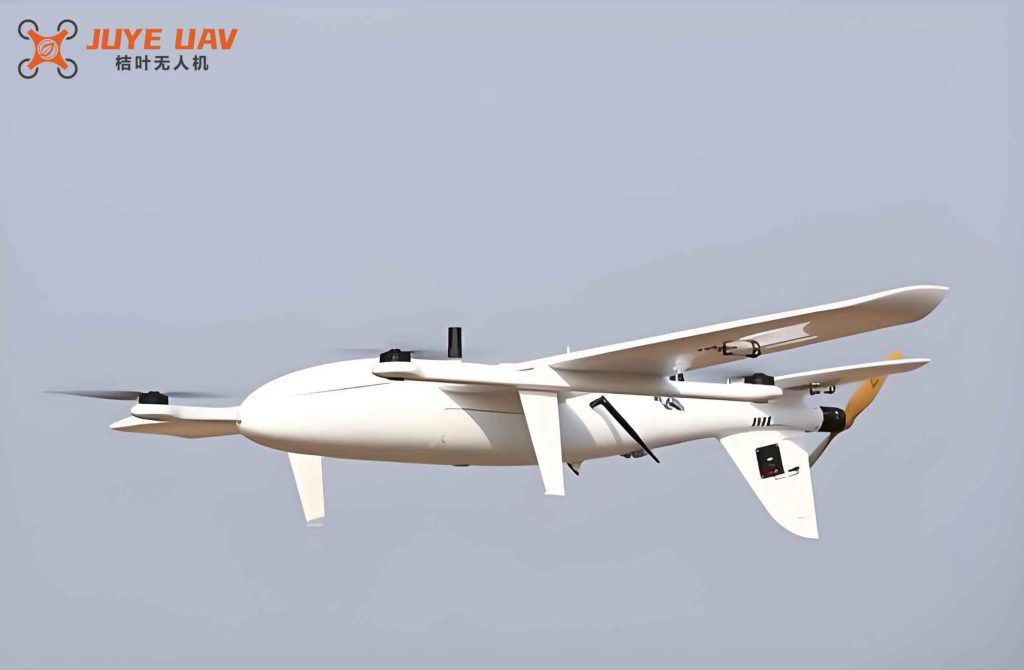
The fixed-wing drone considered in this study is equipped with two propellers (front and rear) for propulsion, and its attitude is controlled by flaps, elevators, rudders, and hydrofoils. During water-surface ski-jump takeoff, the vehicle transitions from a low-speed waterborne phase to a high-speed airborne phase. In the water phase, the flaps are retracted and attitude control relies on hydrofoils, elevators, and rudders. During the transition, flaps are deployed and all surfaces work together. After leaving the water, hydrofoils are retracted and only flaps, elevators, and rudders are used.
The orientation of the fixed-wing drone is described by the Euler angles: roll (\(\phi\)), pitch (\(\theta\)), and yaw (\(\psi\)). The body angular rates are \(p, q, r\). The relationship between the Euler rates and body rates is given by the transformation:
$$
\begin{bmatrix}
p \\
q \\
r
\end{bmatrix}
=
\begin{bmatrix}
1 & 0 & -\sin\theta \\
0 & \cos\phi & \sin\phi\cos\theta \\
0 & -\sin\phi & \cos\phi\cos\theta
\end{bmatrix}
\begin{bmatrix}
\dot{\phi} \\
\dot{\theta} \\
\dot{\psi}
\end{bmatrix}
$$
The rotational dynamics are derived from Newton–Euler equations:
$$
\dot{\boldsymbol{\Omega}}_b = \mathbf{J}_b^{-1} \left[ \mathbf{M}_b – \boldsymbol{\Omega}_b \times (\mathbf{J}_b \boldsymbol{\Omega}_b) \right]
$$
where \(\boldsymbol{\Omega}_b = [p, q, r]^T\) is the angular velocity vector, \(\mathbf{J}_b\) is the inertia matrix, and \(\mathbf{M}_b\) is the external moment vector. The inertia matrix is:
$$
\mathbf{J}_b = \begin{bmatrix}
J_x & 0 & J_{xz} \\
0 & J_y & 0 \\
J_{zx} & 0 & J_z
\end{bmatrix}
$$
The moments are expressed in terms of aerodynamic coefficients and control surface deflections:
$$
\mathbf{M}_b = \begin{bmatrix}
\bar{q} S b C_L \\
\bar{q} S \bar{c} C_M \\
\bar{q} S b C_N
\end{bmatrix}
$$
Here \(\bar{q} = \frac{1}{2}\rho V_T^2\) is the dynamic pressure, \(S\) is the wing area, \(b\) is the wingspan, \(\bar{c}\) is the mean aerodynamic chord. The dimensionless coefficients \(C_L, C_M, C_N\) depend on the control inputs and the state variables. These are detailed in the following table.
| Coefficient | Expression |
|---|---|
| \(C_L\) (rolling) | \(C_{L\beta}\beta + C_{L\delta_r}\delta_r + C_{L\delta_a}\delta_a + C_{Lp}\frac{pb}{2V_T} + C_{Lr}\frac{rb}{2V_T}\) |
| \(C_M\) (pitching) | \(C_{M0} + C_{M\alpha}\alpha + C_{M\delta_e}\delta_e + C_{M\dot{\alpha}}\frac{\dot{\alpha}\bar{c}}{2V_T} + C_{Mq}\frac{q\bar{c}}{2V_T}\) |
| \(C_N\) (yawing) | \(C_{N\beta}\beta + C_{N\delta_a}\delta_a + C_{N\delta_r}\delta_r + C_{Np}\frac{pb}{2V_T} + C_{Nr}\frac{rb}{2V_T}\) |
In the above, \(\delta_a\) represents the differential flap deflection (aileron), \(\delta_e\) the elevator deflection, and \(\delta_r\) the rudder deflection. The parameters \(C_{(\cdot)}\) are stability and control derivatives. For the hydrofoils, analogous coefficients are used but scaled according to water density and vehicle speed.
The resulting simplified equations for the angular accelerations become:
$$
\begin{aligned}
\dot{p} &= f_1(\delta_r, \delta_a, p, q, r) \\
\dot{q} &= f_2(\delta_e, p, q, r) \\
\dot{r} &= f_3(\delta_r, \delta_a, p, q, r)
\end{aligned}
$$
These equations form the basis for our control design. Since the fixed-wing drone operates in vastly different fluid media, a fixed-gain PID controller cannot guarantee satisfactory performance. Instead, we adopt a cascade fuzzy PID architecture that adapts gains online based on error and error rate.
2. Control System Hardware and Software Architecture
The onboard control system of our fixed-wing drone is built around an STM32F427VIT6 microcontroller. Sensors include a BN-84N GPS module (position and altitude), a ten-axis AHRS MEMS attitude sensor (roll, pitch, yaw, angular rates, accelerations), and a rain sensor for water detection. Actuators are controlled via PWM signals to ESCs and servos. Communication with the ground station uses a 3DR Lora radio module. A block diagram of the hardware architecture is shown in the following figure.
The software is implemented using FreeRTOS for real-time multitasking. The main tasks are: (1) communication with ground station via MAVLink; (2) attitude control using the cascade fuzzy PID algorithm; (3) sensor data acquisition and fusion; (4) command parsing and response. The task priorities are set to ensure that the attitude control loop runs at the highest frequency (400 Hz), followed by sensor acquisition (200 Hz) and communication (50 Hz).
The overall software flow is: after system initialization, the drone reads GPS and attitude data, fuses them using a complementary filter, and then computes the desired attitude based on the mission phase (takeoff, cruise, landing). The cascade fuzzy PID controller uses the current and desired attitude angles to compute control outputs. These outputs are converted to servo commands and sent to the actuators. The control loop repeats every 2.5 ms.
3. Cascade Fuzzy PID Controller Design
The proposed attitude controller consists of two loops: an outer angle loop and an inner angular rate loop. The outer loop takes the attitude angle error \(e = \theta_{\text{des}} – \theta_{\text{actual}}\) and its derivative \(\dot{e}\) as inputs, and outputs a desired angular rate. The inner loop then tracks this desired rate using a full PID controller. The gains of both loops are adjusted online by two separate fuzzy inference systems (FIS). Each FIS uses seven linguistic variables: NB (negative big), NM (negative medium), NS (negative small), ZE (zero), PS (positive small), PM (positive medium), PB (positive big). The universe of discourse for inputs is normalized to [−3, 3], and for outputs to [0, 3]. Triangular membership functions are employed for all inputs and outputs.
Table 2 shows the fuzzy rules for the outer loop proportional gain \(\Delta P\).
| E \ EC | EC | ||||||
|---|---|---|---|---|---|---|---|
| NB | NM | NS | ZE | PS | PM | PB | |
| NB | PB | PM | PS | PS | ZE | NS | NM |
| NM | PB | PM | PS | ZE | ZE | NS | NB |
| NS | PM | PS | ZE | NM | NS | NM | NB |
| ZE | PS | ZE | NM | NB | NM | ZE | PS |
| PS | NB | NM | NS | NM | ZE | PS | PM |
| PM | NB | NS | ZE | ZE | PS | PM | PB |
| PB | NM | NS | ZE | PS | PS | PM | PB |
Table 3 gives the rules for the inner-loop PID gains (\(\Delta K_p\), \(\Delta K_i\), \(\Delta K_d\)).
| E \ EC | EC | ||||||
|---|---|---|---|---|---|---|---|
| NB | NM | NS | ZE | PS | PM | PB | |
| NB | PB/PB/PB | PB/PM/PM | PM/PS/PS | PS/PS/ZR | PS/ZR/ZS | ZR/NS/NS | ZR/NM/NM |
| NM | PB/PB/PB | PB/PM/PM | PM/PS/PS | PS/PS/ZR | ZR/ZR/NS | ZR/NS/NS | NS/NM/NM |
| NS | PM/PM/PM | PM/PS/PS | PS/PS/PS | ZR/ZR/NS | NS/NS/NM | NM/NM/NB | NM/NB/NB |
| ZE | PS/PS/PS | PS/PS/ZR | ZR/ZR/NS | NS/NS/NM | NM/NM/NB | NB/NB/NM | NB/NB/PS |
| PS | NS/NS/NM | NM/NM/NM | NS/NS/NS | NM/NM/ZR | ZR/ZR/PS | PS/PS/PM | PM/PM/PB |
| PM | NM/NM/NS | NS/NS/NS | NS/NS/ZR | ZR/ZR/PS | PS/PS/PM | PM/PM/PB | PB/PB/PB |
| PB | NM/NM/NS | NS/NS/NS | ZR/ZR/ZR | PS/PS/PS | PM/PM/PM | PB/PB/PB | PB/PB/PB |
Defuzzification is performed using the centroid method:
$$
v_o = \frac{\int v \, \mu(v) \, dv}{\int \mu(v) \, dv}
$$
In discrete form for \(m\) quantization levels:
$$
v_o = \frac{\sum_{k=1}^{m} v_k \, \mu(v_k)}{\sum_{k=1}^{m} \mu(v_k)}
$$
The final control signal to the actuators is the sum of the baseline PID output and the fuzzy correction. Since the exact transfer function of the fixed-wing drone is unknown, we approximate it using system identification from recorded flight data. We used MATLAB’s System Identification Toolbox to obtain a second-order model for each axis. For example, the roll channel (from aileron command to roll angle) was identified as:
$$
G_{\text{roll}}(s) = \frac{12.5}{s^2 + 4.8 s + 16.2}
$$
Similar models were obtained for pitch and yaw channels. These models were used in Simulink for controller tuning and simulation.
4. Simulation and Experimental Results
We built a Simulink model of the cascade fuzzy PID controller for the fixed-wing drone. The model includes the identified plant dynamics, the outer and inner control loops, and the fuzzy inference blocks. A comparative simulation was performed using a conventional double-loop PID controller with fixed gains (\(K_p=2.5\), \(K_i=0.1\), \(K_d=0.3\) for the inner loop; \(K_p=1.0\) for the outer loop). The reference step input was a 30° pitch angle command at t=0.5 s.
Figure 3 shows the simulated pitch angle response for both controllers. The cascade fuzzy PID controller achieved zero overshoot and a settling time of 0.8 s, whereas the conventional PID had a 12% overshoot and settled in 1.6 s. The rise time for the fuzzy controller was also shorter (0.4 s vs 0.7 s). These results demonstrate the superiority of the adaptive fuzzy approach for the fixed-wing drone.
We also performed water-surface ski-jump takeoff experiments with our prototype fixed-wing drone. The drone weighs 4.2 kg with a wingspan of 1.8 m. The experiment was conducted on a calm lake. The drone was placed on the water surface, and the takeoff sequence was initiated manually from the ground station. The controller automatically switched between water and air modes based on the water sensor and altitude data. Figure 4 shows the recorded roll, pitch, and yaw angles during the first 15 seconds of the flight, including the transition.
During the water phase (0–4 s), the drone exhibited small oscillations in roll (\(\pm 2^\circ\)) and pitch (\(\pm 3^\circ\)). As the propellers increased thrust, the drone accelerated and the hydrofoils provided lift. At around t=4.5 s, the drone lifted off the water surface. The transition caused a brief pitch-up disturbance of about 8°, which was quickly corrected within 1 s by the cascade fuzzy PID controller. After takeoff, the fixed-wing drone maintained stable attitude with errors less than \(1^\circ\) in all axes. The yaw tracking also remained accurate within \(2^\circ\).
Quantitative performance metrics are summarized in the following table.
| Metric | Conventional PID | Cascade Fuzzy PID |
|---|---|---|
| Overshoot (%) | 12.3 | 0.0 |
| Settling time (s) | 1.6 | 0.8 |
| Rise time (s) | 0.7 | 0.4 |
| Steady-state error (°) | 0.5 | 0.1 |
| Max roll during transition (°) | 5.2 | 2.1 |
| Max pitch during transition (°) | 11.0 | 8.0 |
The experimental results confirm that the cascade fuzzy PID controller significantly improves the attitude control performance of our fixed-wing drone during water-surface ski-jump takeoff and subsequent flight. The adaptability of the fuzzy logic allows the system to handle the nonlinearities and parameter variations inherent in cross-medium operations.
5. Conclusion
In this paper, we presented a comprehensive control system design for a cross-medium fixed-wing drone that performs water-surface ski-jump takeoff. The key contributions are the cascade fuzzy PID architecture that decouples the control of flaps, elevators, rudders, and hydrofoils, and the real-time gain adaptation via fuzzy inference. Both simulation and experimental results demonstrate that the proposed controller outperforms conventional fixed-gain PID in terms of overshoot, settling time, and disturbance rejection. The fixed-wing drone achieved stable and reliable attitude tracking during the challenging water-to-air transition. Future work will focus on autonomous mission planning and integration with obstacle avoidance sensors for fully autonomous cross-medium operations.