
In response to the high-speed traversal scenario of the “UI-STRIVE” competition, we conducted research on visual navigation technology for fixed-wing drones. The competition requires a fixed-wing drone to sequentially cross two red gates placed on a route and return to the landing zone. The internal dimensions of each gate are 7 meters by 7 meters, with a border width of 0.8 meters. These gates are positioned on two platforms approximately 10 meters high and can move laterally within a range of [-14, +14] meters from their center positions. This task demands high-speed, accurate visual navigation to guide the fixed-wing drone through these gates as part of a dense formation flight. The core challenges include robust gate detection, precise pose estimation, and effective navigation strategies, especially given the high velocity of a fixed-wing drone compared to a rotary-wing counterpart.
The primary technical contributions of our work are threefold. First, we developed a robust gate detection algorithm based on color segmentation and cascaded filtering using the structural information of the gate. Second, we proposed an optimized pose estimation method that leverages the fixed-wing drone’s attitude prior to mitigate instability in long-distance scenarios. Third, we validated our approach through extensive real-flight tests and achieved the highest score in the competition. The following sections detail the coordinate system definitions, gate detection method, pose estimation algorithm, experimental setup, and results.
Coordinate System Definitions
To accurately describe the spatial relationships between the fixed-wing drone, camera, and target gate, we define four principal coordinate systems. The transformations between these systems are essential for our navigation algorithm.
We define the following coordinate systems:
- World Coordinate System $(O_0x_0y_0z_0)$: A global frame, often aligned with the North-East-Down (NED) convention. The origin is typically at the drone’s takeoff point.
- Body Coordinate System $(O_2x_2y_2z_2)$ : Fixed to the fixed-wing drone’s center of gravity. The $x_2$-axis points forward (nose), the $z_2$-axis points downward, and the $y_2$-axis completes the right-handed system.
- Camera Coordinate System $(O_3x_3y_3z_3)$: Originates at the camera’s optical center, mounted on the drone’s nose. Its axes are aligned with the image plane.
- Gate Coordinate System $(O_1x_1y_1z_1)$: Originates at the gate’s center. The $y_1$-axis is horizontal to the right, the $z_1$-axis is vertical downward, and the $x_1$-axis points forward along the crossing direction.
The transformation from a point $p_b$ in system $b$ to system $a$ is given by $p_a = R_{ab} \times p_b + t_{ab}$, where $t_{ab}$ is the origin of system $b$ expressed in system $a$, and $R_{ab}$ is the rotation matrix from $b$ to $a$. A summary of these coordinate systems and their roles is presented in Table 1.
| Coordinate System | Origin | Key Axes | Role in Navigation |
|---|---|---|---|
| World $(O_0x_0y_0z_0)$ | Takeoff point | North, East, Down | Global reference for the fixed-wing drone |
| Body $(O_2x_2y_2z_2)$ | Drone center of mass | Forward, Right, Down | Represents the fixed-wing drone’s orientation |
| Camera $(O_3x_3y_3z_3)$ | Camera optical center | Image horizontal, vertical, optical axis | Used for image-based gate detection |
| Gate $(O_1x_1y_1z_1)$ | Gate center | Forward, Right, Down | Target waypoint for the fixed-wing drone |
Gate Detection
Accurate detection of the gate’s corner points is the foundation of our visual navigation system. Our detection pipeline for the fixed-wing drone comprises three main components: HSV color segmentation, cascaded filtering based on the gate’s structural shape, and corner point detection from binary images.
HSV Color Segmentation
To ensure robustness against varying illumination, we first perform color segmentation in the HSV color space. Given the gate’s red color, we define a specific range in the HSV space. The segmentation is performed for H values in ranges [0°, 10°] and [160°, 180°], S in [100, 255], and V in [30, 255]. After obtaining the binary mask, we apply a morphological opening operation to remove noise. This step isolates potential gate regions from the complex background.
Cascaded Filtering Based on Gate Structure
The HSV-segmented image may contain false positives. To filter out non-gate regions, we designed a series of cascaded weak classifiers based on the gate’s known structure. The cascaded filtering process is as follows:
- Extract all contours from the segmented image and establish their hierarchical relationship (parent-child).
- Remove all isolated contours that have no parent or no child.
- Filter contours based on their aspect ratio, retaining only those with a ratio between 0.7 and 1.5.
- Remove contours based on area and the area ratio of parent to child contours. The area ratio must be between 1 and 2.
- Calculate the perimeter of a contour and its minimum bounding rectangle; remove contours where their ratio exceeds 1.3.
- Calculate the angle of the minimum bounding rectangle for parent-child pairs; remove pairs with an angle difference greater than 30°.
Finally, the contour pair with the largest area is selected as the gate’s outer and inner boundary. This cascade efficiently filters the image, retaining only the gate structure. Table 2 summarizes the filtering criteria used.
| Filter Stage | Criterion | Purpose |
|---|---|---|
| 1. Hierarchical Filter | Isolated contours (no parent or child) | Removes non-gate objects |
| 2. Shape Filter | Aspect ratio $\in [0.7, 1.5]$ | Removes overly elongated shapes |
| 3. Area Filter | Min area; parent/child area ratio $\in [1.0, 2.0]$ | Removes too small or disproportionally sized pairs |
| 4. Perimeter-Rectangle Filter | Perimeter ratio $\le 1.3$ | Ensures shape regularity |
| 5. Angle Filter | Angle difference of bounding rectangles $\le 30^\circ$ | Ensures structural alignment |
Corner Point Detection from Binary Image
After obtaining the binary image of the gate’s inner and outer boundaries, we extract line segments using the LSD (Line Segment Detector) algorithm on the local image regions corresponding to the gate. The line segments are then classified, and their intersections are computed to determine the corner points. The center points of the inner and outer gate boundaries are found by intersecting lines connecting opposite corners. To match the detected image corners to the actual gate corners without singularity when the fixed-wing drone’s roll angle is large, we use the drone’s roll angle to de-rotate the corner coordinates. This transformation ensures that the topological relationship (top-left, top-right, etc.) is consistent, allowing for correct matching.
UAV Pose Estimation
Using only angular information from the camera is insufficient for precise fixed-wing drone guidance, especially during maneuvers or in crosswind conditions. Therefore, we developed an optimized pose estimation algorithm that combines image data with the drone’s attitude priors to compute the relative pose between the fixed-wing drone and the gate.
Optimized Pose Solution
Using the 8 detected corner image points $q_i$ and their corresponding 3D coordinates $p_i$ in the gate coordinate system, we first solve the PnP problem using the EPnP algorithm. This provides an initial pose ($R_0$, $t_0$) of the gate relative to the camera. However, in our experiments, the position $t_{12}$ of the fixed-wing drone in the gate frame was highly unstable at distances greater than 150 meters. We identified that this instability was primarily due to inaccuracies in the rotation matrix $R_{31}$ from EPnP.
To mitigate this, we leverage the roll ($\alpha$) and pitch ($\beta$) angles from the fixed-wing drone’s flight controller, which are more reliable than the yaw angle. The core of our optimization is to correct the rotation matrix using these attitude priors. Let $R_{e31}$ be the rotation matrix from EPnP. The navigation system’s rotation to the gate frame is given by:
$$R_x(\alpha)R_y(\beta)R_z(\gamma) = R_{23}R_{e31}R_{10}$$
where $R_{23}$ is the camera-to-body rotation, $R_{10}$ is the gate-to-world rotation, and $\gamma$ is the yaw angle. We define $R_{e20} = R_{23}R_{e31}R_{10}$. Decomposing $R_{e20}$ into Euler angles yields:
$$\gamma_e = \arctan[R_{e20}(0,1), R_{e20}(0,0)]$$
We then use this corrected yaw $\gamma_e$, along with the original $\alpha$ and $\beta$ from the flight controller, to compute a more accurate rotation matrix:
$$R_{e31} = R_{23}^T R_x(\alpha) R_y(\beta) R_z(\gamma_e) R_{10}^T$$
Our final pose estimation algorithm proceeds as follows:
1. Solve the 3D-2D PnP problem using EPnP to get ($R_0$, $t_0$).
2. Apply the attitude correction to $R_0$ to obtain $R_1$.
3. Use ($R_1$, $t_0$) as an initial guess and perform iterative non-linear optimization using the g2o framework to refine the pose to ($R_2$, $t_2$).
4. Apply the attitude correction again to $R_2$ to get $R_3$.
5. Set the final camera-to-gate rotation and translation as $R_{31} = R_3$ and $t_{31} = t_2$.
6. Compute the final relative pose using the transformation equations.
This optimization process is summarized in Table 3.
| Step | Input | Operation | Output |
|---|---|---|---|
| 1 | Image corners $q_i$, 3D points $p_i$ | Initial EPnP solution | ($R_0$, $t_0$) |
| 2 | $R_0$, drone attitude ($\alpha$, $\beta$) | Attitude correction to compute $R_1$ | $R_1$ |
| 3 | ($R_1$, $t_0$) | Non-linear optimization (g2o) | ($R_2$, $t_2$) |
| 4 | $R_2$, drone attitude ($\alpha$, $\beta$) | Second attitude correction to compute $R_3$ | $R_3$ |
| 5 | $R_3$, $t_2$ | Set final pose: $R_{31}=R_3$, $t_{31}=t_2$ | Pose in camera frame |
Consistency Check and Gaussian Filtering
To eliminate high-frequency noise and outliers from the pose estimates, we apply a Gaussian-weighted filter to the results from the last $N$ frames. The weights are calculated as:
$$g_k = \exp\left(-\frac{1}{2}\left(\frac{k}{\sigma}\right)^2\right), \quad c_k = \frac{g_k}{\sum_{i=0}^{N-1} g_i}$$
where $k$ is the frame distance from the current frame, $N=10$, and $\sigma=3.0$. Additionally, we perform a consistency check. If the difference between the current estimate $x_k$ and the previous filtered estimate $x^{g}_{k-1}$ exceeds a threshold $\xi=5$, the current estimate is considered an outlier and replaced with $x^{g}_{k-1}$. This check is only applied when the fixed-wing drone is within 150 meters of the gate.
Experimental Design and Results
UAV System Design
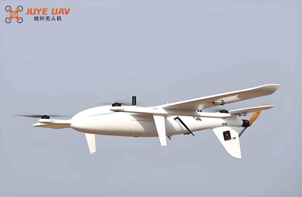
To validate our visual navigation technology, we designed a fixed-wing drone system as shown in the image below. The fixed-wing drone has a twin-propeller power system, a wingspan of 1.4 meters, and a total mass of approximately 6.9 kg. It is equipped with an OSG230-150UC industrial camera and a 12 mm HF-10MP lens for image acquisition, providing a resolution of 1920×1200 pixels with a horizontal and vertical field of view of 40.2° and 30.6°, respectively. An INTEL NUC8i7BEH onboard computer processes the images, and a Pixhawk4 flight controller manages the fixed-wing drone’s flight. The camera is mounted on the drone’s nose to avoid obstructions.
Analysis of Flight Test Results
We compared the pose estimation results from four methods: basic EPnP, our proposed optimized method, EPnP with Gaussian filtering, and our optimized method with Gaussian filtering. The results are summarized in Table 4.
| Method | Long-Distance Stability | Convergence to Gate Center | Noise Suppression |
|---|---|---|---|
| Basic EPnP | Poor (large oscillations in $t_{12}$) | Inconsistent | None |
| Optimized EPnP (ours) | Good (suppressed oscillations) | Improved | Improved |
| EPnP + Gaussian Filter | Moderate | Improved, but initial oscillations remain | Good |
| Optimized + Gaussian Filter (ours) | Excellent (smooth, stable) | Consistent and smooth | Excellent |
The results clearly demonstrate that our optimized pose estimation method, combined with the attitude prior from the fixed-wing drone’s flight controller, significantly improves the stability of the estimated position ($x_2, y_2, z_2$) at long distances. The Gaussian filtering further smooths the output, particularly for the lateral ($y_2$) and vertical ($z_2$) components in the gate frame. As the fixed-wing drone approaches the gate, the filtered navigation parameters converge smoothly towards the gate center (0,0,0), providing a reliable guidance signal.
In the second “UI-STRIVE” high-speed crossing competition, our visual navigation technology was instrumental in guiding the fixed-wing drone through all gates successfully. The cascaded filter ensured robust gate detection in various lighting conditions, and the optimized pose estimation provided the precise relative positioning required for high-speed, dense formation flight. Our fixed-wing drone team achieved a final score of 11.14 points, the highest in the competition. This outcome validates the feasibility and advanced nature of our proposed visual navigation technology for high-speed fixed-wing drone operations.
Conclusion
We have presented a complete visual navigation system for a fixed-wing drone performing high-speed gate crossing. Our approach combines robust gate detection through HSV segmentation and cascaded filtering with an optimized pose estimation algorithm that leverages the drone’s attitude priors. The experimental results from real flight tests and the “UI-STRIVE” competition confirm the system’s ability to provide stable and accurate navigation guidance, enabling the fixed-wing drone to successfully complete complex traversal tasks. This work provides an effective solution for similar high-speed visual navigation challenges involving a fixed-wing drone.