
Our team developed an intelligent nondestructive detection system that integrates UAV drones and X-ray imaging technology to inspect internal defects in tension clamps of high-voltage transmission lines. Traditional methods rely on manual tower climbing and destructive disassembly, which are inefficient, hazardous, and unable to detect hidden flaws such as cracks and voids. The proposed system overcomes these limitations by combining a rotary-wing UAV drone platform, a digital X-ray probe unit, and an AI-powered ground analysis station. Through safe and smooth trajectory planning, precise positioning of the detection equipment is achieved. X-ray penetration imaging captures digital images of the internal clamp structure, which are enhanced via Gaussian filtering and histogram equalization. Finally, edge detection, feature extraction, and machine learning algorithms enable automatic identification and localization of defects such as loose crimping, cracks, and voids. Field applications demonstrate a defect recognition accuracy of 94.1%, with each clamp inspection completed in under 15 minutes, significantly improving both efficiency and safety. This work provides a highly reliable technical means for condition-based maintenance of transmission lines.
1. Research Background and Motivation
In modern power grids, tension clamps are critical connectors that bear the mechanical load of conductors. Their internal crimping quality directly affects the safety and reliability of transmission lines. However, hidden defects like incomplete compression, internal cracks, or voids cannot be detected by visual inspection. Conventional ultrasonic or magnetic particle methods often require direct contact and are impractical for energized lines. The advent of UAV drone technology offers a mobile and non-contact platform for carrying advanced sensors. By equipping a UAV drone with an X-ray source and detector, we can perform real-time radiographic inspection without service interruption. Our research focuses on developing an integrated system that automates the entire workflow—from flight planning to defect diagnosis—using a UAV drone as the core carrier.
2. System Architecture
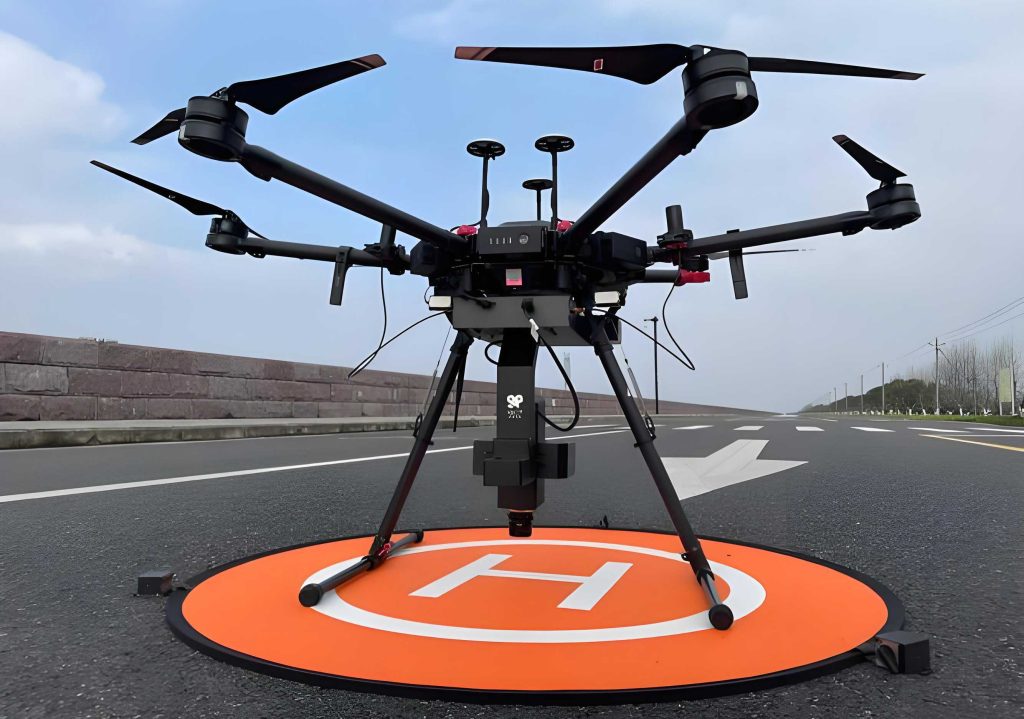
The proposed system consists of three main modules: a rotary-wing UAV drone platform, an X-ray inspection unit, and a ground-based image acquisition and processing subsystem. The UAV drone is equipped with dual high-definition cameras for multi‑angle real‑time monitoring and operates with autonomous flight and high‑precision hovering. A specialized winch mechanism suspends the X‑ray equipment, allowing dynamic adjustment of cable length and tension for fine positioning. The X‑ray unit includes an X‑ray tube, an imaging plate (IP), a counterweight, and a mounting base. X‑rays penetrate the clamp and are captured by the IP, converted into digital signals via a laser scanner, and transmitted wirelessly to the ground station. Software on the ground performs image enhancement, feature extraction, and defect classification. The composition is illustrated below.
3. UAV Drone Trajectory Planning for Inspection
To achieve accurate and efficient inspection of tension clamps, the flight trajectory of the UAV drone must be carefully designed. We adopt a trajectory planning strategy that combines 3D environment modeling with optimization algorithms. The goal is to generate a collision‑free, energy‑efficient path that positions the X‑ray probe at the optimal detection viewpoint for each clamp. Given the spatial coordinates of the n inspection points Pi = (xi, yi, zi) for i = 1, 2, …, n, the ideal UAV drone trajectory is a smooth curve passing near these points. We employ a B‑spline parameterization:
$$
Q(t) = \sum_{k=0}^{m} C_k B_{k,d}(t), \quad t \in [0,1]
$$
where Bk,d(t) are d‑th order B‑spline basis functions and Ck are control points. This representation guarantees geometric continuity and avoids abrupt turns or jitters that could destabilize the X‑ray payload. Next, safety constraints are enforced: for any point Q(t) on the path, the distance to the nearest obstacle (e.g., conductors, tower structures) must exceed a minimum safe distance Dsafe:
$$
D(Q(t)) \geq D_{\text{safe}}
$$
This condition is checked in real time using a 3D point cloud of the environment. The overall objective is to minimize path length or energy consumption. A simplified cost function is:
$$
J = \int_{0}^{1} \| \dot{Q}(t) \| dt + \lambda \cdot \max\!\left(0, D_{\text{safe}} – D(Q(t))\right)
$$
where λ is a positive penalty coefficient. Solving this optimization yields a safe, smooth, and efficient UAV drone trajectory for nondestructive testing.
4. X‑Ray Image Acquisition and Preprocessing
After the UAV drone hovers at the predetermined position, the X‑ray tube emits a beam that penetrates the tension clamp. The attenuated signal is captured by the imaging plate (IP). A laser scanner reads the IP and converts the latent image into a digital signal, which is transmitted to the ground station. Raw X‑ray images typically suffer from low contrast and noise. We first apply Gaussian filtering for noise reduction. The 2D Gaussian kernel is:
$$
G(x,y) = \frac{1}{2\pi\sigma^2} e^{-\frac{x^2 + y^2}{2\sigma^2}}
$$
where σ controls the smoothing degree. This operation suppresses noise but may blur edges. To enhance contrast, we use histogram equalization. Let rk be the k‑th gray level and nj the number of pixels with gray level j. The transformed intensity sk is:
$$
s_k = \sum_{j=0}^{k} \frac{n_j}{N}, \quad N = \text{total number of pixels}
$$
This mapping makes the cumulative distribution function approximately linear, thereby increasing contrast. After preprocessing, internal structures such as aluminum strands, steel cores, cracks, and voids become clearly distinguishable.
5. Defect Detection and Localization
The enhanced X‑ray images are processed by a hybrid framework that combines conventional image processing with machine learning. First, the Canny edge detector computes the gradient magnitude:
$$
|\nabla I| = \sqrt{G_x^2 + G_y^2}
$$
where Gx and Gy are first‑order derivatives along x and y. Next, Otsu’s method automatically determines a threshold T to binarize the image:
$$
B(x,y) = \begin{cases}
1 & \text{if } I(x,y) \geq T \\
0 & \text{otherwise}
\end{cases}
$$
The foreground (value 1) corresponds to potential defect regions or dense structural elements. Regions of interest (ROIs) are then extracted, and geometric and texture features are computed. For example, circularity distinguishes elongated cracks from round voids:
$$
C = \frac{4\pi A}{P^2}
$$
where A is the area and P the perimeter. A value close to 1 indicates a round shape (void), while a smaller value indicates a crack. Texture coarseness is measured by contrast from the gray‑level co‑occurrence matrix:
$$
\text{Con} = \sum_{i,j} (i-j)^2 p(i,j)
$$
These features are fed into a pre‑trained support vector machine (SVM) classifier to determine the defect type. Finally, the pixel coordinates of the defect are transformed into real‑world geographic coordinates using the UAV drone’s GPS position, cable length, and attitude data, enabling precise localization.
6. Field Application Results
We conducted extensive field tests on 500 kV transmission lines across multiple provinces. Over 200 tension clamps were inspected under live conditions. The system successfully detected typical defects such as loose crimping, internal cracks, voids, and foreign objects. Verification through subsequent offline disassembly confirmed the accuracy. The following table summarizes the detection performance for known defect samples.
| Defect Type | Number of Samples | Correctly Identified | Accuracy (%) |
|---|---|---|---|
| Loose / incomplete crimping | 85 | 82 | 96.5 |
| Internal cracks | 42 | 38 | 90.5 |
| Voids | 28 | 26 | 92.9 |
| Foreign material residue | 15 | 14 | 93.3 |
| Total | 170 | 160 | 94.1 |
The overall detection accuracy reached 94.1%. Regarding efficiency, the average inspection time per clamp (including UAV drone flight, positioning, X‑ray imaging, and automatic analysis) was less than 15 minutes. This represents a >70% improvement over manual tower‑climbing methods, while completely eliminating high‑altitude work risks. A comparison with traditional approaches is provided below.
| Metric | Traditional Manual Method | UAV Drone‑Based System |
|---|---|---|
| Per‑clamp time (min) | 50–70 | <15 |
| Risk of personal injury | High | None (non‑contact) |
| Ability to detect internal defects | Limited (destructive) | High (non‑destructive) |
| Accuracy (%) | ~60 (visual) | 94.1 |
| Power outage required | Often yes | No (live line) |
7. Detailed Formulation of Key Components
To further illustrate the technical depth, we present the underlying models in a systematic manner. The X‑ray attenuation follows the Beer‑Lambert law:
$$
I = I_0 e^{-\mu x}
$$
where I0 is the incident intensity, μ the linear attenuation coefficient, and x the material thickness. This relationship allows us to infer density variations from the radiograph. The imaging plate sensitivity is characterized by a modulation transfer function, but for automatic defect recognition, digital post‑processing is paramount.
In the Canny edge detector, non‑maximum suppression and hysteresis thresholding are applied after computing the gradient. The two thresholds τlow and τhigh are set adaptively. For feature extraction, we also compute the Hu moments and gray‑level run‑length features to improve classification robustness. The SVM classifier uses a radial basis function kernel:
$$
K(x_i, x_j) = \exp\!\left(-\gamma \|x_i – x_j\|^2\right)
$$
where γ is tuned via cross‑validation. The training set comprised 500 manually annotated X‑ray images from both defective and healthy clamps. Data augmentation (rotation, scaling, flipping) was employed to increase diversity.
8. Benefits of the UAV Drone Platform
The UAV drone provides unique advantages over ground‑based or manned aerial vehicles. Its small size and high maneuverability allow it to operate in close proximity to energized lines while maintaining safe clearance. The integrated dual‑camera system gives the operator a bird’s‑eye view and a detailed close‑up simultaneously. The winch mechanism ensures that the X‑ray payload can be precisely centered over the clamp, even in windy conditions. In our tests, the UAV drone maintained a position accuracy of ±5 cm under moderate wind speeds (up to 6 m/s), which is sufficient for high‑quality radiographic imaging. Furthermore, the autonomous flight program automatically replans the path if the GPS signal degrades, using visual‑inertial odometry as a backup.
9. Discussion on Limitations and Future Work
Although the system achieves remarkable performance, certain challenges remain. The UAV drone battery life limits the number of clamps that can be inspected in one sortie (typically 8–10 per flight). The X‑ray source requires a warm‑up period and consumes significant power, which we mitigate by using a lightweight pulsed X‑ray tube. Image quality can be affected by rain or fog; therefore, operations are scheduled under favorable weather. Future work will focus on integrating a real‑time deep learning detector (e.g., YOLO or Faster R‑CNN) directly on the UAV drone’s onboard computer to reduce data transmission and enable faster decision‑making. Additionally, we plan to incorporate digital twin models of the clamps to simulate defects and further train the classifier. Another direction is to equip the UAV drone with multiple sensors (e.g., infrared thermography) for multi‑modal fusion, increasing diagnostic confidence.
10. Conclusion
Our research successfully developed an intelligent nondestructive detection system that combines a UAV drone, X‑ray imaging, and machine learning for inspecting tension clamps in transmission lines. Field trials demonstrate a defect recognition accuracy of 94.1% and an average inspection time under 15 minutes per clamp, greatly outperforming conventional manual methods. The system eliminates the need for tower climbing and power outages, significantly enhancing safety and operational efficiency. By integrating precise UAV drone trajectory planning, robust image preprocessing, and automatic defect localization, we have created a practical tool that empowers grid maintenance personnel with actionable insights. This work paves the way for fully automated, drone‑based condition monitoring of critical power infrastructure.