In recent years, the C-band, typically ranging from 4 to 8 GHz, has become a critical spectral resource due to its favorable propagation characteristics and substantial available bandwidth. It is extensively utilized in satellite communications, 5G mobile networks, aeronautical navigation, and meteorological radar systems. However, the intensive reuse of this spectrum has led to increasingly severe interference between different systems. Notable examples include out-of-band blocking interference from 5G base stations to C-band satellite earth stations and co-channel interference from microwave links to weather radars. Such interference poses a direct threat to the operational security of critical infrastructure.
Traditional methods for locating interference sources rely on fixed monitoring stations and vehicular-mounted equipment, typically following a “first regional localization, then ground-based逼近 search” approach. However, for C-band radio applications, this traditional paradigm faces significant challenges. Signals in this band experience high free-space path loss, are often transmitted with relatively low power and high directivity (as in satellite uplinks), and are highly susceptible to blockage by buildings and terrain. Ground-based monitoring is further hampered by severe multipath effects and non-line-of-sight (NLOS) propagation, which cause drastic signal attenuation and distortion of direction-of-arrival (DoA) information. It becomes exceedingly difficult to effectively capture weak sidelobe signals or achieve high-precision direction-finding, creating pronounced blind spots in densely built urban areas or regions with complex topography.
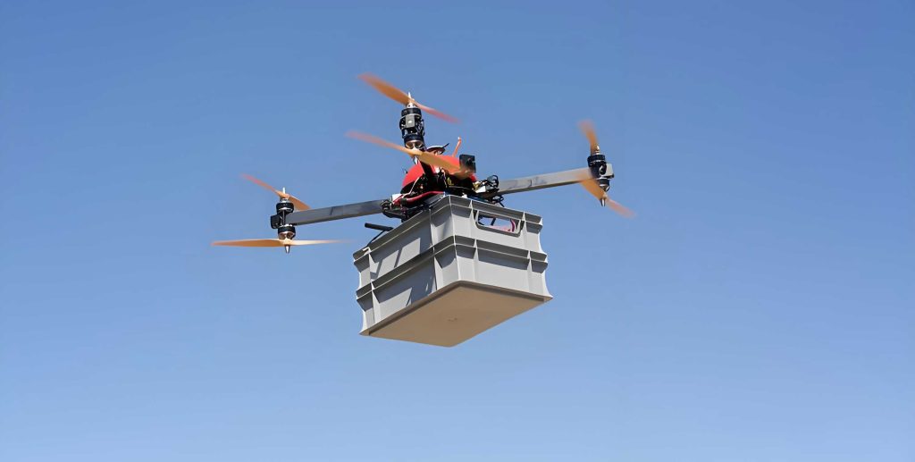
Lightweight UAV drones offer a transformative platform for radio monitoring, boasting advantages such as vertical take-off and landing, flexible deployment, and rapid response. By elevating the monitoring system to altitudes above 120 meters, UAV drones can effectively circumvent ground-level obstacles, establishing near free-space line-of-sight (LoS) propagation links. This capability significantly improves the reception conditions for high-frequency signals. Therefore, researching C-band interference source monitoring methods based on UAV drones is of paramount importance for enhancing the efficiency of radio spectrum management. This article systematically investigates the methodology for locating C-band interference sources using UAV drones, presents quantitative experimental analyses comparing UAV performance against traditional methods, and discusses the implications for practical radio regulation.
1. System Architecture and Experimental Philosophy
To quantify the advantages of a UAV-based radio monitoring system over traditional ground-based逼近 search techniques, a comprehensive field test was designed. The core objective was to validate the capability of a UAV drones system to locate C-band satellite interference sources. The experiment simulated transmissions from a C-band satellite system ground terminal. Under the performance constraints of the contemporary UAV drones monitoring system used, the test aimed to determine the maximum coverage distance for signals under various propagation environments and transmission states. A synchronized comparative test using traditional ground-based逼近 search methods was conducted in parallel.
The test selected two canonical propagation environments: a rural setting and an urban setting. The rural environment featured a transmission point located in open farmland, surrounded by low-rise buildings and vegetation, with flat terrain offering propagation conditions approximating free space. The urban environment positioned the transmitter on a rooftop approximately 30 meters above ground level, with the monitoring path traversing a dense area of buildings exceeding 10 stories, where multipath and blockage effects were dominant. The equipment utilized for the test is listed in Table 1.
| Subsystem | Equipment | Model | Frequency Range | Key Parameters |
|---|---|---|---|---|
| UAV Receiving End | UAV System | DZF-AC3 | 200 MHz – 8 GHz | Sensitivity: -107 dBm |
| Onboard Receiver | Integrated | 5 GHz – 7 GHz | Gain: Adjustable | |
| Ground Receiving End | Antenna | Jianwei Chuangye | 5 GHz – 7 GHz | Gain: 10 dBi |
| Low-Noise Amplifier (LNA) | Dongfang Botai | 5 GHz – 7 GHz | Gain: 40 dB | |
| Spectrum Analyzer | Keysight N9344C | 9 kHz – 20 GHz | Sensitivity: -144 dBm | |
| Transmission End | Signal Generator | R&S SMW200A | 100 kHz – 20 GHz | Modulation: Various PSK |
| Power Amplifier (PA) | Dongfang Botai | 1 GHz – 6 GHz | Gain: 1-50 dB | |
| Horn Antenna | Dongfang Botai | 5 GHz – 7 GHz | Gain: 20 dBi | |
| Accessories: Tripods, Cables, etc. | ||||
2. Theoretical Framework and UAV Monitoring Methodology
The fundamental advantage of UAV drones in radio monitoring stems from the establishment of an elevated LoS path. The received signal power \(P_r\) can be modeled as:
$$P_r = P_t + G_t + G_r – L_{total}$$
where \(P_t\) is the transmitted power, \(G_t\) is the transmitter antenna gain, \(G_r\) is the receiver antenna gain, and \(L_{total}\) is the total path loss. For ground-based monitoring, \(L_{total}\) is a complex sum of free-space path loss, diffraction loss, reflection loss, and scattering loss. UAV drones primarily aim to minimize the non-free-space components.
The free-space path loss (FSPL) is given by the Friis transmission equation:
$$L_{fspl} = 20\log_{10}(d) + 20\log_{10}(f) + 20\log_{10}\left(\frac{4\pi}{c}\right)$$
where \(d\) is the distance in meters, \(f\) is the frequency in Hz, and \(c\) is the speed of light. A more practical form in logarithmic scale is:
$$L_{fspl}\text{ (dB)} = 32.45 + 20\log_{10}(f_{\text{MHz}}) + 20\log_{10}(d_{\text{km}})$$
For our test frequency of \(f = 5900\) MHz, this simplifies to:
$$L_{fspl}\text{ (dB)} = 107.87 + 20\log_{10}(d_{\text{km}}) \quad \text{for } d \text{ in km}$$
The theoretical received power at the UAV drones or ground station, assuming free-space conditions, is then:
$$P_{r,theoretical}\text{ (dBm)} = EIRP + G_r – L_{fspl}$$
where \(EIRP = P_t + G_t\) is the Effective Isotropic Radiated Power. In our test, the transmitter EIRP was set to 40 dBm, and the receiving antenna gain on the UAV drones was approximately -5 dBi (due to its quasi-omnidirectional pattern for scanning).
The UAV drones monitoring methodology involves a systematic search pattern. The UAV drones is flown to a predetermined altitude and then navigates along a grid or spiral path, continuously measuring the received signal strength indicator (RSSI) and attempting DoA estimation using onboard systems. The key is that the UAV drones’ altitude \(h_{UAV}\) directly increases the radio horizon distance \(d_{horizon}\), calculated as:
$$d_{horizon} \approx \sqrt{2kR_e} \left( \sqrt{h_{tx}} + \sqrt{h_{rx}} \right)$$
where \(k\) is the effective Earth radius factor (typically 4/3 for standard radio propagation), \(R_e\) is the actual Earth radius, \(h_{tx}\) is the transmitter height, and \(h_{rx}\) is the receiver (UAV drones) height. By flying at 120 m, the UAV drones dramatically extends the potential LoS range compared to a ground vehicle at 2-3 m height, especially when searching for low-power, terrestrial-based C-band interference sources that may be intentionally or unintentionally hidden.
3. Experimental Setup and Variable Design
The test was designed to isolate and analyze the impact of several critical variables on monitoring performance. At each test point, the control variable method was applied, synchronously recording the received signal level on both the UAV drones platform and the ground-based equipment. This allowed for a direct comparison of signal-to-noise ratio (SNR) and coverage. The defined variables and their values are summarized in Table 2.
| Variable | Values | Rationale / Simulation Target |
|---|---|---|
| Transmitter Elevation Angle | 30°, 55°, 80° | Simulates different latitude-dependent satellite look angles for an earth station. |
| Transmitter Azimuth Angle | 0°, 55°, 180° | Corresponds to monitoring the main lobe, a sidelobe, and the back lobe of the transmitting antenna pattern. |
| UAV Drones Flight Altitude | 50 m, 120 m | Represents a lower operational bound and a higher, more effective altitude for urban clutter clearance. |
| Horizontal Distance from UAV to Source | 1 km to 7 km | Measures coverage capability as a function of range. |
| Propagation Environment | Rural, Urban | Provides contrast between near-free-space and severe multipath/clutter environments. |
The UAV drones platform was equipped with a calibrated receiver covering the C-band. The ground-based逼近 search used a high-gain directional antenna (10 dBi) paired with a 40 dB LNA, providing a significantly higher gain link than the UAV drones system for baseline comparison. This setup allowed us to discern whether the advantage of UAV drones was purely due to superior link budget or also due to improved spatial positioning overcoming propagation impairments.
4. Test Results and Quantitative Analysis
4.1 Monitoring Coverage Capability Analysis
The core performance metric is the maximum distance at which a usable signal (SNR > threshold) can be received. The theoretical free-space received power was calculated using the formula \(P_{r,theoretical} = 40 \text{ dBm (EIRP)} – 5 \text{ dB (G}_r) – L_{fspl}\). A comparison between theoretical values and maximum actual received levels at the UAV drones for both altitudes is presented in Table 3.
| Environment | Distance (km) | Free-Space Loss (dB) | Theoretical P_r (dBm) | Measured P_r at 120m UAV (dBm) | Measured P_r at 50m UAV (dBm) |
|---|---|---|---|---|---|
| Rural | 1.0 | 107.87 | -72.87 | -75.9 | -82.4 |
| 2.0 | 113.89 | -78.89 | -82.9 | -98.8 | |
| 3.0 | 117.41 | -82.41 | -92.9 | -98.1 | |
| 4.3 | 120.54 | -85.54 | -95.3 | No Signal | |
| 5.2 | 122.19 | -87.19 | -97.5 | -99.5 | |
| 7.0 | 124.77 | -89.77 | -102.3 | No Signal | |
| Urban | 1.1 | 108.69 | -73.69 | -91.0 | -98.9 |
| 1.8 | 112.97 | -77.97 | -84.4 | -97.8 | |
| 3.3 | 118.24 | -83.24 | -97.7 | No Signal | |
| 4.5 | 120.93 | -85.93 | -105.1 | No Signal |
The data reveals several critical insights. First, in the rural environment, the actual received levels at 120m UAV drones altitude are much closer to the theoretical free-space values than those at 50m. The 120m UAV drones maintained a stable link up to 7 km, while the 50m UAV drones lost signal intermittently beyond 4.3 km. Second, the urban environment presents a harsher reality. The additional loss due to clutter and multipath is evident, with received levels at 1.1 km being nearly 20 dB worse than theory. However, the 120m UAV drones still significantly outperformed the 50m UAV drones, extending the reliable detection range from under 1.8 km to 4.5 km.
The underlying mechanism is elucidated in Table 4. In urban settings, low-altitude monitoring is severely affected by localized blockage and destructive interference from reflections. Elevating the UAV drones to 120m allows it to “peek over” the majority of obstacles, establishing a more stable, direct LoS path or a single, dominant reflection path, thereby reducing fading and improving signal consistency. In rural areas, while the environment is generally open, low-altitude flight can still be affected by minor terrain features, tree lines, or ground reflections. The higher altitude of the UAV drones provides a cleaner, more consistent propagation path, enhancing long-range coverage and spatial signal homogeneity, which is crucial for accurate DoA estimation.
| Comparison Dimension | Urban Environment | Rural Environment | Comprehensive Conclusion |
|---|---|---|---|
| Signal Propagation Characteristics | Pronounced multipath effects, strong building blockage. | Approximates free-space propagation, minimal blockage. | Urban: complex reflections, rapid signal degradation. Rural: gradual attenuation, stable main lobe. |
| Low-Altitude (50m) Performance | Severely obstructed, high signal level fluctuation. | Minor local terrain influence, overall stable. | Urban low-altitude signals are significantly compromised; rural low-altitude remains usable but limited. |
| High-Altitude (120m) Performance | Markedly improved signal continuity, clearer main lobe identification. | Optimal line-of-sight, maintains stability at long range. | High altitude significantly improves signal quality and coverage in both environments. |
| Primary Benefit of Altitude Increase | Evades building blockage, reduces multipath interference. | Surmounts terrain obstacles, improves long-range reception. | The improvement mechanism differs (clutter vs. curvature), but the net gain is consistently positive. |
4.2 Comparative Analysis with Traditional Ground-Based Monitoring
The effectiveness of the traditional ground-based逼近 search was evaluated alongside the UAV drones tests. The ground system, with its 40 dB LNA, had a substantial link gain advantage over the UAV drones system. However, its performance was ultimately limited by the fundamental constraints of ground-level propagation. The maximum detection ranges for the three methods under the condition where SNR falls below a usable threshold (5 dB) are compared in Table 5.
| Test Environment | Maximum Detection Range (SNR > 5 dB) (km) | ||
|---|---|---|---|
| UAV at 120m | UAV at 50m | Ground-Based Search | |
| Rural Environment | 7.0 | 3.0 | 4.3 |
| Urban Environment | 4.5 | 1.8 | 2.3 |
The results are striking. Even with its superior receive gain, the ground-based method was outperformed by the 120m UAV drones in both environments. In the urban case, the UAV drones at 120m nearly doubled the detection range. The ground vehicle, despite its sensitive equipment, was often trapped in “urban canyons” where signals were either completely blocked or arrived via multiple reflected paths so scrambled that determining a true direction of arrival was virtually impossible. The UAV drones, by ascending above the clutter, recovered a viable signal and a more reliable DoA.
The practical operational differences are profound and are summarized in Table 6. Deploying UAV drones is logistically simpler in most areas outside strict airspace restrictions, requiring primarily a pre-flight checklist and local notification. Finding a suitable elevated ground point (hill, building roof) is often time-consuming, involves negotiations for access and power, and even then, the chosen point may not provide an optimal or unobstructed view. The agility of UAV drones to position the sensor at the optimal point in three-dimensional space on-demand is a decisive operational advantage for rapid response in interference hunting scenarios.
| Evaluation Criterion | UAV Drones-Based Monitoring System | Traditional Ground Vehicle | Fixed High-Ground-Point Monitoring |
|---|---|---|---|
| Site Accessibility & Setup | Easy. Outside controlled airspace, requires only site survey and flight notification. | Easy. Can operate from roads, parking lots. | Difficult. Requires identifying and securing access to suitable high points, often involving coordination and power negotiation. |
| Propagation Environment Control | Excellent. Can hover in open airspace, minimizing terrain/building impact. | Poor. Antenna is at street level, highly susceptible to local clutter and NLOS conditions. | Moderate. Dependent on the specific location; may still have partial blockage. |
| Logistics (Power, etc.) | Easy. Systems are battery-powered with swap capability. | Easy. Vehicle provides power. | Difficult. Often requires external power source, leading to coordination challenges. |
| Spatial Flexibility & Search Speed | High. Can quickly cover large areas and adapt flight path in real-time based on signal measurements. | Low. Constrained to road networks, slow to reposition for optimal measurement. | None. Fixed location after setup. |
| Typical DoA Accuracy in C-band | High. Reduced multipath leads to cleaner signals for DoA algorithms. | Low/Unreliable. Severe multipath frequently causes bearing errors or ambiguity. | Variable. Can be good if the site is well-chosen, but fixed bearing limits localization to triangulation. |
5. Discussion and Implications for Spectrum Management
The experimental evidence conclusively demonstrates the technical superiority of UAV drones for locating C-band interference sources, particularly in challenging environments. The 120m operational altitude was found to be a critical threshold, providing a optimal balance between regulatory airspace constraints, power consumption, and significant propagation enhancement. The key metric is not merely raw received power, but the quality and consistency of the signal, which directly translates to more reliable spectrum analysis and most importantly, more accurate and confident direction-finding.
The ability of UAV drones to extend the reliable monitoring range from approximately 2.3 km (ground-based in urban) to 4.5 km represents more than a simple distance doubling. It exponentially increases the effective search area (\( \pi r^2 \)) that can be addressed from a single launch point, drastically reducing the time-to-locate for an unknown interference source. This is critical for mitigating harmful interference to essential services like satellite communications or radar.
Future research directions include integrating more sophisticated payloads onto UAV drones platforms, such as multi-antenna systems for high-resolution DoA estimation (e.g., interferometers, small-aperture arrays), and real-time cross-correlation techniques for time-difference-of-arrival (TDoA) localization using multiple UAV drones in a networked formation. Furthermore, the fusion of UAV drones-based RF data with 3D city models or geographic information system (GIS) data could enable predictive propagation modeling during the flight, guiding the UAV drones autonomously towards the strongest signal path.
6. Conclusion
This study, through systematic field testing, validates the efficacy of using lightweight UAV drones for locating ground-based C-band interference sources. The results quantitatively show that operation at a 120-meter altitude substantially improves signal reception stability and effective direction-finding accuracy by establishing line-of-sight links that bypass ground-level clutter and multipath. In the tested scenarios, UAV drones achieved effective monitoring coverage of up to 5.2 km in rural and 1.8 km in dense urban environments, outperforming traditional ground-based search methods. The operational flexibility, rapid deployment, and three-dimensional positioning capability of UAV drones provide a reproducible and scalable technical pathway for the rapid排查 of high-frequency radio interference. This methodology holds significant application value for maintaining national electromagnetic spectrum security, protecting critical infrastructure, and supporting the operational integrity of emerging technologies, including 5G networks and low-altitude economy systems that may themselves become sources or victims of interference.