
The mesmerizing spectacle of a formation drone light show—hundreds, sometimes thousands, of unmanned aerial vehicles (UAVs) painting intricate, dynamic shapes against the night sky—is a triumph of modern engineering. Beyond the visual poetry lies a formidable challenge in distributed control, communication, and coordination. Each drone is an inherently underactuated, strongly coupled nonlinear system. The core technical magic of a formation drone light show is ensuring that this collection of complex agents acts as a single, cohesive entity, transforming mathematical commands into breathtaking aerial art.
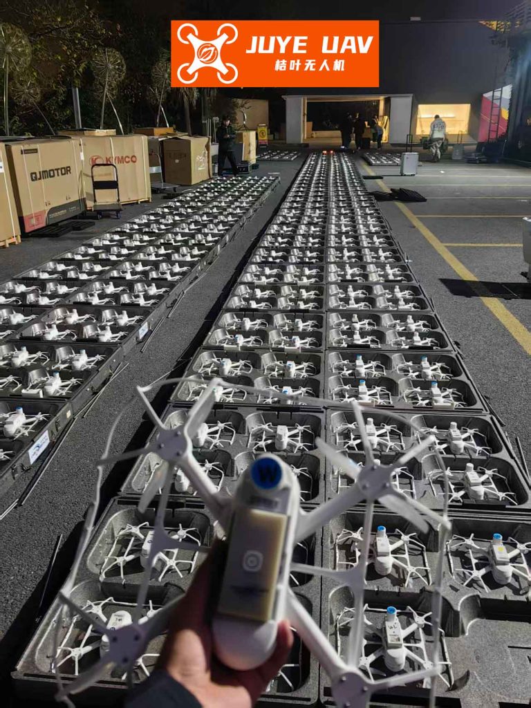
While research often focuses on applications like search and rescue or surveillance, the demands of a precision formation drone light show are equally, if not more, stringent. It requires flawless synchronization and geometric accuracy under conditions that introduce real-world imperfections, most notably communication delays between drones. These delays, if unaccounted for, can cause desynchronization, where drones move based on outdated neighbor information, leading to a blurred, unstable, or even unsafe formation. This article delves into the sophisticated control framework that enables a swarm of quadrotor drones to achieve and maintain a precise formation, explicitly compensating for these communication delays, thereby guaranteeing the flawless execution of a complex formation drone light show.
1. The Drone as a Dancer: System Modeling for Aerial Choreography
Consider a fleet of \( n \) quadrotor UAVs designated for a formation drone light show. We define \( j \) and \( k \) as indices for individual drones within the fleet, where \( j, k \in \{1, 2, …, n\} \). For the \( j \)-th drone, let \( \mathcal{B}_j \) denote its body-fixed frame and \( \mathcal{E} \) denote the inertial earth frame. Its position, linear velocity, and angular velocity in \( \mathcal{E} \) are defined as \( \mathbf{p}_j \in \mathbb{R}^3 \), \( \mathbf{v}_j \in \mathbb{R}^3 \), and \( \boldsymbol{\omega}_j \in \mathbb{R}^3 \), respectively.
Avoiding the singularities associated with Euler angles, we describe the orientation (attitude) of the drone using a unit quaternion \( \mathbf{Q}_j = [\eta_j, \mathbf{q}_j^T]^T \), where \( \mathbf{q}_j = [q_{j1}, q_{j2}, q_{j3}]^T \in \mathbb{R}^3 \) is the vector part and \( \eta_j \in \mathbb{R} \) is the scalar part, satisfying the constraint \( \mathbf{Q}_j^T \mathbf{Q}_j = \eta_j^2 + \mathbf{q}_j^T \mathbf{q}_j = 1 \).
The dynamic model for the \( j \)-th drone in the fleet, which forms the basis for controlling the formation drone light show, is separated into translational (position) and rotational (attitude) subsystems:
Translational Dynamics:
$$ \begin{align*}
\dot{\mathbf{p}}_j &= \mathbf{v}_j \\
m_j \dot{\mathbf{v}}_j &= m_j g \mathbf{e}_3 – U_j \mathbf{R}(\mathbf{Q}_j) \mathbf{e}_3
\end{align*} $$
where \( m_j \) is the mass, \( g \) is gravitational acceleration, \( \mathbf{e}_3 = [0, 0, 1]^T \), \( \mathbf{R}(\mathbf{Q}_j) \in SO(3) \) is the rotation matrix from \( \mathcal{B}_j \) to \( \mathcal{E} \) derived from the quaternion, and \( U_j \in \mathbb{R} \) is the total thrust control input, the primary force for altitude and movement in a formation drone light show.
Rotational Dynamics:
$$ \begin{align*}
\dot{\mathbf{q}}_j &= \frac{1}{2}(\eta_j \mathbf{I}_3 + \mathbf{S}(\mathbf{q}_j)) \boldsymbol{\omega}_j \\
\dot{\eta}_j &= -\frac{1}{2} \mathbf{q}_j^T \boldsymbol{\omega}_j \\
\mathbf{J}_j \dot{\boldsymbol{\omega}}_j &= -\mathbf{S}(\boldsymbol{\omega}_j) \mathbf{J}_j \boldsymbol{\omega}_j + \boldsymbol{\Gamma}_j
\end{align*} $$
Here, \( \mathbf{J}_j = \text{diag}(I_{jxx}, I_{jyy}, I_{jzz}) \in \mathbb{R}^{3 \times 3} \) is the inertia matrix, \( \mathbf{S}(\cdot) \) denotes the skew-symmetric matrix operator, and \( \boldsymbol{\Gamma}_j \in \mathbb{R}^3 \) is the moment (torque) control input, which governs the drone’s orientation.
The communication network for the formation drone light show is modeled by an undirected graph \( \mathcal{G} = (\mathcal{V}, \mathcal{E}, \mathcal{A}) \). The set of vertices \( \mathcal{V} \) represents the \( n \) drones. An edge \( (j, k) \in \mathcal{E} \) indicates that drones \( j \) and \( k \) can exchange information. The weighted adjacency matrix is \( \mathcal{A} = [a_{jk}] \in \mathbb{R}^{n \times n} \), with elements defined as:
$$ a_{jj} = 0, \quad a_{jk} = a_{kj} > 0 \text{ if } (j,k) \in \mathcal{E}, \quad a_{jk} = 0 \text{ otherwise}. $$
The relative position between drones \( j \) and \( k \) is \( \mathbf{p}_{jk}(t) = \mathbf{p}_j(t) – \mathbf{p}_k(t) \). The desired, constant offset that defines the show’s pattern is \( \boldsymbol{\delta}_{jk} = \boldsymbol{\delta}_j – \boldsymbol{\delta}_k \). The core challenge for a delayed formation drone light show is that due to communication latency \( \tau_{jk} \), drone \( j \) only receives \( \mathbf{p}_k(t – \tau_{jk}) \) at time \( t \). We denote this delayed relative position as \( \mathbf{p}_{jk}(t – \tau_{jk}) \).
Control Objective: Design the thrust \( U_j \) and moment \( \boldsymbol{\Gamma}_j \) for each drone such that, despite communication delays \( \tau_{jk} \), the fleet achieves:
$$ \lim_{t \to \infty} \mathbf{v}_j(t) = \mathbf{0}, \quad \text{and} \quad \lim_{t \to \infty} \mathbf{p}_{jk}(t) = \boldsymbol{\delta}_{jk}, \quad \forall (j,k) \in \mathcal{E}. $$
This means the entire formation drone light show converges to the desired static pattern and comes to a hover.
2. Core Algorithm: The Delayed Formation Control Framework
2.1 Virtual Force and Attitude Command Generation
The drone is underactuated: the thrust \( U_j \) only acts along the body’s z-axis. To achieve 3D position control, we must generate a virtual control force \( \mathbf{F}_j \in \mathbb{R}^3 \) in the inertial frame and then decompose it into the required thrust \( U_j \) and a desired attitude \( \mathbf{Q}_j^d \). We define:
$$ \mathbf{F}_j \triangleq m_j g \mathbf{e}_3 – U_j \mathbf{R}(\mathbf{Q}_j^d) \mathbf{e}_3. $$
The position dynamics can then be rewritten as:
$$ m_j \dot{\mathbf{v}}_j = \mathbf{F}_j – m_j \tilde{\mathbf{q}}_j, $$
where \( \tilde{\mathbf{q}}_j \) is a term capturing the coupling error between the current attitude \( \mathbf{Q}_j \) and the desired attitude \( \mathbf{Q}_j^d \).
To compensate for inter-drone coupling and communication delays inherent in a large-scale formation drone light show, we introduce an auxiliary system with state \( \boldsymbol{\phi}_j \in \mathbb{R}^3 \):
$$ \dot{\boldsymbol{\phi}}_j = -\kappa_j^{\phi} \boldsymbol{\phi}_j – \sum_{k=1}^{n} a_{jk} \left( \mathbf{p}_{jk}(t – \tau_{jk}) – \boldsymbol{\delta}_{jk} \right), $$
where \( \kappa_j^{\phi} > 0 \) is a design parameter. We then define an auxiliary velocity error \( \mathbf{z}_j = \mathbf{v}_j – \boldsymbol{\phi}_j \).
The virtual control force \( \mathbf{F}_j \) is designed as:
$$ \mathbf{F}_j = -\kappa_j^{z} \mathbf{z}_j – \sum_{k=1}^{n} a_{jk} \left( \mathbf{p}_{jk}(t – \tau_{jk}) – \boldsymbol{\delta}_{jk} \right), $$
where \( \kappa_j^{z} > 0 \) is another key control gain. From \( \mathbf{F}_j = [F_{jx}, F_{jy}, F_{jz}]^T \), we can finally compute the actual thrust command and the desired attitude quaternion for the formation drone light show drone:
$$ U_j = m_j \sqrt{(g – F_{jz}/m_j)^2 + F_{jx}^2 + F_{jy}^2}, $$
$$ \eta_j^d = \sqrt{\frac{1}{2}\left(1 + \frac{m_j g – F_{jz}}{U_j}\right)}, \quad \mathbf{q}_j^d = \frac{m_j}{2 U_j \eta_j^d} [-F_{jy}, F_{jx}, 0]^T. $$
The desired angular velocity \( \boldsymbol{\omega}_j^d \) can be derived from \( \dot{\mathbf{Q}}_j^d \).
2.2 Attitude Tracking Control
With \( \mathbf{Q}_j^d \) and \( \boldsymbol{\omega}_j^d \) defined, we now design the moment control \( \boldsymbol{\Gamma}_j \) to make the actual attitude \( \mathbf{Q}_j \) track these desired values precisely—a critical requirement for stable flight in a formation drone light show. Define the attitude error quaternion \( \tilde{\mathbf{Q}}_j = [\tilde{\eta}_j, \tilde{\mathbf{q}}_j^T]^T = (\mathbf{Q}_j^d)^{-1} \otimes \mathbf{Q}_j \) and the angular velocity error \( \tilde{\boldsymbol{\omega}}_j = \boldsymbol{\omega}_j – \mathbf{R}^T(\tilde{\mathbf{Q}}_j) \boldsymbol{\omega}_j^d \).
We introduce another auxiliary variable \( \boldsymbol{\beta}_j \in \mathbb{R}^3 \) and define \( \boldsymbol{\Omega}_j = \tilde{\boldsymbol{\omega}}_j – \boldsymbol{\beta}_j \). The derivative \( \dot{\boldsymbol{\Omega}}_j \) can be expressed in a tractable form. The robust attitude tracking controller is then designed as:
$$ \boldsymbol{\Gamma}_j = \boldsymbol{\Upsilon}_j + \mathbf{J}_j \dot{\boldsymbol{\beta}}_j – c_1 \mathbf{J}_j \boldsymbol{\Omega}_j, $$
where \( \boldsymbol{\Upsilon}_j \) contains Coriolis, coupling, and compensation terms, and \( c_1 > 0 \). The auxiliary variable \( \boldsymbol{\beta}_j \) is designed as:
$$ \boldsymbol{\beta}_j = -c_2 \tilde{\mathbf{q}}_j + \frac{U_j}{m_j} \mathbf{\Phi}_j^T \mathbf{z}_j, $$
with \( c_2 > 0 \) and \( \mathbf{\Phi}_j \) being a known matrix function of the attitude error. To handle potential disturbances and ensure smooth control, the final control law for the \( l \)-th component (\( l = 1,2,3 \)) of \( \boldsymbol{\Gamma}_j \) is:
$$ \Gamma_{j}^{(l)} = – \frac{ \Upsilon_j^{(l)} \Omega_j^{(l)} }{ \sqrt{ (\Upsilon_j^{(l)})^2 + (\Omega_j^{(l)})^2 } + \epsilon_j(t) }, $$
where \( \epsilon_j(t) > 0 \) is a time-varying, integrable function that smoothens the control action.
3. Stability Analysis: Proving the Show Goes On
The ultimate question for any formation drone light show designer is: “Is this control strategy mathematically guaranteed to work under delay?” We answer this via Lyapunov stability theory. We assume the communication delays are bounded, i.e., \( \tau_{jk} \le \bar{\tau} \), a known constant.
Theorem (Formation Stability under Delay): Consider the drone dynamics and the communication graph \( \mathcal{G} \). Using the control laws for \( U_j \) and \( \boldsymbol{\Gamma}_j \) defined above, if the control gains are selected such that:
$$ \kappa_j^{z} > \frac{1}{2}\left( \kappa_j^{\phi} + \frac{\kappa_j^{\phi} \bar{\tau}}{2} + \frac{1}{2\bar{\tau}} \right) > 0, $$
and \( \kappa_j^{\phi} > \sum_{k=1}^n a_{jk}(\kappa_j^{z} – \kappa_k^{z}) \), then the closed-loop system is globally asymptotically stable. This means for any initial state:
$$ \lim_{t \to \infty} \mathbf{v}_j(t) = \mathbf{0}, \quad \lim_{t \to \infty} \mathbf{p}_{jk}(t) = \boldsymbol{\delta}_{jk}, \quad \lim_{t \to \infty} \tilde{\mathbf{q}}_j(t) = \mathbf{0}, \quad \lim_{t \to \infty} \tilde{\eta}_j(t) = 1. $$
The formation drone light show achieves perfect geometric formation and hovering.
Proof Sketch: The proof constructs a composite Lyapunov-Krasovskii functional candidate \( V(t) = V_p(t) + V_a(t) \):
$$ \begin{aligned}
V_p(t) &= \frac{1}{2}\sum_{j=1}^n \mathbf{z}_j^T \mathbf{z}_j + \frac{1}{2}\sum_{j=1}^n \boldsymbol{\phi}_j^T \boldsymbol{\phi}_j + \frac{1}{4}\sum_{j=1}^n \sum_{k=1}^n a_{jk} (\mathbf{p}_{jk} – \boldsymbol{\delta}_{jk})^T (\mathbf{p}_{jk} – \boldsymbol{\delta}_{jk}) \\
&\quad + \frac{1}{2}\sum_{j=1}^n \sum_{k=1}^n a_{jk} \frac{\bar{\tau}}{\kappa} \int_{t-\bar{\tau}}^{t} \int_{s}^{t} \mathbf{v}_k^T(\rho)\mathbf{v}_k(\rho) d\rho ds, \\
V_a(t) &= \frac{1}{2}\sum_{j=1}^n \boldsymbol{\Omega}_j^T \mathbf{J}_j \boldsymbol{\Omega}_j + 2c_2 \sum_{j=1}^n (1 – \tilde{\eta}_j).
\end{aligned} $$
Using the system dynamics and the control laws, the derivative \( \dot{V}(t) \) is shown to be bounded by:
$$ \dot{V}(t) \le -\sum_{j=1}^n \left( \kappa_j^{v} \mathbf{v}_j^T \mathbf{v}_j + \kappa_j^{\phi} \boldsymbol{\phi}_j^T \boldsymbol{\phi}_j + c_1 \boldsymbol{\Omega}_j^T \boldsymbol{\Omega}_j + 4c_2 \tilde{\mathbf{q}}_j^T \tilde{\mathbf{q}}_j \right) + \sum_{j=1}^n 3\epsilon_j(t), $$
where \( \kappa_j^{v} > 0 \) is a positive constant derived from the gain conditions. Since \( \int_0^\infty \epsilon_j(t) dt \) is finite, applying Barbalat’s lemma proves that all error terms \( \mathbf{v}_j, \boldsymbol{\phi}_j, \boldsymbol{\Omega}_j, \tilde{\mathbf{q}}_j \) converge to zero. Convergence of \( \boldsymbol{\phi}_j \) to zero, combined with its dynamics, directly implies \( \mathbf{p}_{jk}(t) – \boldsymbol{\delta}_{jk} \to \mathbf{0} \), completing the proof.
4. Parameter Selection and Performance Trade-offs
Successfully deploying this controller for a formation drone light show requires careful tuning of the key parameters. Their roles and trade-offs are summarized below:
| Parameter | Symbol | Role / Effect | Design Consideration |
|---|---|---|---|
| Virtual Force Gain | \( \kappa_j^{z} \) | Governs convergence speed of position/velocity tracking. A higher gain gives faster response. | Must satisfy the inequality with \( \bar{\tau} \) and \( \kappa_j^{\phi} \). Excessively high gains may amplify noise and demand high thrust. |
| Auxiliary System Gain | \( \kappa_j^{\phi} \) | Damps the auxiliary variable \( \boldsymbol{\phi}_j \), controlling the delay compensation dynamics. | Must be sufficiently large relative to differences in neighbors’ \( \kappa_k^{z} \). Affects the transient interplay between drones. |
| Attitude Damping Gain | \( c_1 \) | Directly dampens the angular rate error \( \boldsymbol{\Omega}_j \), smoothing attitude maneuvers. | Higher values lead to crisper, more damped attitude tracking but require higher torque authority. |
| Attitude Error Gain | \( c_2 \) | Provides proportional feedback on attitude error \( \tilde{\mathbf{q}}_j \), driving the attitude to the desired value. | Essential for accurate attitude convergence. Too high can cause overshoot or oscillations in the orientation. |
| Smoothing Function | \( \epsilon_j(t) \) | Prevents chattering in the attitude control law ( \( \boldsymbol{\Gamma}_j \) ) and ensures control signal smoothness. | Typically a small, exponentially decaying function (e.g., \( e^{-0.1t} \)). Final value impacts steady-state attitude error. |
5. Simulation of a Formation Light Show
To validate the theory, we simulate a fleet of \( n=4 \) drones performing a formation drone light show maneuver. The drones start from random positions and velocities and must form a square pattern in the XY-plane with a side length of 4 meters, while reaching a common altitude (Z=10m). Communication delays between drones are set asymmetrically (e.g., \( \tau_{12}=0.1s, \tau_{13}=0.2s \), etc.), with a known upper bound \( \bar{\tau} = 0.3s \).
Using the described control framework with appropriately chosen gains satisfying the stability conditions, the drones successfully achieve the formation. The key results are:
- Formation Convergence: The 3D trajectories show the drones smoothly transitioning from their scattered initial positions to the precise vertices of the square, definitively proving the controller’s ability to manage a coordinated formation drone light show.
- Velocity Regulation: The velocity components of all drones converge asymptotically to zero, confirming the fleet achieves a stable hover in the final formation—a non-negotiable requirement for a static display in a formation drone light show.
- Attitude Tracking: The components of the attitude error quaternion vector \( \tilde{\mathbf{q}}_j \) converge to zero, while the scalar part \( \tilde{\eta}_j \) converges to 1. This demonstrates that each drone’s physical orientation perfectly aligns with the attitude required to generate the necessary forces for formation keeping, despite the dynamic coupling.
This simulation provides a digital testament to the algorithm’s efficacy, demonstrating that a stable, precise formation drone light show is achievable even when drones communicate with time-lagged information.
6. Conclusion and Future of Aerial Choreography
This article has presented a comprehensive, nonlinear control solution for orchestrating a formation drone light show in the presence of realistic communication delays. By leveraging a unit quaternion-based model to avoid singularities, introducing an auxiliary system for delay and coupling compensation, and designing decoupled yet cooperative controllers for thrust and torque, we have established a rigorous framework. The provided Lyapunov-based stability analysis offers clear, verifiable conditions on controller gains, transforming the design from an art into a science.
The implications extend beyond entertainment. The core technology—reliable, delay-tolerant formation control of underactuated UAVs—is directly applicable to precision agricultural spraying, collaborative payload transport, and automated warehouse inventory systems using drone fleets. The mathematical choreography developed for the formation drone light show is, at its heart, a generic solution for multi-agent coordination under communication constraints.
Future work will focus on scaling this approach to swarms of hundreds or thousands of drones, incorporating obstacle avoidance for dynamic environments, and adapting the formation in real-time to create truly interactive and adaptive formation drone light show experiences. The convergence of control theory, robotics, and communication networks continues to push the boundaries of what is possible, turning the night sky into a dynamic canvas governed by the elegant laws of mathematics.