
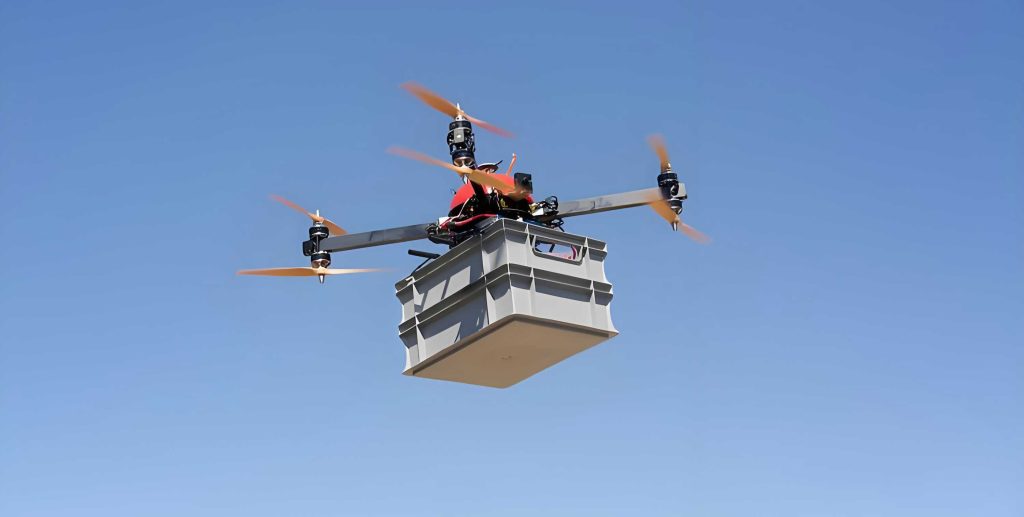
Ion wind propulsion, based on the electrohydrodynamic (EHD) effect, represents a paradigm shift in aerial vehicle design. This solid-state technology generates thrust through the movement of ions in a strong electric field, eliminating the need for traditional moving parts like propellers or turbines. For UAV drones, this translates to near-silent operation, rapid response, and high reliability with minimal mechanical complexity. The core of an ion wind propulsion system is its electrode array, where structural configuration critically determines performance metrics such as thrust density and thrust-to-power ratio—key parameters for viable UAV drone applications. This study employs COMSOL Multiphysics finite element software to systematically analyze and compare parallel-placed and cross-placed electrode structures and their array configurations, focusing on optimizing effective thrust and efficiency for compact ion wind UAV drones.
1. Fundamentals and Mathematical Model of Ion Wind Propulsion
The operational principle involves a high-voltage, low-current corona discharge between asymmetrical electrodes—typically a thin emitter (e.g., wire) and a larger collector. Air molecules near the sharp emitter are ionized, and these ions are accelerated towards the collector by the electric field. Through countless collisions with neutral air molecules, they transfer momentum, creating a bulk air flow known as ion wind or EHD flow. The reaction force of this accelerated air mass provides the thrust for propulsion. The performance for UAV drones is evaluated primarily by the thrust force (F) and the thrust-to-power ratio (γ), defined as thrust per unit input electrical power.
The simulation model couples electrostatic, charge transport, and fluid dynamics physics. A unipolar ion drift model is adopted for computational efficiency, where the ionization zone is simplified by a prescribed charge density boundary condition at the emitter surface based on the Kaptzov assumption.
The governing equations are as follows. The electric potential (ϕ) and field (E) are described by Poisson’s equation and its gradient:
$$ \nabla^2 \phi = -\frac{\rho_c}{\epsilon_0}, \quad \mathbf{E} = -\nabla \phi $$
where $\rho_c$ is the space charge density and $\epsilon_0$ is the permittivity of free space.
The current density (J), driven by ion mobility (µ), is given by:
$$ \mathbf{J} = \mu \rho_c \mathbf{E} $$
and satisfies the charge conservation law:
$$ \nabla \cdot \mathbf{J} = 0 $$
The Coulomb body force (F_e) acting on the fluid, whose reaction is the thrust, is:
$$ \mathbf{F_e} = \rho_c \mathbf{E} $$
This body force is the source term in the incompressible Navier-Stokes equations for fluid flow:
$$ \nabla \cdot \mathbf{u} = 0 $$
$$ \rho (\mathbf{u} \cdot \nabla) \mathbf{u} = -\nabla p + \eta \nabla^2 \mathbf{u} + \mathbf{F_e} $$
where $\mathbf{u}$ is the fluid velocity, $\rho$ is air density, $p$ is pressure, and $\eta$ is the dynamic viscosity.
The thrust per unit length (f) and thrust-to-power ratio (γ) are calculated as:
$$ f = \int \mathbf{F_e} \, dA \quad \text{(integrated over the domain)} $$
$$ \gamma = \frac{f_{effective}}{U I} $$
where $f_{effective}$ is the horizontal (thrust-producing) component of $f$, $U$ is the applied voltage, and $I$ is the total discharge current. Optimizing these parameters is crucial for the endurance and payload capacity of UAV drones.
2. Analysis of Parallel-Placed Electrode Structure
The foundational geometry for ion wind thrusters is the parallel-placed configuration, where a single wire emitter is aligned with a single airfoil collector. Understanding the influence of various parameters on this basic cell is essential before exploring complex arrays for UAV drones.
A parametric study was conducted with the following base parameters: emitter wire radius r = 0.1 mm, collector airfoil (modeled as an ellipse with semi-major axis m = 50 mm, semi-minor axis n = 10 mm), electrode gap d = 60 mm, and applied voltage U = 40 kV. The influence of each parameter was investigated independently.
2.1 Influence of Applied Voltage (U)
As voltage increases from 20 kV to 60 kV, the electric field and space charge density intensify. This leads to a higher discharge current and greater Coulomb force. Consequently, both total thrust and effective thrust increase significantly. However, the input power ($U \times I$) increases at a faster rate than thrust. Therefore, while thrust is proportional to current, the thrust-to-power ratio is inversely related to voltage. A balance must be struck for efficient UAV drone operation.
2.2 Influence of Electrode Gap (d)
A smaller gap results in a stronger electric field for a given voltage, increasing current and thrust. However, a very small gap risks electrical breakdown and leads to a lower thrust-to-power ratio due to disproportionate power consumption. The thrust-to-power ratio improves almost linearly with increasing gap, but thrust decreases. An optimal gap exists for maximizing overall system performance for UAV drones.
2.3 Influence of Emitter Radius (r)
A smaller emitter radius creates a higher electric field gradient at its surface, enhancing corona onset and space charge density. This yields higher thrust and current. The thrust-to-power ratio shows a slight decrease with a smaller radius, but the gain in thrust is more substantial. Thus, a thin wire emitter is generally preferable for UAV drone thrusters.
2.4 Influence of Collector Size (n)
Increasing the size (specifically the leading-edge curvature) of the collector enlarges the effective area for ion collection. This allows for a higher sustainable discharge current and greater thrust, with only a modest reduction in the thrust-to-power ratio. However, for practical UAV drones, the increased aerodynamic drag and weight of a larger collector must be considered.
The trends from this analysis are summarized in the table below, providing a guideline for initial electrode design in ion wind UAV drones.
| Parameter | Trend for Thrust (f) | Trend for Thrust-to-Power Ratio (γ) | Practical Consideration for UAV Drones |
|---|---|---|---|
| Voltage (U) ↑ | Increases | Decreases | Requires high-voltage power supply; balance needed. |
| Gap (d) ↑ | Decreases | Increases | Larger structure; risk of breakdown at small d. |
| Emitter Radius (r) ↓ | Increases | Slightly Decreases/Stable | Preferred for high thrust density. |
| Collector Size (n) ↑ | Increases | Slightly Decreases | Trade-off with drag and weight. |
3. Cross-Placed Electrode Structure: Concept and Single-Cell Analysis
An alternative to the standard parallel layout is the cross-placed structure. In this configuration, a single wire emitter is positioned centrally between two collector airfoils. The key geometric parameters are the fixed emitter-to-collector distance (d) and the angle (θ) between the line connecting the emitter to a collector and the horizontal axis. This arrangement inherently defines the array spacing (a) between adjacent collector leading edges as $a = 2d \sin(\theta)$.
For a fair comparison with the parallel structure (with gap d=50 mm), a cross-placed cell (Structure D) was analyzed with d=50 mm, varying θ (and thus a). The effective thrust increases with array spacing ‘a’, but the rate of increase diminishes. The thrust-to-power ratio gradually decreases because the component of ion drift contributing to vertical force increases with θ, leading to higher current and power consumption without a proportional gain in horizontal (effective) thrust.
Critically, at the same electrode gap (d=50 mm), the cross-placed cell (D) yields a higher effective thrust (0.29 N/m at a=30 mm) compared to the parallel cell (A, 0.19 N/m). This demonstrates the potential benefit of the cross-placed geometry for enhancing the thrust output of UAV drones, albeit with careful management of efficiency.
4. Comparative Analysis of Electrode Array Structures for UAV Drones
Practical ion wind propulsion systems for UAV drones consist of multiple electrode pairs arranged in arrays. The interaction between adjacent cells significantly affects overall performance. We compare arrays built from parallel (Structures B, C) and cross-placed (Structures D, E, F, G) base cells.
4.1 Small Arrays: Structures B, D, and E
Structure B is a 2-emitter, 2-collector parallel array. Structure D is the single cross-placed cell. Structure E is a small cross-placed array with 3 emitters and 2 collectors. Results show that at large array spacings (a > 60 mm), Structure B provides the best compromise with good thrust and the highest thrust-to-power ratio. Structure D offers a marginal thrust increase over B but lower efficiency. Structure E, while producing the highest thrust, suffers from a significantly lower thrust-to-power ratio due to its much higher discharge current and power draw, making it less ideal for efficient UAV drones at these spacings.
4.2 Extended Arrays for Practical UAV Drones: Structures C, F, and G
To evaluate configurations relevant to actual UAV drone design, larger arrays were simulated. Structure C is an 8-emitter, 8-collector parallel array. Structure F is a cross-placed array with 7 emitters and 8 collectors. Structure G has 9 emitters and 8 collectors. The performance trends reveal a crucial insight for compact UAV drone design.
At small array spacings (a ≤ 40 mm), the cross-placed arrays, particularly Structure G, outperform the parallel array. For instance, at a = 40 mm:
$$ f_{eff, C} = 1.10 \, \text{N/m}, \quad \gamma_{C} = 4.11 \, \text{N/kW} $$
$$ f_{eff, G} = 1.27 \, \text{N/m}, \quad \gamma_{G} = 4.23 \, \text{N/kW} $$
Structure G provides a 15.45% increase in effective thrust and a 2.92% increase in thrust-to-power ratio compared to Structure C.
At a = 50 mm:
$$ f_{eff, C} = 1.23 \, \text{N/m}, \quad \gamma_{C} = 4.31 \, \text{N/kW} $$
$$ f_{eff, G} = 1.57 \, \text{N/m}, \quad \gamma_{G} = 4.07 \, \text{N/kW} $$
Here, Structure G delivers a substantial 27.6% boost in effective thrust with only a 5.6% reduction in thrust-to-power ratio.
The physical mechanism behind this advantage is twofold. First, the cross-placed configuration offers a larger effective ion collection area per unit frontal area, enabling higher thrust generation. Second, at small array spacings, the mutual interference between adjacent cells in a cross-placed array leads to a more favorable distribution of the Coulomb body force. Simulation results show that Structure G concentrates more force in the primary thrust-producing region between the emitter and collector and generates less reverse-direction force upstream of the emitters compared to Structure C. This leads to more efficient conversion of electrical energy into net thrust, a vital factor for the power-constrained systems on UAV drones.
The comparative performance at key spacings is summarized below:
| Array Spacing (a) | Structure | Effective Thrust (N/m) | Thrust-to-Power Ratio (N/kW) | Advantage for UAV Drones |
|---|---|---|---|---|
| 40 mm | C (Parallel) | 1.10 | 4.11 | G offers higher thrust and efficiency. |
| G (Cross) | 1.27 | 4.23 | ||
| 50 mm | C (Parallel) | 1.23 | 4.31 | G offers significantly higher thrust with minimal efficiency penalty. |
| G (Cross) | 1.57 | 4.07 |
5. Conclusion
This simulation study comprehensively investigated electrode structures for ion wind propulsion, with a focus on applications for UAV drones. The analysis of parallel-placed electrodes established the fundamental trade-offs between thrust, efficiency, and geometric parameters. The exploration of cross-placed electrode structures revealed their inherent potential for higher thrust generation compared to parallel layouts at the same inter-electrode gap.
The most significant finding pertains to the design of electrode arrays for compact ion wind UAV drones. While simple parallel arrays perform adequately at larger spacings, cross-placed electrode arrays (exemplified by Structure G) demonstrate a pronounced advantage at smaller array spacings (e.g., 40-50 mm). In this regime, they can deliver a substantial increase in effective thrust—over 15% to 27%—while maintaining, or even slightly improving, the thrust-to-power ratio compared to equivalent parallel arrays.
This makes the cross-placed electrode array configuration particularly suitable for the design of compact, high-thrust-density ion wind propulsion systems. For UAV drones, where maximizing thrust and payload within a limited wingspan or fuselage volume is critical, adopting an optimized cross-placed electrode array can lead to significant performance enhancements, bringing silent, solid-state EHD propulsion closer to practical, widespread application in unmanned aerial systems.