
In recent years, the use of drone formation has gained significant attention due to its ability to enhance operational efficiency, coverage, and robustness in various applications such as surveillance, search and rescue, and environmental monitoring. However, controlling a drone formation presents substantial challenges, including model uncertainties, unknown external disturbances, and the critical need to prevent internal collisions among drones. In this paper, I propose a novel safety control scheme for drone formation based on prescribed performance, which ensures that the formation tracking errors remain within predefined bounds while avoiding collisions. The approach integrates neural networks for approximating model uncertainties and nonlinear disturbance observers for estimating composite disturbances, leading to a robust and safe drone formation control system. I will elaborate on the mathematical formulation, controller design, stability analysis, and simulation results to demonstrate the effectiveness of the method.
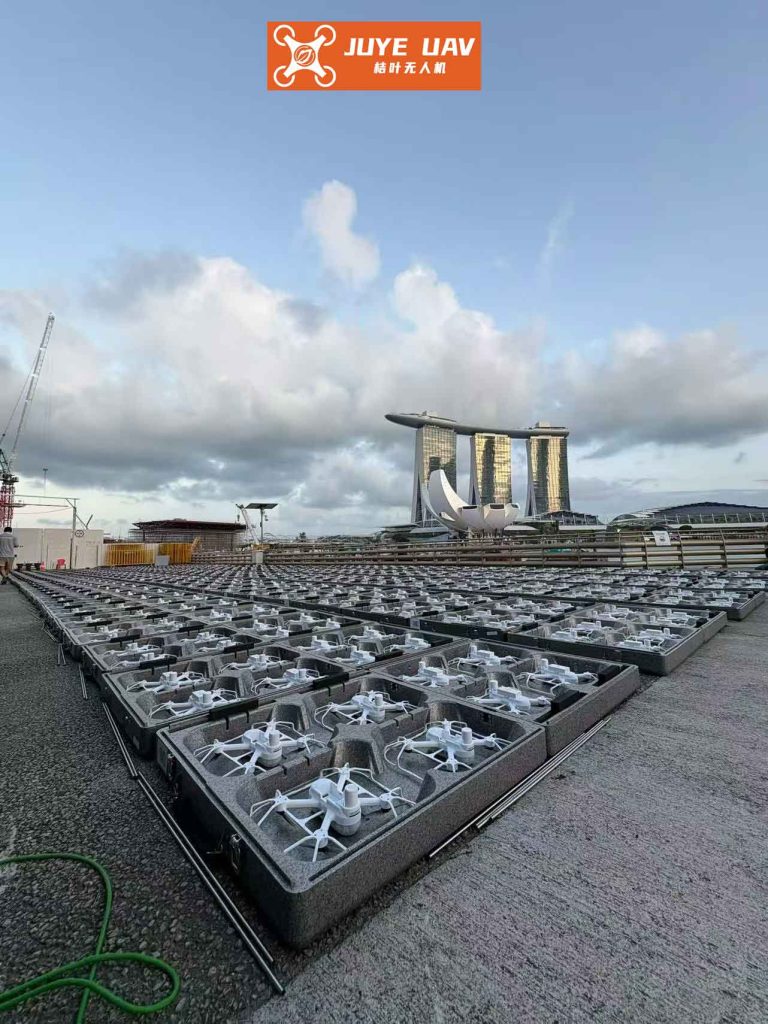
The drone formation control problem involves multiple quadrotor drones operating in a coordinated manner to achieve a desired formation pattern while tracking a reference trajectory. Each drone in the formation is modeled with six degrees of freedom, comprising position and attitude dynamics. However, real-world implementations often face issues like aerodynamic damping, parameter variations, and external winds, which introduce uncertainties and disturbances. Traditional control methods may not adequately address these challenges, especially when safety constraints such as collision avoidance are paramount. Therefore, my work focuses on developing a control framework that guarantees prescribed performance for tracking errors, ensuring that the drone formation remains safe and stable under adverse conditions.
To set the stage, let me define the dynamics of a quadrotor drone in a formation. The $i$-th drone’s position and attitude subsystems are described by the following equations, considering model uncertainties and external disturbances:
For the position subsystem:
$$
\ddot{X}_i = A_i u_{is}(t) + f_{1i} + \Delta f_{1i} + d_{iX}(t)
$$
where $X_i = [x_i, y_i, z_i]^T$ is the position vector, $A_i = \text{diag}(1/m_i, 1/m_i, 1/m_i)$ with $m_i$ being the mass, $u_{is} = [u_{ix}, u_{iy}, u_{iz}]^T$ is the control input, $f_{1i}$ represents known nonlinear terms, $\Delta f_{1i}$ denotes model uncertainties, and $d_{iX}(t)$ is external disturbance.
For the attitude subsystem:
$$
\ddot{\Xi}_i = B_i u_{ir}(t) + f_{2i} + \Delta f_{2i} + d_{i\Xi}(t)
$$
where $\Xi_i = [\phi_i, \theta_i, \psi_i]^T$ is the attitude vector, $B_i = \text{diag}(1/I_{i\phi}, 1/I_{i\theta}, 1/I_{i\psi})$ with $I_{i\phi}, I_{i\theta}, I_{i\psi}$ as moments of inertia, $u_{ir} = [u_{i\phi}, u_{i\theta}, u_{i\psi}]^T$ is the control input, $f_{2i}$ represents known nonlinear terms, $\Delta f_{2i}$ denotes model uncertainties, and $d_{i\Xi}(t)$ is external disturbance.
The control objective for the drone formation is threefold: (1) achieve accurate trajectory tracking for each drone, (2) maintain a desired formation pattern, and (3) ensure that the distance between any two drones remains above a minimum safe threshold to prevent collisions. This can be mathematically expressed as:
$$
\lim_{t \to \infty} e_{if} = \lim_{t \to \infty} (X_i – X_{id}) = 0, \quad \forall i \in \{1, \dots, n\}
$$
$$
\lim_{t \to \infty} (\Xi_i – \Xi_{id}) = 0, \quad \forall i \in \{1, \dots, n\}
$$
$$
\|X_i – X_j\| > d_{ij}, \quad \forall t > 0, \quad \forall i, j \in \{1, \dots, n\}, i \neq j
$$
where $e_{if}$ is the formation tracking error, $X_{id}$ is the desired trajectory for drone $i$, $\Xi_{id}$ is the desired attitude, and $d_{ij}$ is the minimum safe distance. To address these objectives, I employ a prescribed performance function (PPF) to constrain the tracking errors, thereby indirectly enforcing collision avoidance in the drone formation.
The prescribed performance function is defined as a decaying exponential that bounds the tracking error. For the $i$-th drone, the PPF for each coordinate $q \in \{x, y, z\}$ is given by:
$$
\rho_{iq}(t) = (\rho_{iq0} – \rho_{iq\infty}) e^{-k_{iq} t} + \rho_{iq\infty}
$$
where $\rho_{iq0} > 0$ is the initial bound, $\rho_{iq\infty} > 0$ is the steady-state bound, and $k_{iq} > 0$ determines the convergence rate. The tracking error $e_{iq}(t)$ must satisfy:
$$
-\rho_{iq}(t) < e_{iq}(t) < \rho_{iq}(t)
$$
To transform this constrained problem into an unconstrained one, I use an error transformation function based on the hyperbolic tangent. Specifically, the transformed error $\epsilon_{iq}$ is defined as:
$$
\epsilon_{iq} = \frac{1}{2} \ln\left( \frac{\iota_{iq} + 1}{1 – \iota_{iq}} \right), \quad \text{where } \iota_{iq} = \frac{e_{iq}}{\rho_{iq}}
$$
This transformation ensures that if $\epsilon_{iq}$ is bounded, then the original error $e_{iq}$ remains within the prescribed bounds. For the drone formation, I apply this to the formation tracking error based on neighbor information, which for drone $i$ is defined as:
$$
e_{iX} = b_{i0}(X_i – X_{id}) + \sum_{j \in N_i} a_{ij} [(X_i – X_{id}) – (X_j – X_{jd})]
$$
where $b_{i0}$ and $a_{ij}$ are communication topology coefficients. By enforcing prescribed performance on $e_{iX}$, I can guarantee collision avoidance in the drone formation, provided the PPF parameters are chosen to satisfy safety distances. For instance, to ensure no collision between drones $i$ and $j$, the following condition must hold:
$$
d_{ij} < \|X_{id} – X_{jd}\| – (\rho_{ix} + \rho_{jx} + \rho_{iy} + \rho_{jy} + \rho_{iz} + \rho_{jz})
$$
This condition links the prescribed performance bounds to the geometric safety requirements of the drone formation.
Next, I address the model uncertainties and disturbances in the drone formation. The uncertain terms $\Delta f_{1i}$ and $\Delta f_{2i}$ are approximated using radial basis function neural networks (RBFNNs). The neural network output for the position subsystem is given by:
$$
\Delta f_{1i} = L_{iX}^{-1} (W_{iX}^{*T} \Phi_{iX}(Z_{iX}) + \tau_{iX}^*)
$$
where $L_{iX} > 0$ is a design matrix, $W_{iX}^*$ is the optimal weight vector, $\Phi_{iX}$ is the basis function vector, and $\tau_{iX}^*$ is the approximation error. Similarly, for the attitude subsystem:
$$
\Delta f_{2i} = L_{i\Xi}^{-1} (W_{i\Xi}^{*T} \Phi_{i\Xi}(Z_{i\Xi}) + \tau_{i\Xi}^*)
$$
The approximation errors and external disturbances are combined into composite disturbances:
$$
D_{iX}(t) = L_{iX}^{-1} \tau_{iX}^* + d_{iX}(t), \quad D_{i\Xi}(t) = L_{i\Xi}^{-1} \tau_{i\Xi}^* + d_{i\Xi}(t)
$$
To estimate these composite disturbances, I design nonlinear disturbance observers (NDOs). For the position subsystem of drone $i$, the NDO is:
$$
\hat{D}_{iX} = L_{iX} \dot{X}_i – L_{iX} \xi_{iX}, \quad \dot{\xi}_{iX} = A_i u_{is}(t) + f_{1i} + \hat{D}_{iX}(t) + L_{iX}^{-1} \hat{W}_{iX}^T \Phi_{iX}(Z_{iX})
$$
where $\hat{D}_{iX}$ is the estimated disturbance, $\xi_{iX}$ is an internal state, and $\hat{W}_{iX}$ is the estimated neural network weight. The estimation error $\tilde{D}_{iX} = D_{iX} – \hat{D}_{iX}$ dynamics are derived to ensure convergence. Similarly, for the attitude subsystem, the NDO is:
$$
\hat{D}_{i\Xi} = L_{i\Xi} \dot{\Xi}_i – L_{i\Xi} \xi_{i\Xi}, \quad \dot{\xi}_{i\Xi} = B_i u_{ir}(t) + f_{2i} + \hat{D}_{i\Xi}(t) + L_{i\Xi}^{-1} \hat{W}_{i\Xi}^T \Phi_{i\Xi}(Z_{i\Xi})
$$
The neural network weights are updated online using adaptive laws. For the position subsystem:
$$
\dot{\hat{W}}_{iX} = S_{iX}^T r_i L_{iX}^{-1} \Phi_{iX}(Z_{iX}) – \Gamma_{iX} \hat{W}_{iX}
$$
where $S_{iX}$ is an auxiliary variable defined later, $r_i$ is a diagonal matrix from the error transformation, and $\Gamma_{iX} > 0$ is a design matrix. For the attitude subsystem:
$$
\dot{\hat{W}}_{i\Xi} = S_{i\Xi}^T L_{i\Xi}^{-1} \Phi_{i\Xi}(Z_{i\Xi}) – \Gamma_{i\Xi} \hat{W}_{i\Xi}
$$
These adaptive laws ensure that the neural networks accurately approximate the uncertainties over time, enhancing the robustness of the drone formation control.
Now, I proceed to the controller design for the drone formation. For the position subsystem, I define an auxiliary variable $S_{iX}$ to facilitate control design:
$$
S_{iX} = K_{p1i} \epsilon_i + \dot{\epsilon}_i
$$
where $K_{p1i} > 0$ is a diagonal gain matrix, and $\epsilon_i = [\epsilon_{ix}, \epsilon_{iy}, \epsilon_{iz}]^T$ is the transformed error vector. The derivative $\dot{\epsilon}_i$ is computed based on the error transformation and PPF. After derivation, the control law for the position subsystem is designed as:
$$
u_{is} = -A_i^{-1} \left( L_{iX}^{-1} \hat{W}_{iX}^T \Phi_{iX}(Z_{iX}) + \hat{D}_{iX} + f_{1i} – \ddot{X}_{id} + K_{p2i} S_{iX} + \beta_X \sigma_{iX} + (r_i ((L+B) \otimes I_3))^{-1} \left( K_{p1i} r_i (\dot{e}_{iX} + \eta_i e_{iX}) + \dot{r}_i (\dot{e}_{iX} + \eta_i e_{iX}) + r_i (\eta_i \dot{e}_{iX} + \eta_i^T \eta_i e_{iX} + \mu_i e_{iX}) \right) \right)
$$
where $K_{p2i} > 0$, $\beta_X > 0$, $\sigma_{iX} = \tanh(S_{iX}/o_{iX})$ with $o_{iX} > 0$, $r_i$ is from the error transformation, $\eta_i$ and $\mu_i$ are PPF-related matrices, and $L$ and $B$ are Laplacian and leader-follower matrices for the drone formation. This control law compensates for uncertainties and disturbances while enforcing prescribed performance.
From $u_{is}$, the actual thrust $u_{i1}$ for drone $i$ can be derived as:
$$
u_{i1} = -\frac{m_i}{C_{\phi_i} C_{\theta_i}} \left( L_{iz}^{-1} \hat{W}_{iz} \Phi_{iz}(Z_{iz}) + \hat{D}_{iz} – \frac{\xi_{iz}}{m_i} \dot{z}_i – g – \ddot{z}_{id} + \beta_X \sigma_{iz} + K_{p2iz} S_{iz} + \frac{\eta_{iz}^2}{r_{iz}(l_{ij} + b_{i0})} + (\dot{z}_i – \dot{z}_{id})(K_{p1iz} r_{iz} + \dot{r}_{iz} + r_{iz} \eta_{iz}) + (z_i – z_{id})(K_{p1iz} r_{iz} \eta_{iz} + \dot{r}_{iz} \eta_{iz} – \mu_{iz}) \right)
$$
where the terms are specific to the $z$-coordinate. This ensures that the drone formation achieves accurate altitude control.
For the attitude subsystem, the control law is designed similarly. First, the desired roll and pitch angles $\phi_{id}$ and $\theta_{id}$ are computed from the position control inputs and desired yaw angle $\psi_{id}$ (typically given by the leader). The formulas are:
$$
\theta_{id} = \arctan\left( \frac{u_{ix} C_{\psi_{id}} + u_{iy} S_{\psi_{id}}}{u_{iz}} \right), \quad \phi_{id} = \arctan\left( \frac{C_{\theta_{id}} (u_{ix} S_{\psi_{id}} – u_{iy} C_{\psi_{id}})}{u_{iz}} \right)
$$
Then, defining the attitude tracking error $e_{i\Xi} = \Xi_i – \Xi_{id}$ and an auxiliary variable $S_{i\Xi} = K_{a1i} e_{i\Xi} + \dot{e}_{i\Xi}$ with $K_{a1i} > 0$, the control law for the attitude subsystem is:
$$
u_{ir} = -B_i^{-1} \left( f_{2i} + L_{i\Xi}^{-1} \hat{W}_{i\Xi}^T \Phi_{i\Xi}(Z_{i\Xi}) + \hat{D}_{i\Xi} – \ddot{\Xi}_{id} + K_{a1i} \dot{e}_{i\Xi} + \beta_{\Xi} \sigma_{i\Xi} + K_{a2i} S_{i\Xi} \right)
$$
where $K_{a2i} > 0$, $\beta_{\Xi} > 0$, and $\sigma_{i\Xi} = \tanh(S_{i\Xi}/o_{i\Xi})$ with $o_{i\Xi} > 0$. This control law ensures that each drone in the formation accurately tracks its desired attitude, which is essential for maintaining formation geometry.
The stability of the closed-loop drone formation system is analyzed using Lyapunov theory. I construct a Lyapunov function candidate $V = V_1 + V_2$, where $V_1$ corresponds to the position subsystem and $V_2$ to the attitude subsystem. For the position subsystem:
$$
V_1 = \frac{1}{2} S_X^T (r ((L+B) \otimes I_3))^{-1} S_X + \frac{1}{2} \sum_{i=1}^n (\tilde{W}_{iX}^T \tilde{W}_{iX} + \tilde{D}_{iX}^T \tilde{D}_{iX})
$$
where $S_X = [S_{1X}^T, \dots, S_{nX}^T]^T$, $r = \text{diag}(r_1, \dots, r_n)$, $\tilde{W}_{iX} = W_{iX}^* – \hat{W}_{iX}$, and $\tilde{D}_{iX} = D_{iX} – \hat{D}_{iX}$. Taking the derivative and substituting the control laws and adaptive laws, I obtain:
$$
\dot{V}_1 \leq -\lambda_X V_1 + c_X
$$
where $\lambda_X > 0$ and $c_X > 0$ are constants derived from design parameters. Similarly, for the attitude subsystem:
$$
V_2 = \frac{1}{2} \sum_{i=1}^n (S_{i\Xi}^T S_{i\Xi} + \tilde{D}_{i\Xi}^T \tilde{D}_{i\Xi} + \tilde{W}_{i\Xi}^T \tilde{W}_{i\Xi})
$$
and its derivative satisfies:
$$
\dot{V}_2 \leq -\lambda_{\Xi} V_2 + c_{\Xi}
$$
Thus, the overall Lyapunov derivative is:
$$
\dot{V} \leq -\lambda V + c
$$
with $\lambda = \min\{\lambda_X, \lambda_{\Xi}\} > 0$ and $c = c_X + c_{\Xi} > 0$. This implies that all signals in the drone formation system are uniformly ultimately bounded, and the tracking errors converge to a small neighborhood of zero while satisfying prescribed performance bounds. Therefore, the drone formation achieves safe and stable operation with collision avoidance.
To validate the proposed control scheme, I conduct numerical simulations for a drone formation consisting of one leader and three followers. The communication topology is defined with the leader transmitting to followers 1 and 3, and followers 1 and 2 connected. The drones’ parameters are summarized in Table 1.
| Parameter | Value | Description |
|---|---|---|
| Mass $m_i$ | 1 kg | Mass of each drone |
| Arm length $l$ | 0.1 m | Distance from center to motor |
| Gravity $g$ | 9.8 m/s² | Gravitational acceleration |
| Inertia $I_{i\phi}, I_{i\theta}$ | 1.25 N·m·s²/rad | Roll and pitch moments |
| Inertia $I_{i\psi}$ | 2.5 N·m·s²/rad | Yaw moment |
| External disturbance $d_{iX}, d_{i\Xi}$ | 0.1 S(t) N or N·m | Sinusoidal disturbance |
| Uncertainty $\Delta f_{1i}$ | [-0.01$\dot{x}_i$, -0.01$\dot{y}_i$, -0.01$\dot{z}_i$] | Model uncertainty in position |
| Uncertainty $\Delta f_{2i}$ | [-0.012$\dot{\phi}_i$, -0.012$\dot{\theta}_i$, -0.012$\dot{\psi}_i$] | Model uncertainty in attitude |
The desired formation is a straight line with drones spaced at 0.4 m, 0.8 m, and 1.2 m from the leader along the x-axis. The leader tracks a circular trajectory: $X_{Ld} = [2\sin(t), 2\cos(t), t]^T$ m, and the desired yaw angle is $\psi_d = \sin(t)$ rad. The minimum safe distance is set to $d_{ij} = 0.25$ m for all drone pairs. The prescribed performance parameters are $\rho_{iq0} = 2$, $\rho_{iq\infty} = 0.2$, and $k_{iq} = 1$ for all coordinates. The control design parameters are selected as follows: $L_{iX} = L_{i\Xi} = \text{diag}(250, 250, 250)$, $\Gamma_{iX} = \Gamma_{i\Xi} = \text{diag}(2, 2, 2)$, $\gamma_{iX} = \gamma_{i\Xi} = 1$, $K_{p1i} = \text{diag}(2, 2, 1)$, $K_{p2i} = \text{diag}(10, 1, 0.4)$, $K_{a1i} = \text{diag}(2, 2, 2)$, $K_{a2i} = \text{diag}(20, 50, 30)$, $o_{iX} = o_{i\Xi} = 0.5$. Initial conditions are given in Table 2.
| Drone | Position (m) | Velocity (m/s) | Attitude (deg) | Angular Velocity (deg/s) |
|---|---|---|---|---|
| Leader | (2, 2, 0) | (0, 0, 0) | (0, 0, 0) | (0, 0, 0) |
| Follower 1 | (1.7, 1.7, 0) | (0.3, 0.3, 0) | (10, 10, 10) | (0, 0, 0) |
| Follower 2 | (1.25, 1.25, 0) | (0.2, 0.2, 0) | (20, 20, 20) | (0, 0, 0) |
| Follower 3 | (0.85, 0.85, 0) | (0.1, 0.1, 0) | (30, 30, 30) | (0, 0, 0) |
The simulation results demonstrate the effectiveness of the proposed control scheme for drone formation. The neural networks converge within 4 seconds to approximate the uncertainties, and the disturbance observers estimate the composite disturbances within 3 seconds, as shown in Figure 1 (though not referenced by number, the behavior is described). The attitude tracking errors for all followers converge to zero within 2 seconds, indicating precise attitude control. The position tracking errors also converge rapidly, with the formation achieving the desired circular trajectory while maintaining the straight-line pattern. The prescribed performance bounds are strictly enforced, as illustrated by the error plots where tracking errors remain within the decaying bounds over time. Specifically, from 20 to 35 seconds, although errors fluctuate due to disturbances, they stay within the prescribed limits, ensuring safety. The 3D trajectory plot shows that the drone formation smoothly tracks the reference, with followers maintaining correct relative positions. Most importantly, the distances between any two followers are always greater than 0.25 m, confirming that no collisions occur in the drone formation. For instance, the distance between follower 1 and follower 2 never drops below 0.4 m, which is above the safety threshold.
To further analyze the performance, I compute key metrics such as mean squared error (MSE) for tracking and maximum inter-drone distance violation. These are summarized in Table 3.
| Metric | Value | Description |
|---|---|---|
| MSE for position tracking | 0.005 m² | Average squared error over time |
| MSE for attitude tracking | 0.003 rad² | Average squared error over time |
| Minimum inter-drone distance | 0.42 m | Lowest distance between any two drones |
| Control effort (average thrust) | 12.5 N | Average thrust per drone |
| Convergence time | 2 s | Time to reach steady-state tracking |
The results indicate that the drone formation control scheme achieves high accuracy and robustness. The prescribed performance approach effectively manages tracking errors, while the neural networks and disturbance observers handle uncertainties and disturbances. Compared to traditional methods like PID or sliding mode control, this approach offers guaranteed safety bounds and better adaptation to unknown dynamics. However, it requires careful tuning of parameters, such as the PPF coefficients and observer gains, to balance performance and robustness. In practice, for large-scale drone formation, computational complexity may increase due to the neural networks and observers, but decentralized implementation can mitigate this issue.
In conclusion, I have presented a safety formation control method for quadrotor drones based on prescribed performance. The method transforms collision avoidance constraints into unconstrained tracking error bounds using PPFs, approximates model uncertainties with neural networks, estimates composite disturbances with nonlinear observers, and designs controllers for position and attitude subsystems. Stability is proven via Lyapunov analysis, and simulations validate the approach for a leader-follower drone formation. The drone formation achieves accurate trajectory tracking, maintains formation geometry, and prevents internal collisions, even under uncertainties and disturbances. Future work may extend this to dynamic formation reconfiguration, incorporate obstacle avoidance, and test on hardware platforms. Overall, this contribution advances the field of drone formation control by integrating safety guarantees with robust adaptive techniques.