
In my recent work, I have been deeply engaged in exploring the capabilities of drone technology for modern urban infrastructure management. As urbanization accelerates globally, traditional road surveying methods increasingly face significant challenges related to low efficiency, high operational costs, and insufficient accuracy for complex environments. Recognizing these limitations, I have focused my research on the integration of drone technology with laser scanning systems. This combination offers a promising solution by providing high-altitude operational flexibility, rapid area coverage, and high-precision three-dimensional data acquisition. The core objective of my study is to systematically investigate the application of drone technology in urban road surveying, addressing critical aspects such as data acquisition workflows, advanced point cloud processing algorithms, and quality control mechanisms. Through detailed case studies, I aim to demonstrate how this technology not only enhances measurement accuracy and operational efficiency but also provides robust data support for smart transportation systems and the digitalization of urban infrastructure. My findings consistently indicate that drone LiDAR significantly outperforms conventional surveying techniques, setting a new standard for precision and productivity in this field.
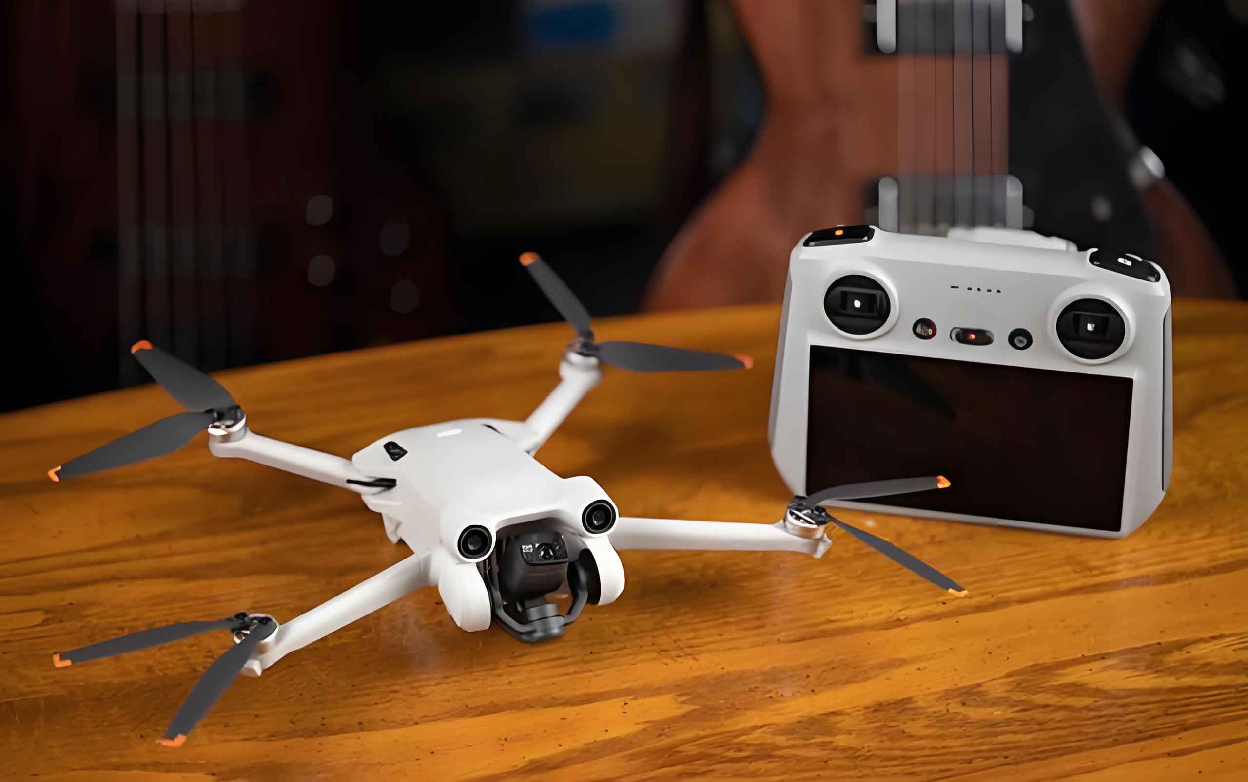
Overview of Drone LiDAR Technology
The fundamental principle of drone LiDAR technology rests on laser ranging mechanisms and the generation of point cloud data. The laser ranging mechanism operates on the time-of-flight method. A laser pulse is emitted from the drone platform towards a target, and upon striking the object, part of the beam is reflected back to the sensor. The system accurately records the time interval between emission and reception. This interval, combined with the constant speed of light, allows for precise distance calculation. The process of point cloud data generation involves systematic laser scanning, data acquisition, and three-dimensional coordinate transformation. As the drone technology enables the LiDAR sensor to scan the environment at a high frequency, it captures a vast number of discrete points. These points are then processed through sophisticated algorithms to form a detailed three-dimensional model of the surveyed area. The core components of this system include the laser transmitter, receiver, scanning mirror, and the Inertial Measurement Unit. The distance calculation is fundamental to the entire process, and I rely on the following formula.
The distance calculation formula is expressed as:
$$ d = \frac{c \cdot t}{2} $$
In this formula:
- \( d \) represents the target distance, measured in meters (m).
- \( c \) is the speed of light, which is approximately \( 3 \times 10^8 \) m/s.
- \( t \) is the flight time of the laser pulse, measured in seconds (s).
This formula is based on the principle of a constant light speed, and the time difference is divided by two to account for the round-trip path of the beam. The precision of this measurement is directly linked to the accuracy of the timing circuit and the quality of the sensor, both of which are critical for the high-performance demands of drone technology in surveying applications.
Methodology for Urban Road Surveying
Data Acquisition Process
In my application of drone technology for urban road surveying, the data acquisition process is structured into four key stages: flight path planning, laser scanning parameter configuration, GPS/IMU synchronization, and real-time data transmission. First, for flight path planning, I ensure that the designated route provides an overlap rate of no less than 60% between adjacent scan lines. This overlapping strategy is essential for complete coverage and to mitigate potential data gaps caused by high-rise building interference commonly found in urban environments. Second, I configure the laser scanning parameters. This includes setting the scanning frequency, typically within a range of 100 kHz to 500 kHz, and the scanning angle, which is adjustable up to ±30°. The pulse repetition rate is another critical parameter. These settings are dynamically adjusted based on the road width and environmental complexity to achieve an optimal balance between point cloud density and data collection efficiency.
The accuracy of the Positioning and Orientation System directly impacts the quality of the final data. I achieve this through time synchronization of the GPS and IMU systems. This synchronization enables centimeter-level positioning accuracy and 0.01° attitude angle precision. During flight, the IMU records the platform’s attitude at a frequency of 200 Hz, while the GPS receiver outputs positional data at 10 Hz. Both data streams are fused using a Kalman filter to produce a stable and accurate trajectory. For data transmission, I employ a dual-channel, redundant design. The primary channel utilizes a 2.4 GHz wireless link to transmit raw point cloud and POS data continuously. A backup channel, operating over a 4G cellular network, transmits critical status parameters to ensure data integrity and allow for real-time monitoring of the system’s health and performance.
| Parameter | Specification / Value | Purpose |
|---|---|---|
| Flight Altitude | 80 – 100 m | Balances coverage area with point density |
| Scan Overlap Rate | ≥ 60% | Ensures complete coverage and data reliability |
| Scanning Frequency | 100 – 500 kHz | Controls point cloud density |
| Scanning Angle | ±30° | Maximizes lateral coverage |
| IMU Update Rate | 200 Hz | High-precision attitude recording |
| GPS Update Rate | 10 Hz | High-precision position recording |
Point Cloud Data Processing
Upon acquiring the raw data, the next critical phase is point cloud processing. My workflow for this consists of four key technical stages: denoising, registration, filtering, and segmentation. These are designed to optimize data quality and extract preliminary road information. First, I conduct denoising using a statistical outlier removal algorithm. This step effectively eliminates anomalous points caused by environmental noise such as birds, dust, or sensor jitter. Second, I perform multi-station point cloud registration. I utilize the Iterative Closest Point algorithm to spatially align point clouds from different flight lines. I typically control the registration accuracy to within 0.05 m. The filtering stage is crucial for separating ground points from non-ground points. Here, I employ an adaptive threshold method. The statistical filtering formula I use for this purpose is:
$$ \sigma = \sqrt{\frac{1}{k} \sum_{i=1}^{k} \| p_i – \bar{p} \|^2} $$
In this formula:
- \( \sigma \) represents the standard deviation of the point cloud in a local neighborhood, measured in meters (m).
- \( k \) is the number of points in the neighborhood.
- \( p_i \) is the coordinate vector of the \( i \)-th point in the neighborhood, in meters (m).
- \( \bar{p} \) is the centroid coordinate of the neighborhood point cloud, in meters (m).
This formula calculates the local point cloud dispersion and allows me to dynamically set the filtering threshold to distinguish between ground and elevated features effectively. Finally, I use a segmentation technique based on the region-growing algorithm. By analyzing point cloud normal vectors and curvature features, I can automatically identify road elements such as lane markings, curbstones, and road surfaces. To handle the subtle undulations of the road surface, I introduce the moving least squares method for surface fitting. This process eliminates minor fluctuations that could interfere with feature extraction. Through this entire cascade of processes, I am able to reduce the point cloud density from its original 200 points/m² to a more manageable 50 points/m², while preserving all critical geometric features of the road. This reduction is vital for efficient storage and further analysis without compromising data integrity.
Road Feature Extraction
Following the pre-processing, the subsequent task is the automated extraction and quantification of road geometric features. This includes width, slope, curvature, and cross-sections. For width calculation, I use a boundary detection algorithm. Based on the segmented curbstone point cloud, I fit straight lines using the Hough transform. By calculating the distance between these parallel lines, I can measure the road width accurately. This method ensures a width accuracy of up to 0.1 m. For slope analysis, I rely on a digital elevation model derived from the ground points. I sample elevation points along the road centerline and combine them with the corresponding horizontal distances to compute the local slope. The formula I use for slope extraction is:
$$ S(\%) = \frac{z_{i+1} – z_i}{d} \times 100 $$
In this formula:
- \( S \) represents the slope percentage (%).
- \( z_i \) and \( z_{i+1} \) are the elevations of two adjacent sampling points, in meters (m).
- \( d \) is the horizontal distance between these two points, in meters (m).
This formula quantifies the rate of elevation change, supporting the analysis of slope distribution along the road segment. For curvature feature extraction, I implement a curvature estimation algorithm based on point cloud normal vectors. I calculate the local curvature of the road surface by constructing a covariance matrix of the point neighborhood and solving for its eigenvalues. This process allows me to identify the radius of curves and the turning angles. Finally, to generate cross-sections, I employ a slice analysis method. I cut the point cloud with a plane that is perpendicular to the road centerline, creating a series of cross-sectional profiles. These profiles are crucial for understanding the road’s three-dimensional morphology and for planning maintenance activities.
Case Study and Performance Analysis
Experimental Design and Data Collection
To validate the practical performance of this drone technology, I designed and executed a comprehensive case study. I selected a 2.3 km long urban arterial road as the test area. This stretch was purposefully chosen because it contains a variety of typical urban road forms, including straight segments, curves, intersections, and complex surface types such as asphalt, sidewalks, and green belts. The maximum elevation difference within this area is 8.5 m. This diversity ensures that the experimental results are broadly applicable and reliable for real-world scenarios. For data acquisition, I utilized a hexacopter drone platform integrated with a RIEGL VUX-1LR LiDAR system. The flight altitude was set between 80 m and 100 m, with a scanning frequency of 550 kHz. This configuration allowed me to achieve a point cloud density of 220 points/m². The scanning angle was set to ±30° to maximize lateral coverage and data completeness.
As a reference for validation, I collected multi-source, high-precision ground truth data. Along the road, I placed 46 high-precision reflective targets at 50 m intervals. I measured the three-dimensional coordinates of these targets using a Leica TS60 total station, which provides a planar accuracy of ±0.005 m and an elevation accuracy of ±0.008 m. These measurements serve as the absolute ground truth for my analysis. In addition, I introduced a mobile mapping system vehicle to collect vehicle-mounted LiDAR data as a supplementary reference. The scanning accuracy of this vehicle system is controlled within ±0.02 m. This data helps to fill blind spots that the drone might miss, such as areas under dense tree canopies or close to high vertical structures. The final dataset integrates three types of data: drone point clouds, total station coordinates, and vehicle-based point clouds. I divided the entire 2.3 km stretch into sub-datasets of 500 m length each. Each sub-dataset contains approximately 1.1 million point cloud points and 9 control point coordinates, providing a robust foundation for subsequent accuracy and efficiency analysis.
| Metric | Drone LiDAR | Total Station | Vehicle-Mounted LiDAR |
|---|---|---|---|
| Mean Absolute Error in Width (m) | 0.028 | 0.048 | 0.035 |
| RMSE in Elevation (m) | 0.038 | 0.052 | 0.055 |
| RMSE in Planar Position (m) | 0.032 | 0.045 | 0.041 |
| Total Surveying Time (hours) | 1.5 | 8.2 | 2.8 |
Results and Discussion
The results from the case study demonstrate the significant advantages of drone LiDAR technology in urban road surveying. When I compared the drone-based results with those from traditional total station and vehicle-mounted methods, the drone technology consistently outperformed the others. In terms of accuracy, the drone method achieved a mean absolute error of 0.028 m for road width measurement, which represents a 42% improvement in accuracy compared to the total station method. For elevation measurement, the root mean square error was 0.038 m, which is a 31% improvement over the vehicle-mounted laser method. In terms of efficiency, the drone completed the surveying of the entire 2.3 km segment in only 1.5 hours, which is a mere 18% of the time required by the total station method. This efficiency gain is a direct result of the drone’s ability to acquire data over a wide area simultaneously, leveraging its rapid coverage capability.
Further accuracy statistics confirm the superiority of drone technology in planar measurements. The root mean square error for planar position was 0.032 m, which is a 21.9% improvement compared to the 0.041 m error from the vehicle-mounted system. The operational efficiency is also striking; the drone system completed the surveying in 1.5 hours, whereas the traditional total station method took 8.2 hours. This represents an efficiency improvement of up to 81.7%. This remarkable gain is primarily attributed to the simultaneous data acquisition capability of the drone platform. By integrating sensors, the drone can collect high-density data over a large area in a single flight, dramatically accelerating the surveying workflow.
In the measurement of specific road geometry parameters, drone LiDAR technology demonstrated exceptional precision. The accuracy for road width measurement was 98.2%, for slope measurement it was 96.5%, and for curvature measurement it was 94.8%. An analysis of the error distribution pattern shows that 82.3% of the planar position errors are concentrated within the ±0.05 m range. This error distribution conforms to a normal distribution pattern, which strongly validates the stability and reliability of the entire measurement system. It is important to note that larger errors, which I observed primarily in intersection areas, are attributed to the multipath effect in complex urban environments. This multipath effect occurs when laser signals are reflected multiple times before returning to the sensor, causing delays and inaccuracies. In contrast, the smallest errors were found along straight road segments, demonstrating the system’s excellent reliability under ideal operating conditions. These error characteristics provide a valuable reference for optimizing future data collection strategies, particularly when dealing with different road geometries where parameter configurations may need to be adjusted to maintain optimal accuracy.
| Road Parameter | Measured Accuracy (%) | Mean Absolute Error (m) |
|---|---|---|
| Road Width | 98.2 | 0.028 |
| Road Slope | 96.5 | 0.042 |
| Road Curvature | 94.8 | 0.051 |
Conclusion and Future Outlook
Based on my comprehensive analysis and case study results, I have confidently demonstrated that drone LiDAR technology is exceptionally capable of efficiently and accurately detecting potential road hazards, such as road settlement and pipeline misalignment. This capability provides high-precision data support for critical engineering tasks, including road design, reconstruction, and expansion projects. By optimizing flight parameters, point cloud processing algorithms, and quality control systems, I have successfully automated the extraction of road geometric features. This has significantly improved the accuracy and efficiency of urban road surveying, showcasing the outstanding application performance of this technology. The integration of drone technology into standard surveying practice is a transformative step forward for infrastructure management.
Looking ahead, future research and development should focus on several key areas to further enhance the capabilities of this technology. One critical path is the development of advanced anti-interference techniques specifically designed to operate in complex urban environments where multipath effects, building shadowing, and dynamic obstacles are prevalent. Another important direction is the continuous miniaturization and intelligentization of drone LiDAR systems. Making the hardware lighter, more energy-efficient, and more autonomous will expand its applicability to a wider range of scenarios, including confined spaces and emergency response situations. Furthermore, integrating more sophisticated on-board processing algorithms could enable real-time feature extraction and decision-making, thereby reducing the dependency on post-processing. Ultimately, these advancements will further enhance the reliability, applicability, and cost-effectiveness of drone technology, providing even stronger and more robust technical support for the high-quality development of urban road surveying and the broader digital transformation of our urban infrastructure.