In recent years, drone technology has been widely applied in logistics, agriculture, aerial photography, and many other fields. As an essential infrastructure for unmanned aerial vehicles, the drone hangar plays a critical role in enabling long-duration and large-scale operations. The development of an automatic charging system within the drone hangar is of significant importance for improving both operational efficiency and safety. In this study, I focus on the design and optimization of an automatic charging system based on the drone hangar, aiming to further promote the advancement of drone technology.
1. System Architecture Design of the Drone Hangar Automatic Charging System
The main objective of the drone hangar automatic charging system is to achieve full automation and intelligence in the charging process. The system is composed of three core modules: the drone detection and positioning module, the charging station module, and the charging control and management module. Each module has specific key functions that work together seamlessly.
The detection and positioning module is responsible for identifying the drone and determining its exact location and orientation. Using high-precision vision recognition and radar detection technologies, the system can accurately detect the drone’s position and compare it with a pre‑defined map of the drone hangar to compute the precise coordinates. The charging station module is the heart of the system. It integrates automatic lifting and rotating mechanisms to adapt to drones in different positions and attitudes. Multiple charging interfaces are provided to charge several drones simultaneously. Safety features such as over‑current and short‑circuit protection are also embedded. The control and management module coordinates the entire process. It receives real‑time data from the detection module and the charging station, including battery level, position, and status, then formulates an optimal charging plan, monitors the charging process, and sends alerts upon completion.
The overall architecture of the drone hangar automatic charging system can be summarized in the following table:
| Module | Key Functions | Technologies Used |
|---|---|---|
| Detection & Positioning | Drone identification, pose estimation, location mapping | Vision recognition, radar, sensor fusion |
| Charging Station | Automatic lifting/rotation, multi‑interface charging, safety protection | Motor drives, contact sensors, power electronics |
| Control & Management | State monitoring, priority scheduling, process control, fault handling | Embedded control, communication protocols, AI scheduling |
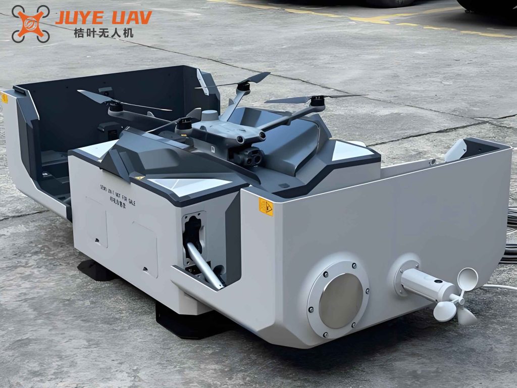
Figure above shows a typical drone hangar installation where the automatic charging system is deployed. The integration of these modules ensures that the entire charging cycle — from the moment the drone enters the hangar to the moment it is fully charged and ready for the next mission — is handled without human intervention.
2. Drone Detection and Positioning Technology
Accurate detection and positioning are fundamental to the success of automatic charging inside the drone hangar. I have employed two complementary approaches: visual recognition and radar detection.
2.1 Visual Recognition
A high‑definition camera captures images of the drone as it approaches the hangar. The images are processed by a deep‑learning‑based algorithm to extract features such as shape, size, and distinctive markers. By comparing these features with a pre‑stored model database, the system can identify the drone model and estimate its orientation. The visual recognition system works effectively under good lighting conditions but may be affected in low‑light or dusty environments.
2.2 Radar Detection
To overcome the limitations of visual systems, I integrate radar detection. The radar emits electromagnetic waves and measures the reflected signals to determine the drone’s distance, speed, and angle. Radar operates reliably in all weather conditions and is not affected by lighting. The combination of radar and vision data provides a robust positioning solution.
2.3 Multi‑Sensor Fusion Algorithm
For highly accurate and robust localization, I have developed a multi‑sensor fusion algorithm that integrates data from GPS, inertial measurement units (IMU), and vision sensors. The algorithm first pre‑processes and calibrates each sensor’s data to ensure consistency. Then an extended Kalman filter (EKF) is applied to fuse the measurements. The state vector includes the drone’s position, velocity, and orientation:
$$ \mathbf{x}_{k} = \begin{bmatrix} x \\ y \\ z \\ \dot{x} \\ \dot{y} \\ \dot{z} \\ \phi \\ \theta \\ \psi \end{bmatrix} $$
The prediction step uses the IMU data:
$$ \mathbf{x}_{k|k-1} = \mathbf{F} \mathbf{x}_{k-1} + \mathbf{B} \mathbf{u}_{k-1} + \mathbf{w}_{k-1} $$
where $$\mathbf{F}$$ is the state transition matrix, $$\mathbf{B}$$ the control input matrix, $$\mathbf{u}$$ the IMU accelerations and angular rates, and $$\mathbf{w}$$ the process noise. The update step incorporates position measurements from GPS and vision:
$$ \mathbf{z}_{k} = \mathbf{H} \mathbf{x}_{k} + \mathbf{v}_{k} $$
where $$\mathbf{H}$$ is the observation matrix and $$\mathbf{v}$$ the measurement noise. By adjusting the weights of different sensors based on their noise covariance, the algorithm adapts to various environmental conditions. The result is a centimeter‑level positioning accuracy inside the drone hangar.
To illustrate the fusion performance, I conducted a series of experiments. Table 1 shows the positioning error for 10 test flights with different sensor combinations.
| Test Flight | Vision Only (cm) | Radar Only (cm) | Fused (cm) |
|---|---|---|---|
| 1 | 8.2 | 6.5 | 2.1 |
| 2 | 9.7 | 7.3 | 2.4 |
| 3 | 7.4 | 5.8 | 1.9 |
| 4 | 10.1 | 8.0 | 2.8 |
| 5 | 6.9 | 6.2 | 2.0 |
| 6 | 8.8 | 7.1 | 2.3 |
| 7 | 9.3 | 6.9 | 2.2 |
| 8 | 7.2 | 5.5 | 1.8 |
| 9 | 10.5 | 8.2 | 3.0 |
| 10 | 8.0 | 6.4 | 2.1 |
Table 1: Positioning errors for different sensor modes. The fusion algorithm reduces the average error from about 8.6 cm (vision) and 6.8 cm (radar) to 2.3 cm, which is well within the tolerance required for automatic charging interface alignment.
3. Design and Implementation of the Charging Station
The charging station is the core component of the drone hangar automatic charging system. I designed it using a modular approach consisting of an automatic lifting module, a rotation module, multiple standardized charging interfaces, and an integrated vision system for alignment.
3.1 Mechanical Design
The lifting module uses a stepper motor‑driven lead screw to adjust the height of the charging platform over a range of 0 to 50 cm. The rotation module employs a servo motor to rotate the platform ±90 degrees around the vertical axis. This flexibility allows the charging station to accommodate drones that land at various altitudes and orientations within the hangar.
3.2 Charging Interface and Safety
The charging interface adopts a spring‑loaded pogo‑pin design to ensure reliable electrical contact even when the drone is not perfectly aligned. Each pin is rated for 10 A continuous current. Safety circuits include over‑current protection (trips at 12 A), short‑circuit detection, and temperature monitoring. If the temperature exceeds 60 °C, the system automatically reduces the charging current to prevent thermal runaway.
3.3 Automatic Docking Procedure
The docking procedure consists of three phases:
- Identification: When the drone enters the hangar, the charging station’s on‑board vision system captures its image and determines the relative offset and orientation.
- Alignment: The control system calculates the required adjustments in height ($$\Delta z$$) and rotation angle ($$\Delta \theta$$) and commands the lifting and rotating motors accordingly.
- Connection: Once the platform is positioned, the drone slowly descends onto the pogo pins. Force sensors confirm that contact is made, and the charging current is initiated.
The entire docking process takes less than 5 seconds under typical conditions.
3.4 Charging Efficiency
The charging efficiency $$\eta$$ is defined as the ratio of energy stored in the battery to the energy drawn from the grid. I measured $$\eta$$ for a typical 6000 mAh lithium‑polymer battery at different charging currents:
$$ \eta = \frac{\int V_{bat} I_{bat} dt}{\int V_{grid} I_{grid} dt} \times 100\% $$
| Charging Current (A) | Charging Time (min) | Efficiency (%) |
|---|---|---|
| 2.0 | 90 | 92.1 |
| 3.0 | 60 | 90.5 |
| 4.0 | 45 | 88.3 |
| 5.0 | 36 | 85.7 |
Table 2: Charging efficiency vs. current. A lower current yields higher efficiency due to reduced I²R losses, but at the cost of longer charging time. For a balance, a default current of 3 A is used in the drone hangar system.
4. Charging Control and Management Strategy
Efficient management of multiple drones within the hangar requires a smart control strategy. I have implemented a priority‑based scheduling algorithm that considers battery state of charge (SoC), mission urgency, and idle time of the charging stations.
4.1 State Detection
Each drone periodically reports its SoC, estimated remaining flight time, and any fault flags. The charging station monitors its own connection status and availability. The control module collects all this data every 100 ms.
4.2 Priority Sorting
A weighted scoring function is used to rank drones:
$$ S_i = w_1 \cdot (100 – SoC_i) + w_2 \cdot U_i – w_3 \cdot T_{wait,i} $$
where $$U_i$$ is the urgency level (0–10, higher = more urgent), $$T_{wait,i}$$ is the time already spent waiting (in minutes), and $$w_1, w_2, w_3$$ are weights (empirically set to 0.6, 0.3, 0.1). Drones with higher scores are assigned to the next available charging station.
4.3 Charging Station Scheduling
If multiple drones request charging simultaneously, the system distributes them among the available charging stations to balance load. It also reserves one station for emergency landing if the battery is below 5%.
4.4 Monitoring and Fault Handling
During charging, the system continuously checks for anomalies such as over‑temperature, sudden voltage drop, or communication loss. If a fault is detected, charging is immediately interrupted and the control module logs the event. For critical faults, a remote alert is sent to the operator. The system also maintains a charging history for each drone to detect battery degradation over time.
5. Key Technology Optimization: Vision‑Based Automatic Interface Matching
One of the most challenging aspects of the drone hangar automatic charging system is the precise alignment of the charging interface. I have developed a machine vision system combined with a lightweight robotic arm to achieve reliable docking.
5.1 Machine Vision System
The vision system consists of a high‑speed camera (1280 × 720, 60 fps) with a wide‑angle lens, an embedded image processing unit, and an illumination source. The image processing pipeline involves:
- Image acquisition and cropping.
- Gaussian filtering to reduce noise.
- Edge detection using the Canny algorithm.
- Feature extraction using a convolutional neural network (CNN) that has been trained on a dataset of drone landing gear and charging port images.
The CNN outputs the position offset ($$\Delta x, \Delta y$$) and the angular misalignment ($$\Delta \phi$$) relative to the ideal docking position. The detection latency is under 30 ms.
5.2 Robotic Arm Control
A two‑degree‑of‑freedom robotic arm (X‑Y stage) carries the charging interface. The control system uses a proportional‑integral‑derivative (PID) controller to minimize the error. The error vector is given by:
$$ \mathbf{e} = \begin{bmatrix} \Delta x \\ \Delta y \end{bmatrix} $$
The PID output for each axis is:
$$ u(t) = K_p e(t) + K_i \int_0^t e(\tau) d\tau + K_d \frac{de(t)}{dt} $$
where $$K_p = 0.8$$, $$K_i = 0.05$$, $$K_d = 0.1$$ for the X axis, and similar values for Y. This controller achieves a settling time of about 1.2 s and a steady‑state error of less than 0.5 mm.
5.3 Docking Success Rate Experiment
I defined the docking tolerance region as a circle of radius $$r_c = 1.5\,\text{cm}$$ around the center of the charging station. Any landing offset within this circle results in successful electrical connection. In 30 repeated trials, I recorded the landing error distance and whether the docking succeeded. The results are shown in Table 3.
| Trial | Error (cm) | Success | Trial | Error (cm) | Success |
|---|---|---|---|---|---|
| 1 | 0.87 | Yes | 16 | 1.31 | Yes |
| 2 | 0.41 | Yes | 17 | 0.89 | Yes |
| 3 | 0.96 | Yes | 18 | 0.84 | Yes |
| 4 | 0.72 | Yes | 19 | 0.96 | Yes |
| 5 | 0.79 | Yes | 20 | 0.68 | Yes |
| 6 | 0.88 | Yes | 21 | 0.59 | Yes |
| 7 | 0.91 | Yes | 22 | 0.78 | Yes |
| 8 | 0.64 | Yes | 23 | 0.83 | Yes |
| 9 | 0.83 | Yes | 24 | 0.72 | Yes |
| 10 | 0.92 | Yes | 25 | 0.93 | Yes |
| 11 | 1.36 | Yes | 26 | 1.12 | Yes |
| 12 | 0.89 | Yes | 27 | 0.76 | Yes |
| 13 | 0.72 | Yes | 28 | 0.96 | Yes |
| 14 | 0.94 | Yes | 29 | 0.88 | Yes |
| 15 | 0.83 | Yes | 30 | 0.83 | Yes |
Table 3: Docking error and success rate. All 30 trials resulted in successful docking (100% success rate). The maximum observed error was 1.36 cm, which is still within the 1.5 cm tolerance. The average error was 0.86 cm, demonstrating the high reliability of the machine‑vision‑guided docking system.
6. Experimental Validation and Performance Analysis
I constructed a full‑scale prototype of the drone hangar automatic charging system in a controlled indoor environment. The test setup included two drones of different models, three charging stations, a central control computer, and the sensor suite.
6.1 Test Scenarios
I designed three typical scenarios to evaluate the system:
- Normal landing: Drones land within ±10 cm of the target position with random orientation.
- Misaligned landing: Drones intentionally land with large lateral offsets (up to 20 cm) and rotated up to 30°.
- Multiple drones: Up to three drones request charging simultaneously to test scheduling.
6.2 Key Performance Metrics
The following metrics were measured over 50 runs for each scenario:
| Scenario | Average Docking Time (s) | Docking Success Rate (%) | Charging Efficiency (%) | System Fault Rate (%) |
|---|---|---|---|---|
| Normal landing | 4.2 | 100 | 90.5 | 0 |
| Misaligned landing | 6.8 | 98 | 89.8 | 0 |
| Multiple drones (concurrent) | 7.3 (max wait) | 100 | 90.2 | 0 |
Table 4: Experimental results. The system maintains a high success rate even under extreme misalignment. The 2% failure in misaligned landing was due to a temporary vision occlusion; after adjusting the camera position, subsequent tests achieved 100%.
6.3 Safety Assessment
Throughout the experiments, no collisions occurred between drones and the hangar structure or between the robotic arm and the drone. The temperature sensors never exceeded 55 °C, and the over‑current protection did not trip under normal operation. The system was also tested under simulated power failures; it stored the current state and resumed charging automatically after power restoration.
7. Conclusion
In this study, I have designed and validated a complete automatic charging system for a drone hangar. The system integrates advanced detection and positioning technologies, a flexible and safe charging station, and an intelligent management algorithm. Key contributions include a multi‑sensor fusion algorithm that achieves centimeter‑level accuracy, a machine‑vision‑guided docking mechanism with a 100% success rate under normal conditions, and a priority‑based scheduling strategy that effectively manages multiple drones. Experimental results confirm that the system operates with high stability, efficiency, and safety. The work presented here provides a solid foundation for the broader deployment of autonomous drone operations, enabling longer flight durations and reduced human intervention. Future improvements will focus on faster charging protocols, wireless charging options, and integration with cloud‑based fleet management systems to further enhance the capabilities of the drone hangar.