The V‑tail configuration is widely adopted in high‑aspect‑ratio, long‑endurance fixed‑wing UAVs due to its favorable aerodynamic efficiency and inherent mass advantage. Lightweight design is a primary approach to extend the flight endurance of such UAVs. In this study, a systematic optimization of a V‑tail for a fixed‑wing UAV is conducted using response surface methodology. The design variables include the wingspan length, number of ribs, and skin thickness. A new V‑tail configuration is obtained and subsequently verified through strength assessment, modal analysis, and external flow field simulation. Results indicate that the optimized V‑tail satisfies all strength and dynamic requirements while maintaining stable aerodynamic performance, and its structural mass is reduced by 22.88 % compared with the initial design. A physical prototype is fabricated using FDM additive manufacturing, and the measured weight reduction agrees closely with the simulation, confirming the feasibility of the method.
Introduction
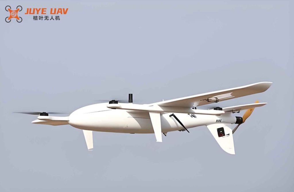
With the rapid advancement of aeronautical technology, fixed‑wing UAVs are increasingly deployed in military, civilian, industrial, agricultural, and exploration missions. The V‑tail offers advantages over conventional Y‑ or T‑tails in terms of aerodynamic performance, flight stability, and structural simplicity. Because of its relatively low weight, the V‑tail is especially preferred for long‑endurance fixed‑wing UAVs. Nevertheless, only limited research has addressed the structural optimization of V‑tails for fixed‑wing UAVs, and most existing studies rely solely on static or modal analysis, overlooking potential changes in aerodynamic behavior after optimization. This work aims to fill that gap by employing response surface methodology (RSM) to achieve a lightweight V‑tail for a fixed‑wing UAV without compromising its aerodynamic performance. The approach integrates finite element analysis (FEA) for structural verification and computational fluid dynamics (CFD) for flow field evaluation.
Model Establishment and Material Selection
V‑Tail Structure
The V‑tail is designed as a double‑spar structure, a typical configuration in which the spars carry most of the loads while the skin and ribs transfer forces to the spars. The symmetric airfoil NACA 0012 is chosen because of its well‑known characteristics and common use in UAV tail surfaces.
Overall Geometric Parameters
Based on engineering experience and existing fixed‑wing UAV designs, the initial V‑tail wingspan is set to 2.13 m, aspect ratio to 4.02, chord length to 0.53 m, and sweep angle to 4.27°. The tip‑to‑root chord ratio is 0.7. Table 1 summarizes the geometric parameters.
| Parameter | Value |
|---|---|
| Wingspan (m) | 2.13 |
| Chord length (m) | 0.53 |
| Aspect ratio | 4.02 |
| Sweep angle (°) | 4.27 |
Material Properties
The V‑tail is made of epoxy‑carbon‑fiber composite, which offers superior specific strength and stiffness. Table 2 lists the mechanical properties used in the FEA.
| Property | Value |
|---|---|
| Density (kg/mm³) | 1.518 × 10⁶ |
| Elastic modulus X (MPa) | 1.233 × 10⁵ |
| Elastic modulus Y (MPa) | 7 780 |
| Elastic modulus Z (MPa) | 7 780 |
| Poisson ratio XY | 0.27 |
| Poisson ratio YZ | 0.42 |
| Poisson ratio XZ | 0.27 |
| Shear modulus XY (MPa) | 5 000 |
| Shear modulus YZ (MPa) | 3 080 |
| Shear modulus XZ (MPa) | 5 000 |
Static Analysis of the Initial V‑Tail
A finite element model of the V‑tail is created with tetrahedral elements (element size 20 mm), yielding 112 429 nodes and 58 420 elements. A distributed pressure of 0.003 MPa is applied to the stabilizer skin to simulate the critical roll‑recovery load case. The V‑tail root is fixed as a cantilever boundary condition.
The static analysis shows a maximum deformation of 46.284 mm at the tip, which is below the allowable limit of 53.25 mm (2.5 % of the span). The maximum von Mises stress is 101.85 MPa, well below the material’s allowable stress.
Response‑Surface‑Based Lightweight Optimization
Design Variables and Objective
To reduce the number of design variables while capturing the main structural effects, three parameters are selected: wingspan (1530–2130 mm, step 100 mm), number of ribs (16–22, step 1), and skin thickness (1.5–2.1 mm, continuous). The objective is to minimize the structural mass, subject to the constraint that the maximum deformation does not exceed 2.5 % of the wingspan.
Response Surface Generation
A central composite design (CCD) is employed, producing 7 × 7 × 5 = 245 experimental runs. Each combination is evaluated via a coupled SolidWorks → ANSYS simulation. A genetic‑algorithm‑based response surface is then fitted. Figure 1 shows the response surfaces for the mass and displacement as functions of the variables.
Optimization Results
Three candidate points are obtained, as listed in Table 3. The configuration with the lowest mass (24.784 kg) is selected: wingspan = 1730 mm, number of ribs = 17, skin thickness = 1.55 mm. This represents a mass reduction of 22.88 % from the initial 32.138 kg.
| Parameter | Candidate 1 | Candidate 2 | Candidate 3 |
|---|---|---|---|
| Wingspan (mm) | 1730 | 1730 | 1730 |
| Number of ribs | 17 | 18 | 17 |
| Skin thickness (mm) | 1.5233 | 1.5293 | 1.5402 |
| Max displacement (mm) | 43.248 | 43.047 | 42.993 |
| Mass (kg) | 24.721 | 24.993 | 24.764 |
| Max stress (MPa) | 105.81 | 106.09 | 105.36 |
Validation Static Analysis
The optimized model is re‑analyzed under the same loading and boundary conditions. The maximum deformation is 42.85 mm (below the limit of 43.25 mm) and the maximum stress is 106.93 MPa, both satisfying design requirements.
Modal Analysis
Modal analysis is performed on both the initial and optimized V‑tails with a fixed root boundary condition. The first six natural frequencies are listed in Table 4. The frequencies of the optimized structure are higher due to reduced dimensions. The excitation frequency of a typical five‑blade propeller used on the fixed‑wing UAV is in the range of 200–250 Hz. Since all modal frequencies are well below this range, resonance is avoided.
| Mode | Initial | Optimized |
|---|---|---|
| 1 | 5.707 | 8.572 |
| 2 | 29.514 | 43.051 |
| 3 | 34.326 | 48.566 |
| 4 | 41.936 | 53.601 |
| 5 | 68.405 | 101.510 |
| 6 | 101.270 | 138.650 |
External Flow Field Simulation
Setup
A full‑scale fixed‑wing UAV model is built with both the initial and optimized V‑tails. The computational domain is 15 m × 5 m × 3 m. A poly‑hexcore mesh with local refinement near the UAV surface is used. The inlet velocity corresponds to typical cruise conditions for a large fixed‑wing UAV.
Aerodynamic Performance Comparison
The pressure contours, velocity vectors, and streamlines are compared. The overall flow patterns are very similar between the two configurations. The maximum pressure on the UAV decreases from 2890 Pa to 2860 Pa after optimization, and the maximum surface velocity reduces from 112 m/s to 110 m/s, indicating a slight improvement in drag.
Quantitative results are extracted for a range of Reynolds numbers. The drag force is reduced by an average of about 6 N (0.75 % of initial drag), with a maximum reduction of 7.4 N. The pitching moment decreases by about 147 N·m (21.8 %). The lift force drops by approximately 800 N (7.68 %), and the lift‑to‑drag ratio decreases by about 0.85 (6.5 %). Despite these changes, the lift‑to‑drag ratio remains within the typical range of 9‑14 for fixed‑wing UAVs, confirming that the aerodynamic performance is not significantly compromised.
FDM Additive Manufacturing Validation
To physically verify the mass reduction, scaled models (10 % of full size) of both the initial and optimized V‑tails are manufactured using FDM with photopolymer resin (Makerbot METHOD X). The printing parameters are: 100 % infill, 15 % support density, 30 mm/s outer contour speed, and 50 mm/s internal speed.
The initial prototype weighs 43.3 g, while the optimized one weighs 33.3 g, a reduction of 23.09 %. This value closely matches the simulated mass reduction of 22.88 %, with a discrepancy of only 0.21 %, demonstrating the reliability of the optimization approach.
Conclusion
This study presents a comprehensive lightweight design of a V‑tail for a fixed‑wing UAV using response surface methodology. The following conclusions are drawn:
- The optimized V‑tail achieves a mass reduction of 22.88 % (from 32.138 kg to 24.784 kg) while meeting strength and deformation requirements under critical roll‑recovery loads.
- Modal analysis confirms that the natural frequencies of the optimized structure avoid the propeller excitation band, ensuring no resonance.
- External flow field simulations show that the aerodynamic performance of the fixed‑wing UAV remains essentially stable. The drag and moment decrease by 0.75 % and 21.8 %, respectively, while the lift and lift‑to‑drag ratio drop by 7.68 % and 6.5 %, still within acceptable limits for long‑endurance fixed‑wing UAVs.
- FDM prototyping validates the simulated mass reduction, with a measured weight decrease of 23.09 % vs. 22.88 % predicted.
The proposed design methodology effectively balances structural lightweighting and aerodynamic stability, offering a practical solution for improving the endurance of fixed‑wing UAVs.