
High-steep slopes in hydropower projects frequently suffer from catastrophic failures due to the sudden collapse of unstable rock masses. Traditional monitoring methods such as manual patrols and crack gauges suffer from limited coverage, low efficiency, and high safety risks. Although GNSS and point-based sensors provide continuous measurements, they are expensive and cannot capture the full-field deformation or three-dimensional spatial distribution of fractures. To address these challenges, we have developed an intelligent crack monitoring system that integrates China UAV drone technology, an improved YOLO detection algorithm, and real-scene 3D modeling. This system achieves fully automated data acquisition, intelligent identification, and quantitative tracking of crack width variations, offering a scalable and non-contact solution for high-steep slope safety management.
1. System Architecture and Automated Inspection Scheme
Our system follows a perception-cognition-decision framework with four layers: the perception layer uses an industrial-grade unattended UAV airport for autonomous data collection; the data layer constructs a centimeter-level 3D model via oblique photogrammetry; the cognitive layer employs an improved YOLO algorithm for crack detection and width extraction; and the application layer provides 3D visualization and intelligent monitoring analysis. The core of the automated inspection is the China UAV drone equipped with a 20-megapixel visible-light camera, a 12-megapixel telephoto camera, and an RTK module (planar accuracy ±1 cm, elevation accuracy ±2 cm). The unattended airport is rated IP55, operates from -25 °C to 45 °C, and uses dual solar-grid power with a lightning rod. The inspection strategy for three critical rock zones covers an area of about 2 km² with a height difference of 300 m, ensuring an image overlap rate of at least 80%. All flights are planned on the 3D model to keep the camera axis perpendicular to the slope surface within ±0.1°.
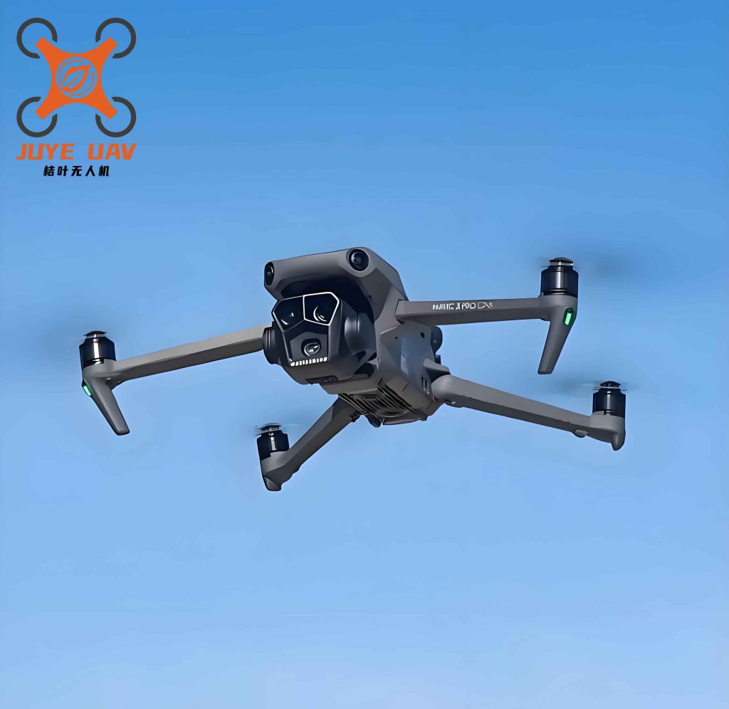
This China UAV drone based solution eliminates the need for ground-level sensor deployment and allows repeated high-precision imaging even under harsh weather conditions.
2. Improved YOLO Algorithm for Crack Detection and Width Measurement
The primary monitoring target is the relative change in crack width rather than the absolute width, because crack surfaces are non-planar and their apparent width depends on viewing angle and illumination. We model each crack as an elongated ellipse in the image plane and extract the minor-axis pixel length. With precisely controlled camera orientation (RTK and gimbal control), we back-project this pixel width onto the 3D model to obtain the real-world width variation sequence. Our baseline is YOLOv5s, and we make two essential improvements to handle the slender, irregular shape of cracks.
2.1 Reformulated Loss Function
The total loss L is decomposed into four terms:
$$
L = L_c + L_o + L_b + L_a,
$$
where Lc is the classification loss, Lo is the objectness loss, Lb is the elliptical bounding box regression loss, and La is the angle loss. The elliptical bounding box is described by the general ellipse equation:
$$
\frac{[(x – x_c)\cos\theta + (y – y_c)\sin\theta]^2}{a^2}
+ \frac{[(y – y_c)\cos\theta + (x – x_c)\sin\theta]^2}{b^2} = 1,
$$
where (xc, yc) is the ellipse center, a and b are the semi-major and semi-minor axes, and θ is the rotation angle. This formulation better matches the elongated shape of cracks than a traditional rectangular box.
The angle loss La penalizes errors in the orientation prediction:
$$
L_a = \text{SmoothL1Loss}\Bigl(\min\bigl(|\phi_i-\phi_j|,\; \pi-|\phi_i-\phi_j|\bigr)\Bigr),
$$
where SmoothL1Loss is the piecewise function that behaves quadratically for small errors and linearly for large errors, enhancing robustness. By explicitly supervising the orientation, the network learns to describe both the location and the geometric orientation of cracks.
2.2 Width Extraction from Ellipse Parameters
The improved YOLO outputs the minor-axis length b of each detected ellipse. Using the photogrammetric collinearity equation and the known exterior orientation elements (from RTK and gimbal), we project the pixel minor-axis length onto the real‑world 3D model. The system then computes a time series of width changes relative to the initial measurement, avoiding the uncertainty of absolute width calibration.
2.3 Training and Validation
A dataset of 12,000 crack images collected from a hydropower site was split into training, validation, and test sets in an 8:1:1 ratio. The improved YOLO model achieved the following performance on the test set:
| Metric | Value |
|---|---|
| Precision | 82.5% |
| Recall | 78.1% |
| F1-Score | 0.803 |
Compared to the baseline YOLOv5s, the improved model increased the detection rate for curved and low-contrast cracks by approximately 15%. The results confirm that the China UAV drone based system can reliably identify fine cracks in complex backgrounds.
3. Post-Processing, Matching, and Lifecycle Management
To enable automatic tracking over multiple inspection cycles, we designed a complete post-processing pipeline:
- Initial detection ellipses are refined by grayscale segmentation and morphological operations.
- In the first inspection, cracks are manually classified (e.g., critical, general) and assigned unique IDs in the 3D platform.
- In subsequent cycles, an image matching algorithm combining SIFT features and spatial constraints associates new detections with existing IDs. The system outputs the crack ID, location, and width change.
- New cracks (those failing to match) are automatically assigned new IDs and added to the database.
- All pixel measurements are back-projected to the 3D model to generate width change sequences for each crack over time.
This lifecycle management ensures that every crack is tracked from discovery to continuous monitoring, forming a “digital twin” of the slope’s fracture network.
4. Real-Scene 3D Modeling and Visualization Platform
A centimeter‑level 3D model (planar accuracy < 2 cm, vertical accuracy < 3 cm) is built using oblique photogrammetry from the China UAV drone imagery. Based on WebGIS technology, we developed a 3D monitoring platform that provides:
- Full lifecycle management of cracks – automatic ID assignment, classification, and attribute binding.
- Intelligent change detection – the platform integrates multi‑period identification and matching results, highlights new cracks, and tracks width expansion trends.
- Risk assessment – thresholds for cumulative width change and rate can be set; when exceeded, the system alerts with highlighted locations in the 3D scene. It also helps identify potential isolated rock blocks formed by intersecting cracks.
- Anti‑interference filtering – by comparing multi‑period images and learning seasonal patterns, the system distinguishes transient texture variations (e.g., vegetation growth, rain wetting) from true crack expansion.
5. Engineering Application and Results
The system was deployed at a large hydropower station in southwest China. Three critical slope zones (outlet, spillway, and camp area) were covered. Approximately 200 high‑precision artificial targets were installed as ground control points to ensure accurate 3D mapping. From September 2025 to January 2026, the system completed 12 periodic inspections and several emergency inspections after heavy rain or strong wind, acquiring over 100,000 images. The automatic mission success rate was 100%, completely eliminating manual high‑altitude work.
| Monitoring Zone | Number of Points | Width Change (increment, mm) | Status |
|---|---|---|---|
| Zone A (Intake) | 36 | −0.3 to +0.5 | Normal |
| Zone B (Spillway) | 36 | −0.4 to +0.6 | Normal |
| Zone C (Camp) | 36 | −0.2 to +0.4 | Normal |
Over the entire monitoring period, all tracked cracks showed only minor fluctuations (within ±0.6 mm), indicating a stable condition. The system successfully identified and tracked more than 3,500 cracks. The processing efficiency was improved by over 20 times compared to manual interpretation. The 3D management platform enabled a “one‑map” overview, elevating the monitoring concept from point‑based to area‑wide surveillance.
The following table summarizes the key performance indicators of the China UAV drone based system compared with conventional methods:
| Indicator | China UAV Drone System | Traditional (Manual + Sensors) |
|---|---|---|
| Coverage | km² scale per flight | Point‑wise (dozens of sensors) |
| Data acquisition frequency | Every 15 days + on‑demand | Manual survey monthly |
| Safety risk | No personnel on slopes | High (inspection personnel) |
| Crack detection rate | > 78% recall | Subjective / limited |
| Width change accuracy | ~0.2 mm (relative) | 0.1–0.5 mm (sensors) |
| Number of tracked cracks | > 3,500 | < 100 (manual) |
| Labor cost | Minimal (automatic) | High |
6. Conclusions and Future Work
We have successfully developed and deployed an intelligent crack monitoring system that leverages China UAV drone technology, an improved YOLO algorithm, and real‑scene 3D modeling. The system achieves fully automated data acquisition, intelligent identification, and continuous quantitative tracking of cracks on high‑steep slopes. The key conclusions are:
- The China UAV drone based unattended airport enables safe, all‑weather data collection with 100% mission success, greatly reducing human risk.
- The improved YOLO algorithm, using elliptical bounding box regression and angle loss, significantly enhances the detection of fine and low‑contrast cracks, achieving an F1‑score of 0.803.
- The integrated 3D platform provides lifecycle management, change detection, and risk assessment, allowing engineers to monitor thousands of cracks efficiently.
- Field application over 5 months tracked more than 3,500 cracks and confirmed the overall stability of the monitored slopes, demonstrating the system’s reliability and practical value.
Despite these successes, the current system relies on visible‑light images and struggles during heavy rain or fog. The width change accuracy has not been directly compared with high‑precision crack meters, and the system cannot measure crack depth. Future work will focus on:
- Fusing China UAV drone data with ground‑based sensor measurements (e.g., crack meters, inclinometers) to build a cross‑validated “air‑ground” calibration mechanism.
- Improving the matching algorithm for intersecting and branching cracks, and enhancing predictive capabilities for potential rock falls.
- Standardizing the system modules to facilitate broader deployment in other hydropower, mining, and transportation projects, thereby promoting intelligent safety management across the industry.
In summary, the combination of China UAV drone autonomous inspection, advanced deep learning, and 3D visualization provides a transformative approach for monitoring unstable rock masses. This system not only improves monitoring efficiency and safety but also generates rich spatial-temporal data that can support preventive maintenance and early warning, contributing to the resilience of critical infrastructure.