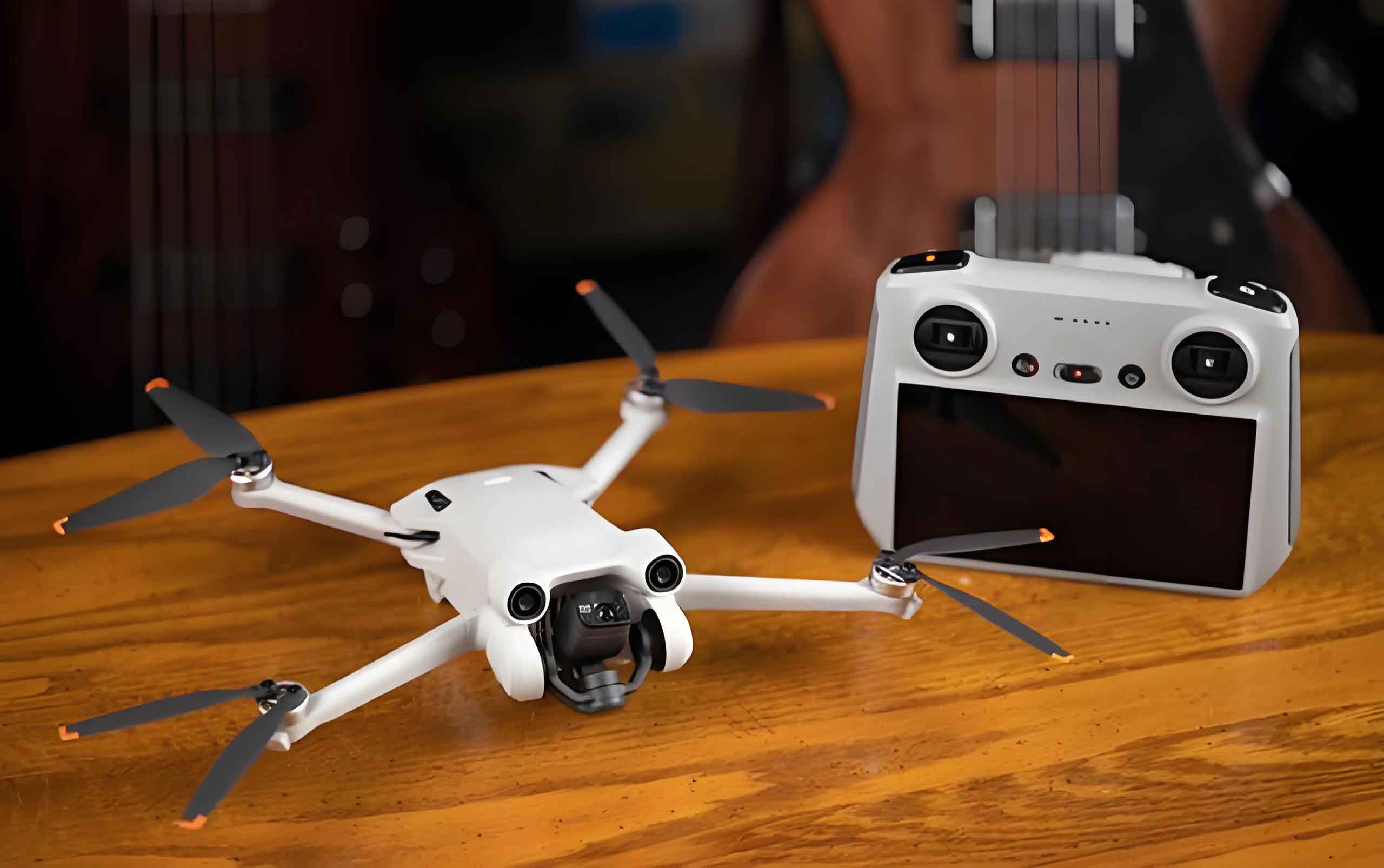
In modern battlefield environments, drone technology has become increasingly vital due to its cost-effectiveness and operational versatility. However, the susceptibility of small fixed-wing drones to external electromagnetic interference poses a critical challenge to flight stability. Our study investigates the continuous-wave electromagnetic radiation effects on such drones, focusing on the field-to-line coupling mechanism that leads to servo jitter. By combining simulation and experimental methods, we reveal how electromagnetic energy couples into internal cables, particularly the servo signal lines, and disrupts the pulse width modulation (PWM) control signals.
Our research establishes a comprehensive field-to-line coupling model for small fixed-wing drones using CST electromagnetic simulation software. The model incorporates the physical structure of the drone, including the fuselage, wings, tail, and internal cable routing. Five typical cable types are identified: the servo signal lines for rudder and elevator (C1), coaxial data link cable (C2), three-phase motor power lines (C3), coaxial GPS antenna feed (C4), and power supply cable (C5). The physical parameters of each cable are measured and listed in Table 1.
| Cable Type | Length (Rudder/Elevator) | Conductor Radius (r1) | Insulator Outer Radius (r2) | Outer Conductor Radius (r3) | Jacket Outer Radius (r4) |
|---|---|---|---|---|---|
| C1 (Rudder) | 620.4 | 0.4 | 0.6 | − | − |
| C1 (Elevator) | 815.6 | 0.4 | 0.6 | − | − |
| C2 (Data link) | 216.7 | 0.5 | 0.84 | 1.0 | 1.5 |
| C3 (Motor) | 230.9 | 0.5 | 1.2 | − | 1.8 |
| C4 (GPS) | 226.0 | 0.5 | 0.84 | 1.0 | 1.5 |
| C5 (Power) | 64.7 | 1.0 | 1.5 | − | − |
The drone model was constructed in SolidWorks and imported into CST. Material properties were assigned: the bottom plate, brushless motor, and gimbal housing were set as magnesium-aluminum alloy (conductivity 2.76e7 S/m), while other structures were dielectric (relative permittivity εr=4.3, relative permeability μ=1). Cables were loaded in CST Cable Studio according to actual routing. The incident plane wave parameters were defined with elevation angle θ, azimuth angle φ, and polarization angle α. Four typical irradiation scenarios were simulated: horizontal polarization (α=0°) and vertical polarization (α=90°) from the nose (φ=180°) and from the left fuselage side (φ=270°). The electric field expression is:
$$ \mathbf{E}(x,y,z) = E(t)(e_x \hat{a}_x + e_y \hat{a}_y + e_z \hat{a}_z)e^{-j(k_x x + k_y y + k_z z)} $$
where the components are given by:
$$ \begin{aligned}
e_x &= -\cos\phi \cos\theta \sin\alpha – \sin\phi \cos\alpha \\
e_y &= -\sin\phi \cos\theta \sin\alpha + \cos\phi \cos\alpha \\
e_z &= \sin\theta \sin\alpha
\end{aligned} $$
$$ \begin{aligned}
k_x &= -k \sin\theta \cos\phi \\
k_y &= -k \sin\theta \sin\phi \\
k_z &= -k \cos\theta
\end{aligned} $$
and $$k = 2\pi/\lambda$$ is the wavenumber in free space.
The excitation signal was a Gaussian pulse covering 0–500 MHz, with a peak field strength set to 100 V/m. All cable ports were terminated with 50 Ω loads to ground. Voltage probes were placed at the terminals of each cable near the flight controller or servos to record coupled voltages. Our simulation results, summarized in Figure 6 of the original paper (not reproduced here to avoid image numbers), showed that the rudder servo signal line (C1-rudder) exhibited the highest coupled voltage among all cables under all four scenarios. Horizontal polarization from the fuselage side produced the maximum coupled voltage of 7.74 V on the rudder signal line at the resonance frequency around 181 MHz, while vertical polarization yielded 4.61 V. The elevator signal line (C1-elevator) also showed strong coupling, with resonant peaks at approximately 172 MHz and 129 MHz depending on polarization. Coaxial cables (C2 and C4) had very low coupled voltages (below 0.46 V) due to shielding. The motor power lines (C3) peaked at 1.13 V under horizontal polarization, still well below the operating voltage threshold. These findings confirm that the servo signal lines are the most sensitive field-to-line coupling paths in the drone technology context.
To validate the simulation, we conducted continuous-wave irradiation experiments in a microwave anechoic chamber. The drone was placed at a height of 1.2 m, 2 m from the transmitting antenna. A vector signal generator, power amplifier, and horn antenna generated the continuous wave field. A GPS signal simulator provided navigation signals, while a ground control station monitored the telemetry data. High-speed cameras recorded tail motion. Two polarizations (horizontal and vertical) and two incidence directions (nose and left fuselage side) were tested across 30–500 MHz. The key experimental observation was tail fin jitter (non-command oscillation) as a typical back-door coupling effect. Sensitive frequency bands were identified where jitter appeared at relatively low field thresholds. The results are shown in Table 2.
| Frequency Range (MHz) | Field Strength Threshold (V/m) | Observed Effect |
|---|---|---|
| 30–100 | − (no effect) | None |
| 101–250 | 52.6 (minimum) | Non-command tail jitter; vertical tail jitters first |
| 251–350 | 80.2 | Tail jitter plus pitch and roll angle reading fluctuations |
| 351–400 | 146.3 | Pitch and roll angle reading fluctuations only |
| 401–500 | − (no effect) | None |
Figure 8 in the original paper (not shown) indicates that the field threshold curves exhibit a “V-shaped” pattern around three center frequencies: 165 MHz, 241 MHz, and 337 MHz. These frequencies are almost independent of polarization and incidence angle, suggesting they are intrinsic resonances of the internal cable structure. The lowest threshold of 52.6 V/m occurred for horizontal polarization with left fuselage incidence. This aligns perfectly with the half-wavelength resonance condition for the rudder servo signal line (length 620.4 mm) in a dielectric medium. The resonance frequency is given by:
$$ f_w = \frac{nv}{2L} = \frac{nc}{2L\sqrt{\varepsilon_r}} $$
where L is the cable length, c is the speed of light, εr = 2.2 is the relative permittivity of the cable insulation, and n = 1,2,3,… For the rudder line (L=0.6204 m), the first three half-wavelength resonances are approximately 163 MHz, 248 MHz, and 326 MHz. A comparison between theoretical, simulated, and experimental sensitive frequencies is given in Table 3.
| Mode | Theoretical (MHz) | Simulated (MHz) | Experimental (MHz) |
|---|---|---|---|
| n=1 | 163 | 172 (deviation 5%) | 165 (deviation 1.2%) |
| n=2 | 248 | 261 (deviation 5.2%) | 241 (deviation 2.8%) |
| n=3 | 326 | 336 (deviation 3%) | 337 (deviation 3.4%) |
The close agreement confirms that the tail jitter originates from field-to-line coupling into the servo signal cables, rather than from front-door coupling through antennas or sensor interference. To further understand the mechanism, we analyzed the time-domain behavior of the tail deflection. Under 150 MHz, 100 V/m vertical polarization irradiation, the vertical fin deflection was recorded. The motion was high-frequency, non-periodic, and random, with no relation to the flight controller’s 10 Hz attitude update cycle. This rules out sensor-induced error and points directly to the servo control circuit being disrupted by induced common-mode currents.
The mechanism can be explained as follows: when the incident continuous wave resonates with the servo signal cable, a significant common-mode current Icm flows along the cable. Because the three-wire twisted bundle (signal, ground, power) is not perfectly balanced, and the input impedance of the servo controller’s PCB is slightly asymmetric, the common-mode current is partially converted into a differential-mode voltage ΔVdm across the signal and ground terminals:
$$ \Delta V_{dm} = I_{cm} \cdot Z_{unbalance} $$
where Z_unbalance is the unbalanced impedance. This differential noise voltage is superimposed on the PWM signal that controls the servo position. The servo’s internal comparator interprets the distorted pulse width as an erroneous position command. As the field strength increases, Icm increases, leading to larger ΔVdm and consequently greater jitter amplitude, consistent with our experimental observation of continuous amplitude growth with field strength.
Our findings provide a clear picture of the field-to-line coupling interference mechanism in drone technology. The servo signal cable acts as an efficient receiving antenna at its half-wavelength resonance frequencies, converting external electromagnetic energy into common-mode currents, which then transform into differential-mode voltage perturbations on the PWM control signal, causing the tail to jitter. The sensitive frequencies are determined by the cable length and dielectric constant, and the coupling efficiency is highest when the electric field is parallel to the cable axis (horizontal polarization) and the incidence is from the side of the fuselage. These insights are crucial for designing effective electromagnetic protection measures for small fixed-wing drones, such as using shielded twisted pairs, ferrite chokes, or optimizing cable routing to avoid resonance.
In conclusion, our study systematically reveals the field-to-line coupling mechanism of continuous-wave electromagnetic radiation on small fixed-wing drones through simulation and experiment. The servo signal line is identified as the primary back-door coupling path, with resonance frequencies around 165 MHz, 241 MHz, and 337 MHz. The lowest interference threshold is 52.6 V/m under horizontal polarization from the side. The mechanism involves common-mode current conversion to differential-mode voltage, which disrupts the PWM signal and causes non-command tail jitter. These results contribute to the understanding of electromagnetic vulnerability of drone technology and provide a foundation for developing effective hardening strategies.