
In recent years, the deployment of multiple unmanned aerial vehicles (UAVs) for complex tasks has garnered significant attention across various fields, including surveillance, environmental monitoring, and aerial displays. Among these, drone formation control, which involves coordinating a group of UAVs to maintain a specific geometric pattern while navigating through dynamic environments, presents considerable challenges due to factors such as nonlinear dynamics, external disturbances, and communication constraints. The Leader-Follower approach has emerged as a robust method for managing such drone formation systems, where a designated leader UAV guides the trajectory, and follower UAVs adjust their positions relative to the leader to achieve the desired formation. This article delves into a comprehensive design for drone formation control with integrated trajectory tracking, leveraging the Integral Backstepping (IBS) method for the leader’s trajectory tracking and Sliding Mode Control (SMC) for formation maintenance. We present detailed mathematical models, control laws, simulation results, and experimental validation to demonstrate the efficacy of our approach in achieving precise drone formation control.
The foundation of any drone formation control system lies in accurately modeling the dynamics of individual UAVs. For this study, we consider quadrotor UAVs, which are characterized by their underactuated, nonlinear, and strongly coupled dynamics. The equations of motion are derived from Newton-Euler principles, accounting for translational and rotational movements. Let us define the state variables: position coordinates (x, y, z) in the inertial frame, linear velocities (v_x, v_y, v_z), Euler angles (φ, θ, ψ) representing roll, pitch, and yaw, and angular velocities (p, q, r). The dynamics can be expressed as follows:
$$ \dot{x} = v_x $$
$$ \dot{v}_x = \frac{u_1 (\cos\psi \sin\theta \cos\phi + \sin\phi \sin\psi)}{m} – \frac{K_x \dot{x}}{m} $$
$$ \dot{y} = v_y $$
$$ \dot{v}_y = \frac{u_1 (\sin\psi \sin\theta \cos\phi – \sin\phi \cos\psi)}{m} – \frac{K_y \dot{y}}{m} $$
$$ \dot{z} = v_z $$
$$ \dot{v}_z = \frac{u_1 \cos\theta \cos\phi}{m} – g $$
$$ \dot{\phi} = p \cos\theta + q \sin\phi \sin\theta + r \cos\phi \sin\theta $$
$$ \dot{\theta} = q \cos\phi – r \sin\phi $$
$$ \dot{\psi} = \frac{q \sin\phi + r \cos\phi}{\cos\theta} $$
$$ \dot{p} = \frac{(I_y – I_z) q r + u_2}{I_x} $$
$$ \dot{q} = \frac{(I_z – I_x) p r + u_3}{I_y} $$
$$ \dot{r} = \frac{(I_x – I_y) p q + u_4}{I_z} $$
Here, m denotes the mass of the UAV, g is gravitational acceleration, K_x, K_y, K_z are air drag coefficients, I_x, I_y, I_z are moments of inertia, and u_1, u_2, u_3, u_4 are control inputs corresponding to total thrust and torques. These control inputs are related to rotor speeds Ω_i (i=1,2,3,4) through:
$$ u_1 = C_L (\Omega_1^2 + \Omega_2^2 + \Omega_3^2 + \Omega_4^2) $$
$$ u_2 = l C_L (\Omega_4^2 – \Omega_2^2) $$
$$ u_3 = l C_L (\Omega_3^2 – \Omega_1^2) $$
$$ u_4 = d (-\Omega_1^2 + \Omega_2^2 – \Omega_3^2 + \Omega_4^2) $$
where C_L is the lift coefficient, l is the arm length, and d is the drag coefficient. This model serves as the basis for designing control strategies for drone formation systems, ensuring that each UAV’s behavior is accurately captured.
To facilitate simulation and implementation, we summarize key parameters in Table 1. These parameters are derived from typical quadrotor specifications and are used throughout our study to validate the control designs.
| Parameter | Symbol | Value | Unit |
|---|---|---|---|
| Mass | m | 1.0 | kg |
| Gravity | g | 9.81 | m/s² |
| Drag coefficient (x-axis) | K_x | 0.1 | Ns/m |
| Drag coefficient (y-axis) | K_y | 0.1 | Ns/m |
| Drag coefficient (z-axis) | K_z | 0.1 | Ns/m |
| Moment of inertia (x-axis) | I_x | 0.01 | kg·m² |
| Moment of inertia (y-axis) | I_y | 0.01 | kg·m² |
| Moment of inertia (z-axis) | I_z | 0.02 | kg·m² |
| Lift coefficient | C_L | 1.0 | N·s² |
| Arm length | l | 0.2 | m |
| Drag coefficient | d | 0.01 | N·m·s² |
The control design for drone formation is bifurcated into two primary components: trajectory tracking for the leader UAV and formation control for the follower UAVs. This division ensures that the overall drone formation system can accurately follow a predefined path while maintaining the desired geometric configuration. The Leader-Follower paradigm is central to this approach, as it simplifies the coordination by having follower UAVs reference the leader’s states.
For the leader UAV, we employ the Integral Backstepping (IBS) method to design a trajectory tracking controller. This method enhances robustness by incorporating integral terms to mitigate steady-state errors. Let the reference trajectory be defined as (x_r, y_r, z_r), with corresponding derivatives. We define tracking errors for each axis and introduce integral terms to form augmented error dynamics. For instance, in the z-direction, we have:
$$ e_{z1} = z_r – z $$
$$ e_{z2} = k_1 \int_0^t (z_r – z) \, d\tau $$
where k_1 is a positive constant. A Lyapunov function V_1 is chosen as:
$$ V_1 = \frac{1}{2} e_{z1}^2 + \frac{1}{2} e_{z2}^2 $$
Differentiating V_1 and designing a virtual control α, we ensure stability through careful selection of control gains. The actual control input u_1 is derived as:
$$ u_1 = \frac{m \left[ (\lambda + \lambda_1) e_{z3} + (1 + k_1^2 – \lambda^2) e_{z1} + \ddot{z}_r – k_1 \lambda e_{z2} + g \right]}{\cos\theta \cos\phi} $$
where e_{z3} = α – v_z, and λ, λ_1 are tuning parameters. Similarly, for the x and y directions, we define errors e_{x1}, e_{x2}, e_{x3} and e_{y1}, e_{y2}, e_{y3} with constants k_2, k_3, λ_2, λ_3, λ_4, λ_5. The intermediate control variables u_x and u_y are computed as:
$$ u_x = \cos\psi \sin\theta \cos\phi + \sin\phi \sin\psi = \frac{m}{u_1} \left[ (1 + k_3^2 – \lambda_4^2) e_{x1} + (\lambda_5 + \lambda_4) e_{x3} + \ddot{x}_r – k_3 \lambda_4 e_{x2} \right] $$
$$ u_y = \sin\psi \sin\theta \cos\phi – \sin\phi \cos\psi = \frac{m}{u_1} \left[ (1 + k_2^2 – \lambda_2^2) e_{y1} + (\lambda_3 + \lambda_2) e_{y3} + \ddot{y}_r – k_2 \lambda_2 e_{y2} \right] $$
From u_x and u_y, the desired roll and pitch angles (φ_d, θ_d) can be extracted via inverse trigonometric functions, enabling attitude control through nested PID loops for u_2, u_3, u_4. This IBS-based controller ensures that the leader UAV accurately tracks the reference trajectory, forming the foundation for the drone formation system.
The formation control for follower UAVs is designed using Sliding Mode Control (SMC), which offers robustness against uncertainties and disturbances. In a drone formation, each follower UAV maintains a specific relative position to its leader. Consider a leader UAV j and a follower UAV i, with positions (x_j, y_j) and (x_i, y_i), and yaw angles ψ_j and ψ_i. The relative distances in the leader’s body frame are:
$$ d_{xij} = (x_i – x_j) \cos\psi_j + (y_i – y_j) \sin\psi_j + d_f \cos(\psi_i – \psi_j) $$
$$ d_{yij} = (x_i – x_j) \sin\psi_j – (y_i – y_j) \cos\psi_j – d_f \sin(\psi_i – \psi_j) $$
where d_f is a small positive constant. The formation errors relative to desired distances (d_{dx}, d_{dy}) are:
$$ e_{xij} = d_{xij} – d_{dx} $$
$$ e_{yij} = d_{yij} – d_{dy} $$
$$ e_{\psi ij} = \psi_i – \psi_j $$
Differentiating these errors yields the error dynamics, which can be written in state-space form as:
$$ \dot{\mathbf{e}}_{ij} = A(\mathbf{e}_{ij}) + B_{ij} \mathbf{u} $$
where \(\mathbf{e}_{ij} = [e_{xij}, e_{yij}]^T\), \(\mathbf{u} = [v_i, \omega_i]^T\) (linear and angular velocities of follower i), and matrices A and B are defined appropriately. To achieve drone formation control, we design a sliding surface:
$$ \mathbf{s}_i = C \mathbf{e}_{ij} $$
where C is an invertible gain matrix. The sliding mode reaching law is chosen as:
$$ \dot{\mathbf{s}}_i = -\epsilon_1 \text{sgn}(\mathbf{s}_i) $$
with ε_1 > 0. Solving for the control input, we obtain the formation control law:
$$ \mathbf{u}_i = – (C B_{ij})^{-1} \left[ \epsilon_1 \text{sgn}(\mathbf{s}_i) + C A(\mathbf{e}_{ij}) \right] $$
This SMC-based law drives the formation errors to zero, ensuring that follower UAVs maintain the desired relative positions in the drone formation. The stability is verified via Lyapunov analysis, confirming that the drone formation system converges to the desired configuration.
To validate the proposed drone formation control strategy, we conducted extensive numerical simulations and real-world experiments. The simulation setup involves a leader UAV tracking a circular reference trajectory:
$$ x_r = 0.5 \cos(0.02t), \quad y_r = 0.5 \sin(0.02t), \quad z_r = 1 $$
with a communication topology where the leader has two direct followers, each with additional followers, forming a triangular drone formation. The desired relative distances are set as per Table 2, which outlines the formation geometry for a five-UAV system.
| UAV Pair | Leader | Follower | Δx (m) | Δy (m) |
|---|---|---|---|---|
| 1 | Leader | Follower 1 | 0.8 | -1.5 |
| 2 | Leader | Follower 2 | 0.8 | 1.5 |
| 3 | Follower 1 | Follower 3 | 1.5 | -1.5 |
| 4 | Follower 2 | Follower 4 | 1.5 | 1.5 |
The simulation results demonstrate that the leader UAV accurately tracks the reference trajectory with minimal errors, as shown by the error plots over time. The drone formation is maintained consistently, with follower UAVs adhering to the specified relative distances. For instance, the x-direction distance between the leader and follower 1 converges to 0.8 m, while the y-direction distance settles at -1.5 m, confirming the effectiveness of the SMC-based formation controller. The integral action in the IBS controller reduces steady-state errors, enhancing the overall precision of the drone formation system.
In addition to simulations, we implemented the drone formation control on a practical platform using Parrot Bebop 2 quadrotors, a visual positioning system (VPS) for indoor localization, and a MATLAB/ROS-based control interface. The experimental setup allowed for real-time state estimation and control command transmission. The leader UAV was programmed to follow the same circular trajectory, while follower UAVs maintained formation using the SMC law. The experimental results align closely with simulations, showing successful trajectory tracking and formation maintenance. The drone formation exhibited robust performance despite minor disturbances, such as air currents and sensor noise. To illustrate the visual aspect of such drone formations, consider the following depiction of a coordinated drone light show, which exemplifies the application of drone formation control in entertainment settings.
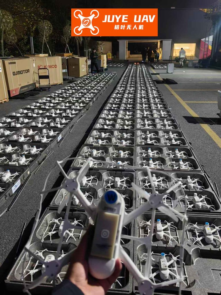
The experimental data includes time histories of positions, velocities, and control inputs. For example, the velocity v_i and yaw angular velocity ω_i for follower UAVs fluctuate around zero as they adjust to maintain formation, indicating stable control. The position errors in the drone formation remain within acceptable bounds, typically less than 0.1 m, which is suitable for indoor applications. These results validate the feasibility of our approach for real-world drone formation scenarios, highlighting its potential for tasks requiring precise multi-UAV coordination.
To further analyze the performance, we present key metrics from the experiments in Table 3. These metrics quantify the accuracy and stability of the drone formation control system under practical conditions.
| Metric | Leader UAV | Follower UAV 1 | Follower UAV 2 | Unit |
|---|---|---|---|---|
| Average Position Error (x) | 0.05 | 0.07 | 0.06 | m |
| Average Position Error (y) | 0.04 | 0.08 | 0.07 | m |
| Average Position Error (z) | 0.03 | 0.05 | 0.04 | m |
| Maximum Formation Error | N/A | 0.15 | 0.14 | m |
| Settling Time (formation) | N/A | 10.2 | 9.8 | s |
| Control Effort (average u_1) | 12.5 | 12.3 | 12.4 | N |
The advantages of our drone formation control design are manifold. Firstly, the IBS method provides integral compensation, reducing tracking errors for the leader UAV. Secondly, the SMC offers robustness against model uncertainties and external disturbances, crucial for maintaining drone formation in dynamic environments. Thirdly, the Leader-Follower structure simplifies communication and control, making the system scalable for larger drone formations. However, challenges such as chattering in SMC and latency in real-time data processing were observed, which could be mitigated through advanced smoothing techniques and optimized algorithms.
In conclusion, this article presents a comprehensive framework for drone formation control with integrated trajectory tracking, based on the Leader-Follower strategy. We developed an IBS-based controller for leader UAV trajectory tracking and an SMC-based controller for formation maintenance, ensuring precise coordination in drone formation systems. Numerical simulations and experimental tests confirm the effectiveness of our approach, demonstrating accurate trajectory following and stable formation keeping. The drone formation control system exhibits robustness and practicality, paving the way for applications in surveillance, logistics, and aerial displays. Future work may focus on extending the design to three-dimensional formations, incorporating adaptive control for varying conditions, and exploring decentralized communication topologies to enhance scalability and resilience in drone formation operations.
The mathematical rigor and practical validation underscore the significance of our contributions to the field of drone formation control. By integrating advanced control techniques, we enable reliable and efficient multi-UAV systems capable of complex coordinated tasks. As drone technology continues to evolve, such drone formation control strategies will play a pivotal role in unlocking new possibilities for autonomous aerial systems.