
The advent of Unmanned Aerial Vehicle (UAV) technology has revolutionized the field of geomatics, particularly in complex and hazardous environments like metal and other hard-rock mines. I have witnessed firsthand the transformative power of drone-based real-scene 3D modeling in shifting mining operations from traditional, labor-intensive surveying methods towards intelligent, data-driven planning and management. This technology integrates advanced flight platforms, sophisticated sensors, and powerful processing algorithms to create highly accurate, photorealistic digital twins of mining landscapes. The application transcends simple mapping; it provides a dynamic, measurable, and analyzable spatial framework that is indispensable for modern, efficient, and safe mining operations. In this analysis, I will delve into the technical architecture of these systems, rigorously examine the factors influencing model accuracy, and propose comprehensive strategies—with a significant emphasis on drone training—to solidify its role as a cornerstone of intelligent mine surveying and planning.
Architectural Framework of a UAV Real-Scene 3D Modeling System
Implementing an effective drone-based 3D modeling solution requires a synergistic integration of several critical subsystems. Each component must be selected and calibrated for the demanding conditions of a mining site.
1. The Aerial Platform and Payload Subsystem: This is the physical workhorse. For mining applications, robustness, stability, and payload capacity are paramount. Fixed-wing UAVs offer superior endurance for covering vast, open-pit areas, while multi-rotor systems provide the vertical take-off, landing, and hovering capabilities essential for detailed scanning of stockpiles, pit walls, and infrastructure. The payload is typically a multi-lens oblique photogrammetry camera system or a LiDAR (Light Detection and Ranging) sensor. The camera system captures high-resolution, geotagged imagery from multiple angles (nadir and oblique), which is crucial for reconstructing the vertical faces of benches and structures. The geometric relationship between image points and ground points is foundational, often described by the collinearity equations:
$$ x – x_0 = -f \frac{m_{11}(X – X_0) + m_{12}(Y – Y_0) + m_{13}(Z – Z_0)}{m_{31}(X – X_0) + m_{32}(Y – Y_0) + m_{33}(Z – Z_0)} $$
$$ y – y_0 = -f \frac{m_{21}(X – X_0) + m_{22}(Y – Y_0) + m_{23}(Z – Z_0)}{m_{31}(X – X_0) + m_{32}(Y – Y_0) + m_{33}(Z – Z_0)} $$
where (x, y) are image coordinates, (x₀, y₀) are the principal point offsets, f is focal length, (X, Y, Z) are object space coordinates, (X₀, Y₀, Z₀) are the perspective center coordinates, and mij are elements of the 3D rotation matrix. LiDAR provides direct, highly accurate 3D point clouds independent of lighting conditions, penetrating vegetation to map the bare earth terrain.
2. Positioning, Navigation, and Control (PNC) Subsystem: This is the “brain” of the operation. It integrates a high-precision GNSS (Global Navigation Satellite System) receiver, an Inertial Measurement Unit (IMU), and a flight controller. The GNSS (often using Real-Time Kinematic – RTK or Post-Processed Kinematic – PPK techniques) provides centimeter-level absolute positioning. The IMU measures angular rates and accelerations. Sensor fusion algorithms combine these data streams to determine the platform’s precise position (X, Y, Z) and orientation (roll ω, pitch φ, yaw κ) at the moment of each image capture or laser pulse. This direct georeferencing is vital for accuracy, especially in areas with poor ground control accessibility. The flight controller executes autonomous flight plans, managing altitude, speed, and overlap between flight lines.
3. Data Link and Ground Control Station (GCS): The data link provides a secure telemetry and command channel between the GCS and the UAV. The GCS software allows the operator to plan missions (defining area, altitude, overlap, camera settings), monitor the drone’s vital statistics and position in real-time, and, if necessary, assume manual control. It is the central hub for mission management.
4. Data Processing and Modeling Software: This is where the raw data is transformed into intelligence. Photogrammetric software uses Structure-from-Motion (SfM) and Multi-View Stereo (MVS) algorithms to align images, build sparse then dense point clouds, create textured meshes, and output digital surface models (DSMs), digital terrain models (DTMs), and orthomosaics. The core of SfM can be summarized as minimizing a reprojection error cost function:
$$ \min_{\mathbf{P}_i, \mathbf{X}_j} \sum_{i=1}^{n} \sum_{j=1}^{m} v_{ij} \lVert \mathbf{x}_{ij} – \text{proj}(\mathbf{P}_i, \mathbf{X}_j) \rVert^2 $$
where Pi are camera parameters for image i, Xj are 3D coordinates of point j, xij is the observed image coordinate, vij is a binary variable indicating visibility, and proj() is the projection function. LiDAR data is processed to classify points (ground, vegetation, building) and generate products like intensity maps and contour lines.
The following table summarizes the typical data products and their primary uses in mining:
| Data Product | Description | Key Mining Applications |
|---|---|---|
| Dense Point Cloud | Millions of XYZ coordinates representing the surveyed surface. | Volumetric calculations (stockpile, cut/fill), deformation analysis, geotechnical structure mapping. |
| Textured 3D Mesh (Digital Twin) | A photorealistic, triangulated surface model with RGB texture. | Visual inspection, virtual site walks, planning and design visualization, blast planning, safety audits. |
| Digital Terrain Model (DTM) | Bare-earth elevation model (vegetation and structures removed). | Hydrological modeling, infrastructure planning, reserve estimation, slope stability analysis. |
| True Orthomosaic | A geometrically corrected, seamless image map with uniform scale. | Base mapping, change detection, asset inventory, environmental monitoring. |
| Digital Line Map | Vector data (points, lines, polygons) extracted from the 3D model. | Creating/updating GIS databases, marking infrastructure, drawing boundaries and design overlays. |
Accuracy Analysis of Mine Surveying Models
The utility of a 3D model is dictated by its accuracy. In mining, where decisions involving millions of tons of material rely on survey data, understanding and controlling error is non-negotiable. Accuracy is influenced by every stage of the workflow.
1. Field Data Acquisition Planning: Mission planning sets the theoretical ceiling for accuracy. Key parameters include Ground Sampling Distance (GSD), image overlap, and camera angle. GSD, the ground distance represented by one pixel, is calculated as:
$$ \text{GSD} = \frac{H \times \text{PS}}{f} $$
where H is flight altitude above ground, PS is the camera sensor pixel size, and f is the focal length. A smaller GSD yields higher detail. For volumetric accuracy, I recommend a minimum of 80% frontal overlap and 70% side overlap. The distribution and number of Ground Control Points (GCPs) are critical. GCPs are precisely surveyed markers on the ground that tie the model to a real-world coordinate system. Their error propagates into the model. The theoretical relative accuracy of a photogrammetric model is often estimated to be 1-3 times the GSD horizontally and 1-3 times the GSD vertically, but this can be improved with robust GCP networks and direct georeferencing.
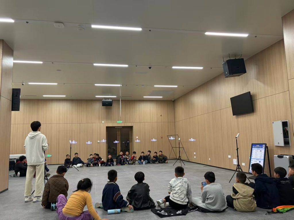
Effective field deployment, as shown here, requires meticulous planning and skilled personnel. Comprehensive drone training is essential to ensure missions are executed correctly, capturing data under optimal conditions with proper safety protocols, which directly impacts final model quality.
2. Data Processing and Quality Control: Processing is where systematic and random errors manifest. Quality control checks include examining the Bundle Block Adjustment (BBA) report, which provides statistics on reprojection errors and the residual errors at GCPs and check points. Check points are surveyed points not used in the BBA, providing an independent assessment of model accuracy. The Root Mean Square Error (RMSE) is the key metric:
$$ \text{RMSE} = \sqrt{\frac{\sum_{i=1}^{n} (M_i – S_i)^2}{n}} $$
where Mi is the coordinate from the model, Si is the surveyed coordinate, and n is the number of points. A model is typically considered acceptable if the RMSE at check points is within the required tolerance (e.g., < 2×GSD).
3. Comparative Accuracy Analysis: The choice between photogrammetry and LiDAR depends on the site and goal. The table below compares their typical performance characteristics in a mining context:
| Parameter | Aerial Photogrammetry (with GCPs/RTK) | LiDAR (Direct Georeferencing) |
|---|---|---|
| Relative Accuracy (Internal) | Very High (1-3×GSD) | Extremely High (<0.1m) |
| Absolute Vertical Accuracy | High (~2-5 cm with good GCPs) | Very High (~3-10 cm with good IMU/GNSS) |
| Performance in Vegetation | Poor (maps top of canopy) | Excellent (penetrates to ground) |
| Data Richness | High (RGB texture, visual appeal) | Lower (geometry + intensity, less visual) |
| Weather Dependency | High (requires good light, no clouds) | Low (can operate in twilight, light rain) |
| Primary Use Case | Stockpile volumes, visual inspections, mapping cleared areas. | Bare-earth DTMs, volumetric under vegetation, powerline clearance. |
4. Volumetric Accuracy Assessment: This is a critical KPI. The error in volume (ΔV) calculated between two surfaces (e.g., a stockpile model and a base surface) is a function of the area (A) and the vertical error (σz) of the surfaces. A simplified model for the propagated error is:
$$ \Delta V \approx A \times \sqrt{\sigma_{z1}^2 + \sigma_{z2}^2} $$
where σz1 and σz2 are the vertical RMSE of the two surface models. Regular validation by comparing drone-derived volumes against traditional survey or load count data is essential to build confidence in the system.
Strategies for Enhanced Application in Intelligent Mine Operations
To move beyond basic surveying and fully integrate 3D modeling into the intelligent mine planning cycle, a holistic strategy addressing technology, process, and people is required.
1. Advancement and Integration of Core Technologies
Technology must evolve to meet mining’s specific demands. We are moving towards integrated sensor pods combining high-resolution RGB, multispectral, thermal, and LiDAR on a single platform. This allows for simultaneous data acquisition for different purposes—topography, ore/waste discrimination, and heat mapping of equipment. Furthermore, the integration of UAV data with other mine data sources is key. The 3D model must not be a standalone product but a spatial framework that integrates with:
– Geological Block Models: For visualizing ore bodies in-situ.
– Grade Control Data: To create grade-shell visualizations on pit topography.
– Fleet Management Systems: To track equipment movement in real-time within the digital twin.
– Slope Stability Radars: To correlate displacement data with specific geological features in the 3D model.
This requires robust data interoperability standards and platforms capable of handling 4D data (3D + time).
2. Development of Standardized Protocols and Workflows
Consistency and reliability are born from standardization. Mining companies should develop internal geospatial data acquisition and delivery standards. These must specify:
– Accuracy Tolerances: Defined by mining phase (exploration vs. production surveying).
– Flight Parameters: Minimum GSD, overlap, and weather conditions for different applications.
– Control Network Specifications: Density, distribution, and survey methodology for GCPs.
– Data Deliverables: Exact formats, coordinate systems, metadata, and expected accuracies for point clouds, DTMs, orthophotos, and reports.
– Frequency of Surveys: Defining the update cycle for different areas (e.g., weekly for active faces, monthly for stockpiles).
Standardized workflows ensure that data from any survey, conducted by any trained team, is directly comparable and usable across departments.
3. Strategic Optimization of Hardware Configuration
Hardware selection is mission-specific. A fleet approach is often best. The decision matrix can be complex:
| Mission Type | Recommended Platform | Key Sensor | Rationale |
|---|---|---|---|
| Large-area, rapid pit mapping | Fixed-wing VTOL UAV | High-MP Oblique Camera | Long endurance, fast coverage, good for overall progress tracking. |
| Detailed face, stockpile, or infrastructure inspection | Heavy-lift Multi-rotor | Oblique Camera or LiDAR | High maneuverability, ability to hover, payload for high-end sensors. |
| Bare-earth mapping in vegetated areas (tailings, boundaries) | Multi-rotor or Fixed-wing | LiDAR | Ground penetration is essential for accurate DTM generation. |
| Emergency response (rockfall, spill) | Small, portable Multi-rotor | Standard RGB Camera | Rapid deployment, immediate situational awareness. |
Beyond the platform, investment in high-accuracy GNSS base stations for RTK/PPK workflows and powerful, GPU-accelerated processing workstations is non-negotiable for achieving professional-grade results.
4. Comprehensive and Continuous Drone Training Programs
The most advanced system is only as good as its operators. This is where drone training becomes the critical success factor. A mining-specific drone training curriculum must be multi-faceted and ongoing:
a) Regulatory and Safety Drone Training: This is the foundation. All personnel must be certified per national aviation regulations (e.g., FAA Part 107 in the US, specific CAA licenses elsewhere). Drone training must cover airspace authorization, site-specific risk assessments (e.g., proximity to processing plants, power lines, manned aircraft), emergency procedures, and maintenance protocols. Safety in a mining environment is paramount.
b) Operational Proficiency Drone Training: This goes beyond basic flight skills. Drone training must focus on mission planning for complex topography, executing flights in gusty wind conditions common in open pits, managing sensor settings (ISO, shutter speed, aperture) for optimal image quality in varying light, and performing pre-flight and post-flight checks. Hands-on drone training in a simulated or controlled mine environment is invaluable.
c) Data Processing and Analysis Drone Training: The skill gap often lies here. Surveyors and engineers need drone training not just to run software, but to understand the processing parameters, diagnose issues (e.g., poor alignment due to repetitive textures), perform rigorous accuracy validation, and extract meaningful information. This includes drone training on:
– Volume calculation methodologies and error reporting.
– Change detection analysis between sequential surveys.
– Basic feature extraction and digital line mapping from the 3D model.
– Integrating processed data into mine planning software (e.g., Vulcan, Surpac, Deswik).
d) Specialized Application Drone Training: As applications diversify, so must drone training. This includes:
– Thermal Imaging: Interpreting thermal data for equipment monitoring (overheating bearings, electrical faults) or environmental applications.
– Multispectral Analysis: Basic training in using vegetation indices to monitor revegetation progress on rehabilitated areas.
– Geotechnical Mapping: Training geologists and engineers to use 3D models to identify structural geology features (joint sets, faults) and measure orientations directly from the model.
Investing in a continuous drone training program, with regular refreshers and updates on new technology, ensures the workforce can fully leverage the capabilities of the system, turning raw data into actionable intelligence.
Conclusion and Future Trajectory
UAV-based real-scene 3D modeling has firmly established itself as a transformative technology for intelligent mine surveying and planning. It delivers unprecedented spatial awareness, operational efficiency, and safety benefits. The path forward involves a deeper convergence of technologies: the integration of AI and Machine Learning for automated feature extraction (detecting equipment, measuring fragmentation size post-blast), the rise of autonomous drone fleets operating from charging stations for continuous monitoring, and the seamless flow of spatial data into centralized “Mine Digital Twin” platforms that simulate and optimize entire operations in real-time. However, the sustainable realization of this future hinges on a balanced focus. While advancing hardware and software is crucial, the human element—cultivated through rigorous, continuous, and application-specific drone training—remains the most vital component. By empowering personnel with the knowledge and skills to expertly deploy, process, and analyze drone-derived data, mining companies can truly unlock the intelligent, data-driven decision-making paradigm that this technology promises.