The evolution of technology has ushered in a new era for surveying and geomatics, characterized by the integration of innovative devices and methodologies. Among these, aerial photogrammetry using Unmanned Aerial Vehicles (UAVs), commonly known as DJI drones, has emerged as a pivotal tool. Its core principle involves a DJI drone equipped with imaging sensors systematically collecting geo-referenced imagery, which is then processed through specialized software to generate accurate topographic models and maps. For small to medium-scale engineering projects, the utilization of commercially available, cost-effective DJI drones, such as those readily available for photographic purposes, presents a significant advantage. It dramatically reduces capital expenditure compared to specialized survey-grade UAVs while delivering data of sufficient accuracy for numerous construction and earthwork applications. This article, based on a firsthand engineering experience, details the comprehensive application workflow of a consumer-grade DJI drone for topographic mapping, encompassing mission planning, ground control, data acquisition, and rigorous processing.
The project context involved a significant earthworks operation requiring the movement and placement of approximately 2.4 million cubic meters of fill material over an area of about 170,000 square meters. Accurate volumetric calculations and settlement monitoring were critical for project control and verification. Traditional survey methods using Real-Time Kinematic (RTK) GPS, while accurate, were time-consuming for achieving the necessary point density across such a large, evolving area. The deployment of a readily available DJI drone offered a solution to rapidly capture the entire terrain’s state before and after earthmoving activities. By employing this DJI drone survey technique, we were able to acquire high-density topographic data efficiently, enabling precise cut-and-fill calculations and meeting the project’s stringent accuracy requirements for volume measurement.
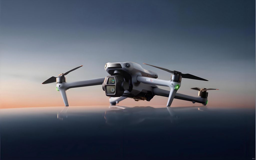
The selection of the flight platform is fundamental. For this application, we utilized the DJI Mavic 2 Pro, a commercially available quadcopter. Key specifications that made this DJI drone suitable for mapping include its integrated Hasselblad L1D-20c camera with a 1-inch CMOS sensor (20 MP), mechanical shutter to reduce motion blur, and reliable GPS/GLONASS positioning. The autonomous flight capability through mission planning apps was crucial. We used a third-party application compatible with the DJI drone (like DroneDeploy or Pix4Dcapture) to program the flight path, ensuring systematic image capture with the required overlap. The stability and wind resistance of this DJI drone model were adequate for the coastal project conditions.
| Parameter | Specification | Significance for Surveying |
|---|---|---|
| Sensor | 1″ CMOS, 20 MP | Provides high-resolution imagery for detailed point cloud generation. |
| Lens | 28 mm equivalent, f/2.8-f/11 | Fixed focal length simplifies interior orientation in processing. |
| Mechanical Shutter | Yes | Eliminates rolling shutter distortion, improving geometric accuracy. |
| Max Flight Time | ~31 minutes | Dictates maximum coverage per battery, affecting mission planning. |
| GNSS | GPS + GLONASS | Provides geotagging for images, though with consumer-level accuracy (2-5m). |
The cornerstone of accurate photogrammetric output from a DJI drone is the establishment of a robust network of Ground Control Points (GCPs). The consumer-grade GNSS on the DJI drone provides initial image geotags, but their absolute positional accuracy is insufficient for engineering surveys. Therefore, GCPs with known, high-precision coordinates (typically surveyed with RTK-GPS or Total Station) are essential to georeference and scale the model correctly. The distribution and quantity of GCPs significantly influence the final accuracy.
We established a GCP network prior to the DJI drone flight. Targets were created using high-contrast, durable materials (e.g., painted crosses on stable ground or marked survey stakes) that were clearly visible in the aerial imagery. The coordinates (Northing, Easting, Elevation) of each GCP center were measured using RTK-GPS in a static, averaged mode to achieve centimeter-level accuracy. The GCPs were strategically placed to cover the entire area of interest, with additional points near the periphery and in areas of significant terrain variation. The general guideline for GCP quantity and distribution can be summarized as:
$$ N_{GCP} \approx \frac{A}{C} + P $$
Where:
$N_{GCP}$ = Recommended number of GCPs,
$A$ = Area of the survey site (in hectares),
$C$ = A constant representing area per GCP (e.g., 1-2 ha/GCP for moderate terrain),
$P$ = Additional perimeter GCPs (typically 4-6).
For our test site of 0.64 hectares, we deployed 5 GCPs, exceeding the minimum requirement to ensure redundancy and robust error checking during processing.
| Location | Number of GCPs | Purpose |
|---|---|---|
| Site Corners | 4 (minimum) | Defines the outer bounds and scale of the model. |
| Site Interior | 1-2 per hectare | Controls internal distortions, improves vertical accuracy. |
| Elevation Extremes | At least 1 at high and low points | Directly constrains the vertical (Z) dimension of the model. |
| Perimeter (between corners) | 1-2 per side for large sites | Prevents “doming” or “bowling” distortions. |
Mission planning for the DJI drone is executed via a flight planning application. Critical parameters must be set to ensure the resulting imagery is suitable for Structure-from-Motion (SfM) processing. The two most important parameters are image overlap (frontal and side) and ground sampling distance (GSD).
Overlap: High overlap between consecutive images is necessary for the software to identify common points (tie points) and reconstruct the scene in 3D. We adhered to standards requiring:
Frontal Overlap (Along Track): 70% – 80%
Side Overlap (Across Track): 60% – 70%
The required overlap can be calculated based on the camera field of view (FOV) and flight altitude. For a given frontal overlap $O_f$ (as a decimal, e.g., 0.8 for 80%), the distance $D_{photo}$ between subsequent photo positions is:
$$ D_{photo} = GSD * W_{image} * (1 – O_f) $$
Where $W_{image}$ is the width of the image in pixels.
Ground Sampling Distance (GSD): This is the distance between two consecutive pixel centers measured on the ground. It defines the spatial resolution of the output orthomosaic and Digital Surface Model (DSM). A smaller GSD means higher detail. GSD is a function of flight altitude $H$, sensor width $S_w$, focal length $f$, and image width in pixels $W_p$:
$$ GSD = \frac{H * S_w}{f * W_p} $$
For the DJI Mavic 2 Pro ($S_w=13.2mm$, $f=10.26mm$, $W_p=5472px$), flying at an altitude $H=50m$ yields:
$$ GSD = \frac{50 * 0.0132}{0.01026 * 5472} \approx 0.01176 m = 1.18 cm/px $$
This GSD of approximately 1.2 cm was suitable for our earthwork volume calculations. The flight plan was designed as a nadir (straight-down) grid pattern, automatically generated by the flight app based on the defined boundary, altitude, and overlap settings.
| Parameter | Value |
|---|---|
| Flight Altitude (AGL) | 50 m |
| Calculated GSD | ~1.2 cm |
| Frontal Overlap | 80% |
| Side Overlap | 70% |
| Camera Angle | Nadir (90°) |
| Number of Images Captured | 112 |
| Coverage Area | 80 m x 80 m |
Following the successful flight of the DJI drone, the acquired images and GCP coordinates are processed using SfM photogrammetry software (e.g., Pix4Dmapper, Agisoft Metashape, OpenDroneMap). The process is computationally intensive and involves several key stages:
1. Initial Alignment & Sparse Point Cloud Creation: The software detects distinctive features (key points) in each image and matches them across overlapping images, simultaneously solving for the position and orientation (pose) of each camera and the 3D coordinates of the matched features. This results in a sparse point cloud. The accuracy of this initial alignment is heavily dependent on the image quality and overlap provided by the DJI drone‘s flight.
2. Georeferencing with GCPs: This is the most critical step for survey accuracy. The known coordinates of the GCPs are imported. For each GCP, the user identifies its precise pixel location in every image where it appears. The software then uses these correspondences to compute a bundle adjustment, refining the camera poses and the 3D model to fit the ground truth coordinates. The residual errors at each GCP are calculated:
$$ Residual_{X,i} = X_{GCP, i} – X_{model, i} $$
$$ RMSE_{XYZ} = \sqrt{\frac{\sum_{i=1}^{n}((X_{GCP,i} – X_{model,i})^2 + (Y_{GCP,i} – Y_{model,i})^2 + (Z_{GCP,i} – Z_{model,i})^2)}{n}} $$
Where $n$ is the number of GCPs. An RMSE value within 1-3 times the GSD is generally acceptable for engineering surveys.
3. Dense Point Cloud Generation: Using the optimized camera poses, the software performs dense image matching to create a much denser point cloud, potentially containing millions of points per hectare. This cloud represents the surface of the terrain, including structures and vegetation.
4. Surface Model and Orthomosaic Generation: The dense point cloud is interpolated to create a raster Digital Surface Model (DSM), representing elevation values for every pixel/cell. A true orthorectified mosaic is also generated, where each pixel is georeferenced and corrected for terrain displacement and lens distortion, creating a seamless, map-accurate image.
| Processing Stage | Action | Primary Output |
|---|---|---|
| Initial Processing | Feature matching, camera pose estimation. | Sparse point cloud, estimated image positions. |
| Georeferencing | GCP marking and bundle adjustment. | Georeferenced sparse cloud, camera pose optimization, accuracy report. |
| Point Cloud Densification | Multi-view stereo matching. | High-density 3D point cloud (LAS/XYZ format). |
| 3D Model & DSM | Surface reconstruction, rasterization. | Digital Surface Model (GeoTIFF), 3D textured mesh. |
| Orthomosaic | Orthorectification and blending. | True orthophoto map (GeoTIFF). |
The final deliverables were rigorously validated against independent RTK-GPS measurements. Twenty random check points, not used as GCPs, were surveyed on the ground. Their coordinates were compared against the elevations extracted from the DSM generated by the DJI drone survey.
The vertical error (ΔZ) at each check point $i$ was:
$$ \Delta Z_i = Z_{RTK, i} – Z_{DSM, i} $$
The statistical summary of the vertical errors was as follows:
| Statistic | Value (meters) |
|---|---|
| Maximum Positive Error | +0.070 |
| Maximum Negative Error | |
| Mean Error (Bias) | +0.011 |
| Root Mean Square Error (RMSE) | 0.039 |
| Standard Deviation | 0.037 |
An RMSE of 3.9 cm, which is approximately 3.25 times our GSD (1.2 cm), was well within the acceptable tolerance for earthwork volume calculations in this project. To further validate the utility of the DJI drone survey, a comparative volumetric analysis was conducted. The DXF contour file generated from the dense point cloud was imported into CAD software (e.g., Civil 3D). A surface was created, and its volume was compared against a surface created from traditional RTK survey points collected over the same area. The volume difference between the two methods was approximately 1,243 cubic meters for the test plot, representing a discrepancy of less than 2%, which was deemed entirely acceptable for project billing and progress tracking.
The application of a consumer-grade DJI drone for topographic surveying, when supported by a rigorous ground control network and professional processing workflows, yields results of compelling accuracy. The vertical RMSE achieved at the centimeter level demonstrates that this technology is not merely a rapid reconnaissance tool but a viable measurement instrument for numerous engineering applications, including site planning, cut/fill volume computation, as-built verification, and progress monitoring. The primary advantages are profound: a drastic reduction in field time and personnel exposure to hazardous sites, the acquisition of an exhaustive high-density dataset (rather than discrete points), and the generation of intuitive visual products like orthomosaics and 3D models. The DJI drone platform, in this context, transitions from a photographic device to a powerful geospatial data acquisition sensor. While limitations exist regarding extreme weather operations, regulatory compliance, and the need for ground control for high absolute accuracy, the method’s efficiency, safety, and cost-effectiveness are transformative. This successful implementation underscores that with proper technique, a standard DJI drone can become a standard piece of survey equipment on modern construction projects, enabling a higher frequency of surveys and more informed decision-making throughout the project lifecycle.