In modern aerial combat environments, the survivability of a fixed-wing UAV is critically dependent on its ability to perform rapid lateral maneuvers to evade incoming threats. Traditional single-engine fixed-wing UAVs rely solely on rudder deflection for yaw control, which often results in low turn rates and high vulnerability. To address this limitation, I designed a novel lateral high overload system for a twin-engine fixed-wing UAV that integrates differential thrust from two electric motors with a unified rudder and water rudder configuration. This system enables the fixed-wing UAV to achieve significantly higher yaw moments, thereby reducing the probability of being destroyed by weapon systems. In this article, I present the mathematical modeling, simulation analysis, and key design parameters of this system, demonstrating its effectiveness across a range of flight speeds and thrust conditions.
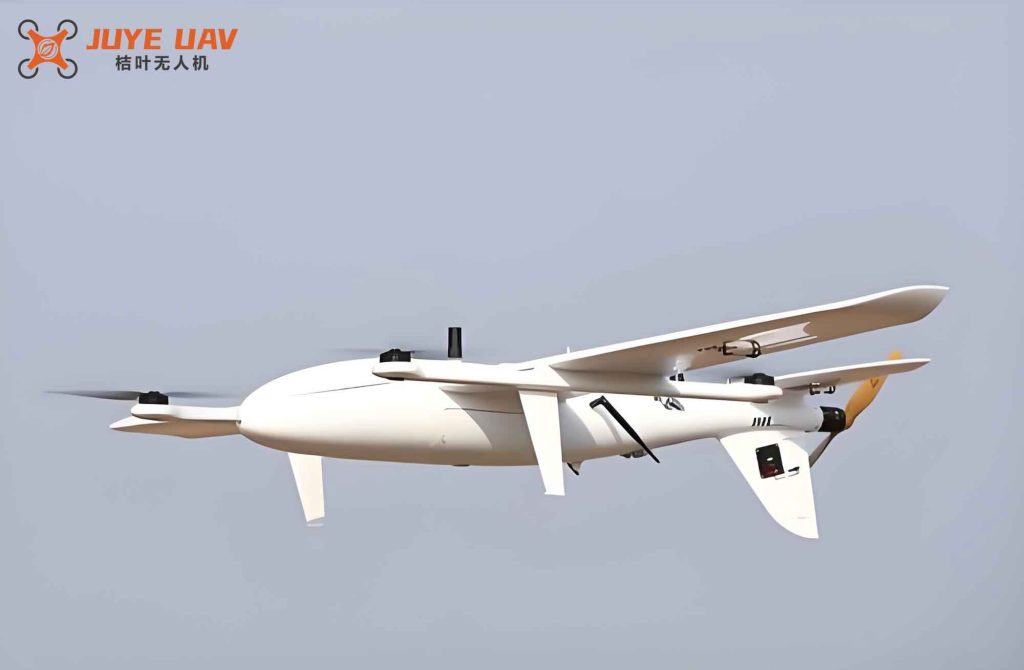
My design is based on a sea-air amphibious fixed-wing UAV with a take-off mass of 20 kg, a maximum wingspan of 1.6 m, and a speed range from 1 m/s to 38 m/s. The twin motors are mounted symmetrically on the wings, each capable of providing up to 30 N of thrust. The vertical tail incorporates a combined rudder and water rudder with a total area of 0.2 m². By controlling the differential speed of the two electric motors and the deflection angle of the unified rudder, the fixed-wing UAV can execute rapid yawing maneuvers without significant loss of forward speed.
Mathematical Model of Lateral Yaw Torque
To quantify the yaw moment generated by the differential thrust, I define the torque contributed by the twin motors as:
$$ M_1 = F_2 \cdot L_2 – F_1 \cdot L_1 $$
where \( F_1 \) and \( F_2 \) are the thrust forces of the left and right motors respectively, and \( L_1 \) and \( L_2 \) are the corresponding moment arms from the center of gravity. For symmetric installation and simplified control, I set \( L_1 = L_2 = L \), so that:
$$ M_1 = (F_2 – F_1) \cdot L $$
The total vertical tail area \( S \) consists of the fixed vertical stabilizer area \( S_1 \), the rudder area \( S_3 \), and the water rudder area \( S_4 \), such that \( S = S_1 + S_3 + S_4 \). When the unified rudder is deflected to its maximum angle, the side force generated is:
$$ F_3 = \frac{1}{2} \rho v^2 C_z S $$
where \( \rho \) is the air density, \( v \) is the flight speed, and \( C_z \) is the side force coefficient. The corresponding yaw torque from the rudder alone is:
$$ M_2 = F_3 \cdot L_3 = \frac{1}{2} \rho v^2 C_z S L_3 $$
Here, \( L_3 \) is the distance from the center of gravity to the aerodynamic center of the vertical tail. The combined torque \( M \) from both the differential thrust and the rudder deflection is:
$$ M = M_1 + M_2 = (F_2 – F_1) \cdot L + \frac{1}{2} \rho v^2 C_z S L_3 $$
This equation forms the basis for evaluating the lateral maneuverability of the fixed-wing UAV. For a left turn scenario, I set the left motor thrust to zero (\( F_1 = 0 \)) to maximize the differential effect, and the right motor provides the turning moment. The moment arm \( L \) is a key design parameter that influences both structural stability and torque output.
Analysis of Torque versus Moment Arm with Single-Motor Thrust
Table 1 shows the calculated yaw torque \( M_1 \) as a function of moment arm \( L \) for different single-motor thrust values when the other motor is inactive. These values assume the fixed-wing UAV is stationary in terms of forward speed, focusing purely on the differential thrust contribution.
| L (m) | 4 N thrust | 15 N thrust | 30 N thrust |
|---|---|---|---|
| 0.1 | 0.4 | 1.5 | 3.0 |
| 0.2 | 0.8 | 3.0 | 6.0 |
| 0.3 | 1.2 | 4.5 | 9.0 |
| 0.4 | 1.6 | 6.0 | 12.0 |
| 0.5 | 2.0 | 7.5 | 15.0 |
| 0.6 | 2.4 | 9.0 | 18.0 |
| 0.7 | 2.8 | 10.5 | 21.0 |
| 0.8 | 3.2 | 12.0 | 24.0 |
From Table 1, it is evident that increasing the moment arm \( L \) directly amplifies the available torque. However, placing the motors near the wingtips (e.g., \( L = 0.8 \) m) may compromise structural integrity and flight stability. For the present fixed-wing UAV design, I select \( L = 0.5 \) m as a compromise, which provides up to 15 Nm of torque when a single motor operates at 30 N thrust.
Torque from Unified Rudder at Various Flight Speeds
When only the unified rudder is deflected (no differential thrust), the yaw torque \( M_2 \) depends strongly on flight speed. Using the parameters \( \rho = 1.225 \) kg/m³, \( S = 0.2 \) m², \( C_z = 0.6 \) (for maximum deflection), and \( L_3 = 0.8 \) m, I computed the torque values shown in Table 2.
| v (m/s) | 1 | 5 | 10 | 15 | 20 | 25 | 30 | 35 | 38 |
|---|---|---|---|---|---|---|---|---|---|
| M₂ (Nm) | 0.019 | 0.490 | 1.960 | 4.410 | 7.840 | 12.250 | 17.640 | 23.994 | 28.268 |
Table 2 demonstrates that the rudder-induced torque increases quadratically with speed, reaching 28.27 Nm at the maximum speed of 38 m/s. However, at low speeds (e.g., 10 m/s), the torque is only about 2 Nm, which is insufficient for rapid evasion. This limitation motivates the integration of differential thrust to augment the yaw moment at all flight conditions.
Combined Torque for Various Operating Conditions
I now evaluate the combined torque \( M = M_1 + M_2 \) when both the unified rudder is deflected to its maximum angle and the left motor is set to zero thrust while the right motor provides a variable pull. The fixed-wing UAV is assumed to be flying straight before the maneuver. Tables 3–6 present the results for four representative flight speeds: 10 m/s, 20 m/s, 30 m/s, and 38 m/s. In each table, the moment arm \( L \) varies from 0.1 m to 0.8 m, and the right motor thrust is set to 4 N, 15 N, and 30 N respectively.
| L (m) | 4 N thrust | 15 N thrust | 30 N thrust |
|---|---|---|---|
| 0.1 | 2.36 | 3.46 | 4.96 |
| 0.2 | 2.76 | 4.96 | 7.96 |
| 0.3 | 3.16 | 6.46 | 10.96 |
| 0.4 | 3.56 | 7.96 | 13.96 |
| 0.5 | 3.96 | 9.46 | 16.96 |
| 0.6 | 4.36 | 10.96 | 19.96 |
| 0.7 | 4.76 | 12.46 | 22.96 |
| 0.8 | 5.16 | 13.96 | 25.96 |
| L (m) | 4 N thrust | 15 N thrust | 30 N thrust |
|---|---|---|---|
| 0.1 | 8.24 | 9.34 | 10.84 |
| 0.2 | 8.64 | 10.84 | 13.84 |
| 0.3 | 9.04 | 12.34 | 16.84 |
| 0.4 | 9.44 | 13.84 | 19.84 |
| 0.5 | 9.84 | 15.34 | 22.84 |
| 0.6 | 10.24 | 16.84 | 25.84 |
| 0.7 | 10.64 | 18.34 | 28.84 |
| 0.8 | 11.04 | 19.84 | 31.84 |
| L (m) | 4 N thrust | 15 N thrust | 30 N thrust |
|---|---|---|---|
| 0.1 | 18.04 | 19.14 | 20.64 |
| 0.2 | 18.44 | 20.64 | 23.64 |
| 0.3 | 18.84 | 22.14 | 26.64 |
| 0.4 | 19.24 | 23.64 | 29.64 |
| 0.5 | 19.64 | 25.14 | 32.64 |
| 0.6 | 20.04 | 26.64 | 35.64 |
| 0.7 | 20.44 | 28.14 | 38.64 |
| 0.8 | 20.84 | 29.64 | 41.64 |
| L (m) | 4 N thrust | 15 N thrust | 30 N thrust |
|---|---|---|---|
| 0.1 | 28.67 | 29.77 | 31.27 |
| 0.2 | 29.07 | 31.27 | 34.27 |
| 0.3 | 29.47 | 32.77 | 37.27 |
| 0.4 | 29.87 | 34.27 | 40.27 |
| 0.5 | 30.27 | 35.77 | 43.27 |
| 0.6 | 30.67 | 37.27 | 46.27 |
| 0.7 | 31.07 | 38.77 | 49.27 |
| 0.8 | 31.47 | 40.27 | 52.27 |
The data clearly show that the combined torque increases with flight speed, moment arm, and differential thrust. At the design point (L = 0.5 m, right motor thrust = 30 N), the fixed-wing UAV can achieve a total yaw torque of 16.96 Nm at 10 m/s, 22.84 Nm at 20 m/s, 32.64 Nm at 30 m/s, and 43.27 Nm at 38 m/s. These values are substantially higher than those achievable by the rudder alone, especially at low speeds, making the system highly effective for rapid evasion scenarios.
Discussion on Structural and Control Considerations
While the torque analysis indicates the potential for extreme lateral accelerations, I also consider practical constraints. The moment arm \( L \) cannot be arbitrarily large because the motor mounts would induce excessive bending moments on the wing structure. I set a maximum of \( L = 0.5 \) m for the fixed-wing UAV prototype, which balances structural safety with maneuverability. Furthermore, the unified rudder design requires careful integration of the water rudder for amphibious operations; the added area increases both aerodynamic and hydrodynamic effectiveness, but also adds drag. In normal cruising flight, only small rudder deflections are used to maintain stability, while large deflections are reserved for emergency maneuvers.
The control system of this fixed-wing UAV is designed such that moving the throttle stick diagonally (upper-left or upper-right) commands both differential motor thrust and rudder deflection simultaneously. This coordination ensures that the fixed-wing UAV turns rapidly without losing significant forward speed, which is critical for evading ground-based or airborne threats. The system is particularly valuable for unmanned combat aerial vehicles operating in contested environments where quick reactions can mean the difference between mission success and loss of the platform.
Conclusion
I have developed a comprehensive design for a lateral high overload system specifically for a twin-engine fixed-wing UAV. By combining differential motor thrust with a unified rudder and water rudder, this fixed-wing UAV can generate substantially higher yaw torques than conventional designs that rely solely on aerodynamic control surfaces. Simulation results, summarized in the tables above, demonstrate that the combined torque can exceed 40 Nm at high speeds, enabling rapid lateral acceleration and improved survivability. The selection of a 0.5 m moment arm provides a good trade-off between torque capacity and structural integrity. This work confirms that with appropriate parameter selection, a fixed-wing UAV can achieve efficient high-G lateral turns, significantly reducing its vulnerability to enemy fire. Future work will focus on flight testing of the prototype and refinement of the control algorithms to further enhance the maneuverability of the fixed-wing UAV in both air and water environments.