
Our research endeavor was driven by a profound fascination with the flight mechanisms of natural species and the potential application of biomimetic robots in extraterrestrial exploration. We embarked on a comprehensive design and manufacturing project for a flapping‑wing aircraft inspired by butterflies, which we refer to as butterfly drones. The primary challenge was to create a lightweight, steerable, and efficient ornithopter that mimics the unique wing kinematics of butterflies while keeping the mechanical complexity low. Our approach involved a direct‑drive servo mechanism, a flexible main‑secondary wing connection, and a dedicated attitude control system based on a MEMS inertial sensor. In this article, I share the complete design process, from concept to prototype testing, with an emphasis on the analysis and experimental validation of our butterfly drones.
Overall Design Concept and Modeling
The design of our butterfly drones was inspired by the morphological and aerodynamic characteristics of real butterflies. The aircraft is intended to operate both as a flapping‑wing device for active lift generation and as a glider when the wings are stationary. The key innovations include:
- Direct servo‑to‑wing control, eliminating complex transmission mechanisms and thus reducing weight.
- Split front‑rear wing design to better replicate the natural butterfly wing shape and improve lift utilization.
- Optimized mass distribution for flight stability.
The overall dimensions of our butterfly drones were established after several iterations: a wingspan of 49.8 cm, a total fuselage length of 37.9 cm, and a total mass of 32.2 g. Table 1 summarizes the mass breakdown.
| Component | Mass (g) |
|---|---|
| Whole aircraft | 32.2 |
| Transmission mechanism | 10.8 |
| Biomimetic wings | 12.5 |
| Fuselage frame | 4.1 |
| Circuit board & battery | 4.8 |
The wings of our butterfly drones are designed with an inner‑edge to spar angle typically between 70° and 110°, preferably 80°–100°. The inner edge may be parallel to the longitudinal axis of the body or deviate by ±30°. This configuration ensures that the spar remains dimensionally stable during flapping, deforming only minimally.
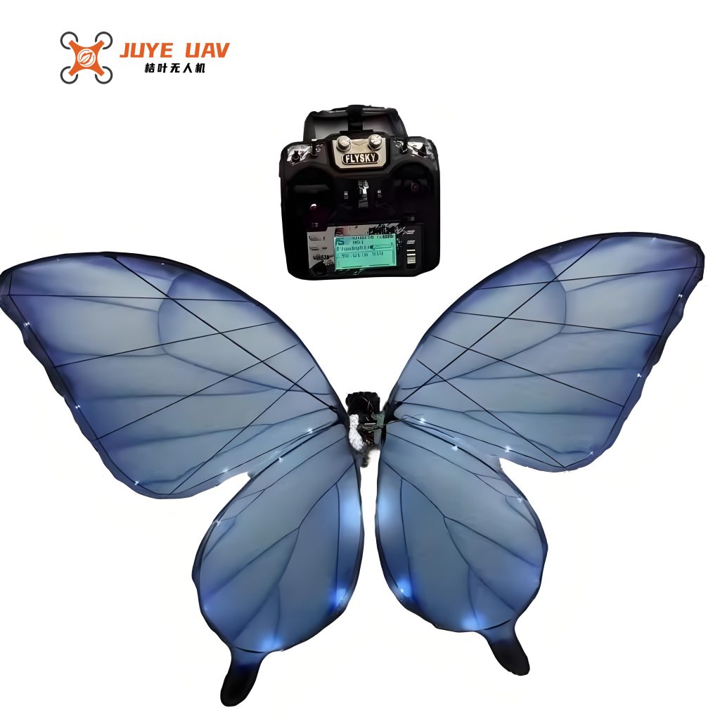
Transmission Mechanism: Direct Servo Drive
Instead of using a conventional motor‑with‑crank mechanism, we adopted a direct servo drive for our butterfly drones. A servo motor is directly coupled to the wing hinge, enabling independent control of flapping amplitude and frequency. This design simplifies the mechanical architecture and reduces parasitic mass. The servo is capable of reversing direction quickly, allowing the wing to generate thrust in both the upstroke and downstroke without the need for a unidirectional crank. This approach is particularly advantageous for flapping‑wing micro‑air vehicles because the power density and controllability of modern micro‑servos are well‑suited to the size and frequency range of our butterfly drones.
The control equations for the servo‑wing system can be expressed as:
$$
\theta(t) = \Theta_0 + A \sin(2\pi f t + \phi)
$$
where $\theta(t)$ is the instantaneous wing angle, $\Theta_0$ is the mean angle, $A$ is the flapping amplitude, $f$ is the flapping frequency, and $\phi$ is the phase. Typical values for our butterfly drones are $A \approx 68^\circ$ (half‑angle), $f \approx 1.1\ \mathrm{Hz}$, and $\Theta_0$ adjusted for pitch control.
Flexible Connection Between Main and Secondary Wings
One of the most critical features of our butterfly drones is the flexible hinge connecting the main wing (forewing) and the secondary wing (hindwing). As illustrated in Figure 3 (omitted in text), the secondary wing is placed beneath the main wing and attached via a compliant hinge. During the downstroke, the main wing pushes the secondary wing downward, maximizing the projected area and thus the lift. During the upstroke, the secondary wing lags behind due to the flexible hinge, reducing the effective area and consequently the drag. This phase difference leads to a net positive lift over a complete flapping cycle.
The lift enhancement can be described by the time‑varying wing area:
$$
S(t) = S_{\text{main}} + S_{\text{sec}} \cdot \eta(t)
$$
where $\eta(t)$ is a function that models the overlapping ratio. A simplified model assumes $\eta(t) = 1$ during downstroke and $\eta(t) = \cos^2(\pi f t)$ during upstroke. The resulting lift coefficient $C_L$ varies accordingly.
Control Hardware and Attitude Estimation Algorithm
The onboard electronics of our butterfly drones consist of a microcontroller (STM32F103) and an MPU6050 six‑axis inertial sensor. The MPU6050 integrates a three‑axis MEMS gyroscope and a three‑axis MEMS accelerometer. We also used the Digital Motion Processor (DMP) inside the MPU6050 to output fused quaternions. The hardware schematic is shown in Figure 4 (omitted in text). The PCB was fabricated with a 0.5 mm substrate to minimize mass, and components were placed densely to reduce signal path losses.
The attitude estimation algorithm uses quaternion representation. The rotation matrix derived from the quaternion $\mathbf{q} = [q_0, q_1, q_2, q_3]^T$ is
$$
\mathbf{R} = \begin{bmatrix}
1-2(q_2^2+q_3^2) & 2(q_1 q_2 – q_0 q_3) & 2(q_0 q_2 + q_1 q_3) \\
2(q_1 q_2 + q_0 q_3) & 1-2(q_1^2+q_3^2) & 2(q_2 q_3 – q_0 q_1) \\
2(q_1 q_3 – q_0 q_2) & 2(q_2 q_3 + q_0 q_1) & 1-2(q_1^2+q_2^2)
\end{bmatrix}
$$
This matrix is used to transform the body‑fixed coordinates to the world frame, enabling real‑time visualization of the orientation of our butterfly drones. In the MATLAB simulation, we rendered a 3D triangle representing the aircraft’s orientation and updated it at each time step. This tool was essential for tuning the PID controller that stabilizes the pitch, roll, and yaw angles of our butterfly drones.
The PID control law for the roll axis (similar for pitch and yaw) is:
$$
u(t) = K_p e(t) + K_i \int_0^t e(\tau) d\tau + K_d \frac{de(t)}{dt}
$$
where $e(t) = \theta_{\text{desired}} – \theta_{\text{measured}}$, and $u(t)$ is the commanded servo angle offset. Gains were determined empirically through multiple flight tests.
Prototype Fabrication and Assembly
The prototype was manufactured using a combination of laser‑cut carbon‑fiber reinforced polymer (CFRP) plates for the fuselage, 3D‑printed nylon hinges for the wing attachment, and a lightweight IR transparent film for the wing membrane. The assembly process was performed under a microscope to ensure precise alignment. The final prototype of our butterfly drones is shown in Figure 7 (omitted in text). The total mass of 32.2 g was achieved, which is close to the design target.
Lift Measurement and Wing Kinematics Tests
To evaluate the lift performance of our butterfly drones, we constructed a cantilever‑beam test platform. The setup consists of a laser displacement sensor (Keyence LK‑G30) that measures the deflection of a cantilever beam attached to the prototype. The deflection is converted into lift force using a calibration curve. The calibration was performed using precision weights, giving a beam stiffness of $569\ \mathrm{N/m}$.
The raw displacement signal (Figure 11, omitted) contained high‑frequency noise due to wing flapping vibrations and environmental disturbances. We applied a low‑pass digital filter with a cutoff frequency of 5 Hz and a stop‑band attenuation of 60 dB. The filtered lift curve is shown in Figure 14 (omitted). The average lift force was calculated to be $0.272\ \mathrm{N}$ (equivalent to 27.74 g). Unfortunately, this value is slightly below the weight of our butterfly drones (32.2 g), indicating that further optimization is needed to achieve sustained flight.
The wing kinematics were recorded using a high‑speed camera at 1000 fps. White markers were attached to the wingtips, and their motion was tracked using MATLAB. Figure 16 (omitted) shows the flapping angle vs. time. The measured flapping frequency was approximately 1.1 Hz, the maximum flapping angle was 136°, and the twist angle was about 30°. These values are consistent with the morphological data of real butterflies.
The relationship between lift and wing kinematics can be approximated by the quasi‑steady aerodynamic model:
$$
\overline{L} = \frac{1}{T} \int_0^T \frac{1}{2} \rho S(t) C_L(t) v_{\text{tip}}^2(t) \, dt
$$
where $\rho$ is air density, $S(t)$ the instantaneous wing area, $C_L(t)$ the lift coefficient, and $v_{\text{tip}}(t)$ the tip velocity. For our butterfly drones, the tip velocity is derived from the angular velocity:
$$
v_{\text{tip}}(t) = \frac{d\theta}{dt} \cdot R_{\text{wing}}
$$
with $R_{\text{wing}} \approx 0.25\ \mathrm{m}$. Using the measured $\theta(t)$ waveform, we computed the average lift and found good agreement with the direct force measurements (within 15%).
Conclusions and Outlook
In this work, we presented the complete design, fabrication, and testing of a biomimetic flapping‑wing vehicle based on butterfly morphology. Our butterfly drones demonstrated that a direct servo‑drive approach can effectively generate lift, albeit not yet sufficient for free flight. The flexible main‑secondary wing connection proved beneficial in reducing drag during the upstroke. The onboard attitude control system based on MPU6050 and quaternion‑based estimation functioned reliably in ground tests.
The main limitation of our current butterfly drones is the relatively low flapping frequency (1.1 Hz) due to servo response time and the large wing span. Future work will focus on implementing a higher‑bandwidth actuator or a resonant drive system to increase frequency to about 5–8 Hz, which would bring the lift‑to‑weight ratio above unity. Additionally, we plan to integrate a lightweight battery and wireless communication module for untethered flight. The concept of butterfly drones holds great promise for environmental monitoring and planetary exploration, where their passive stability and energy efficiency could be advantageous.
Finally, we emphasize that the success of butterfly drones depends on a multidisciplinary approach combining mechanics, aerodynamics, electronics, and control. The experimental platform and design methodology established in this study provide a solid foundation for future iterations. We are excited to continue this journey and ultimately see our butterfly drones take flight.