
In our research, we explore the realm of biomimetic micro aerial vehicles by presenting a comprehensive design and development of a butterfly-inspired flapping-wing drone. The potential applications of such vehicles in future planetary exploration, surveillance, and environmental monitoring drive our pursuit of an efficient, lightweight, and maneuverable platform. The butterfly drone we propose is directly actuated by servomotors, eliminating complex transmission mechanisms and reducing overall weight while maintaining high degrees of freedom for wing motion. This article details the conceptual design, mechanical structure, control system, fabrication process, and experimental validation of the prototype, with a strong emphasis on the underlying physics and performance metrics.
The butterfly drone is particularly attractive because of its distinctive flight characteristics: low wing loading, high lift-to-drag ratio, and agile maneuverability. In nature, butterflies achieve flight through a combination of flapping and gliding motions, with flexible wings that adapt to aerodynamic loads. Our goal is to emulate these features with a simple, robust mechanical system. The core innovation lies in using two servomotors directly driving the wings, allowing independent control of amplitude and frequency, which is crucial for attitude regulation.
Conceptual Design and Modeling
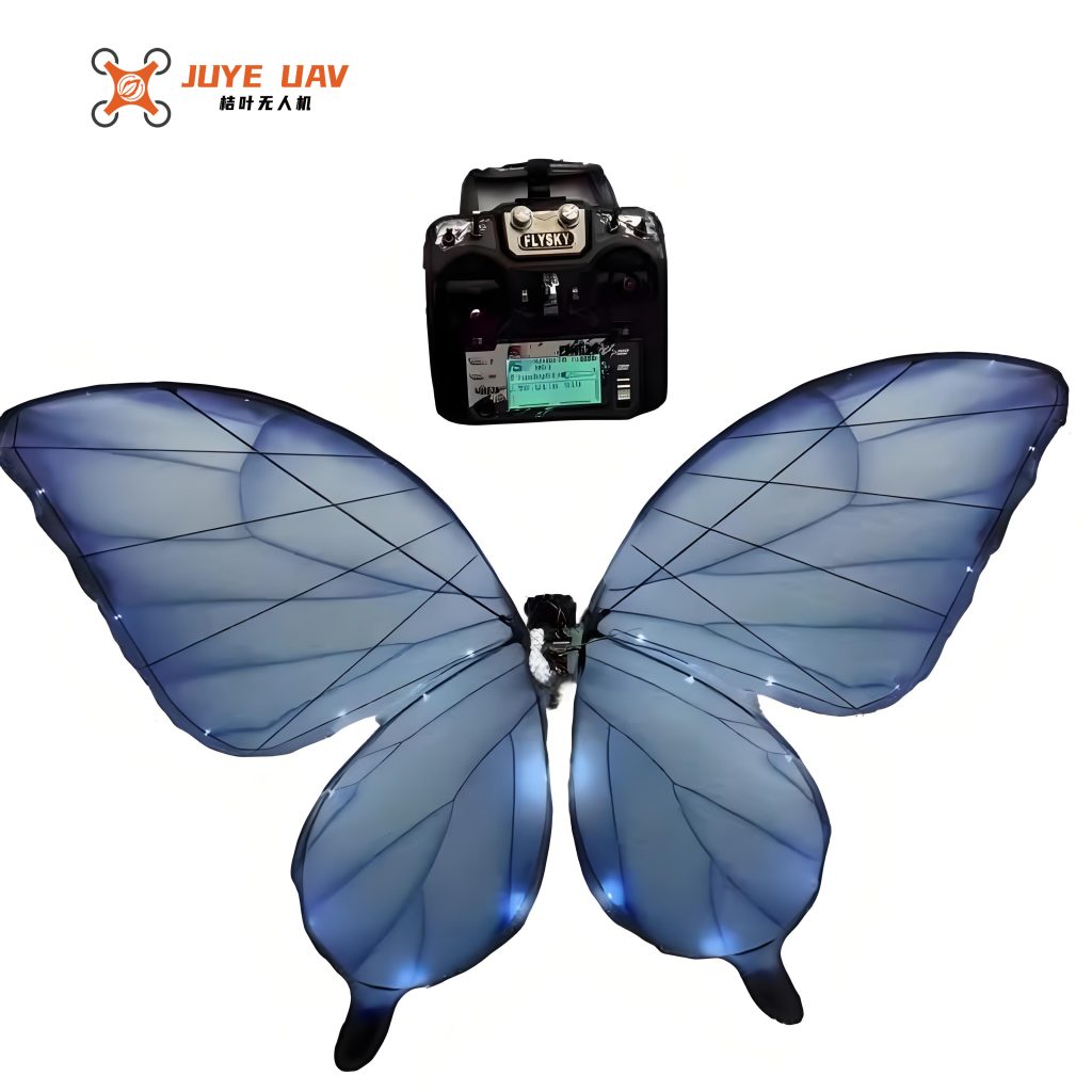
The overall architecture of the butterfly drone is inspired by the morphology of real butterflies. The fuselage is a lightweight carbon fiber frame, and the wings are constructed from thin Mylar film supported by carbon fiber spars. The wingspan measures 49.8 cm, the total body length is 37.9 cm, and the total mass is only 32.2 g. The mass distribution is critical for stable flight, and we carefully balanced the components as shown in Table 1.
| Component | Mass (g) |
|---|---|
| Complete drone | 32.2 |
| Actuation mechanism (two servos, linkages) | 10.8 |
| Wings (main and secondary) | 12.5 |
| Fuselage frame | 4.1 |
| Control board and battery | 4.8 |
The design emphasizes a high degree of freedom: each wing can be independently controlled in stroke angle and twist. The primary wing (upper) and secondary wing (lower) are connected via a flexible hinge, mimicking the natural coupling of butterfly forewings and hindwings. During the downstroke, the rigid part of the wing drives the entire surface, maximizing the projected area and generating high lift. During the upstroke, the flexible hinge allows the secondary wing to lag behind, reducing the effective area and therefore decreasing drag, a mechanism known as passive pitch variation. This behavior is captured by the kinematic model below.
The wing stroke angle $\theta(t)$ as a function of time can be approximated by a sinusoidal function:
$$ \theta(t) = \theta_0 + \frac{\Theta}{2} \sin(2\pi f t) $$
where $\theta_0$ is the mean angle, $\Theta$ is the peak-to-peak stroke amplitude (measured as 136° in our prototype), and $f$ is the flapping frequency (approximately 1.1 Hz). The twist angle $\phi(t)$ of the wing is modeled with a phase lag relative to the stroke, $\phi(t) = \phi_0 + \Phi \sin(2\pi f t + \delta)$, with $\delta$ typically around 30°.
To evaluate the aerodynamic performance, we compute the instantaneous lift $L(t)$ using a quasi-steady blade-element model:
$$ L(t) = \frac{1}{2} \rho C_L(\alpha) \int_0^{R} c(r) \, \dot{\theta}^2 r^2 \, dr $$
where $\rho$ is air density, $C_L(\alpha)$ is the lift coefficient as a function of angle of attack $\alpha$, $c(r)$ is the chord length at radial distance $r$, and $\dot{\theta}$ is the angular velocity. The average lift over one cycle is a key metric for hovering ability.
Actuation Mechanism and Control System
The butterfly drone employs two standard-sized servomotors (type MG90S) directly connected to the wing roots via short carbon fiber horns. This direct-drive approach eliminates gears, belts, or four-bar linkages, simplifying assembly and reducing weight. The servos are capable of producing a torque of about 0.2 Nm at 5 V, which is sufficient to drive the wings at 1.1 Hz. The microcontroller (STM32F103) generates PWM signals with variable pulse width and timing to control both servo positions independently.
For attitude sensing, we integrate an MPU6050 inertial measurement unit (IMU) that provides three-axis accelerometer and gyroscope data. The sensor is mounted at the center of gravity of the fuselage. A quaternion-based attitude estimation algorithm is implemented in real-time on the microcontroller. The quaternion is updated via the gyroscope integration and fused with accelerometer measurements using a complementary filter. The rotation matrix $\mathbf{R}$ derived from the quaternion $\mathbf{q} = [q_0, q_1, q_2, q_3]^T$ is given by:
$$
\mathbf{R} = \begin{bmatrix}
1 – 2(q_2^2 + q_3^2) & 2(q_1 q_2 – q_0 q_3) & 2(q_0 q_2 + q_1 q_3) \\
2(q_1 q_2 + q_0 q_3) & 1 – 2(q_1^2 + q_3^2) & 2(q_2 q_3 – q_0 q_1) \\
2(q_1 q_3 – q_0 q_2) & 2(q_2 q_3 + q_0 q_1) & 1 – 2(q_1^2 + q_2^2)
\end{bmatrix}
$$
Using this rotation matrix, we can visualize the drone’s orientation in real time on a MATLAB GUI, which assists in tuning the PID controllers for roll, pitch, and yaw. The butterfly drone’s flight control is based on differential wing amplitude and frequency. For example, to produce a roll moment, the left wing amplitude is increased while the right is decreased; yaw is controlled by shifting the mean angle of both wings in opposite directions. The control signal $u$ is computed as:
$$ U_{\text{roll}} = K_p e_{\text{roll}} + K_i \int e_{\text{roll}} dt + K_d \frac{d e_{\text{roll}}}{dt} $$
where $e_{\text{roll}}$ is the error between desired and measured roll angle. The same structure is applied to pitch and yaw loops.
Fabrication and Prototype Assembly
We developed a specialized fabrication process tailored for lightweight structures. The fuselage is cut from 1 mm carbon fiber sheet using a CNC router. The wing spars are 0.5 mm carbon rods glued into 3D-printed PLA hubs that connect to the servo horns. The wing membrane is 12 µm Mylar film, heat-sealed to the spars. The flexible hinge between forewing and hindwing is created by a thin (25 µm) polyethylene strip, allowing free rotation up to 45°.
The servos and control board are mounted on a small PCB (0.5 mm thickness) to minimize weight. The complete assembly, including a 200 mAh 1S LiPo battery (4.8 g), is shown in the figure below. The butterfly drone achieves a wingspan of 49.8 cm and a body length of 37.9 cm.
Experimental Setup and Lift Measurement
To measure the lift generated by the butterfly drone, we designed a cantilever beam test stand. The drone is mounted at the free end of an aluminum cantilever beam (1 mm thick, 20 mm wide, 300 mm long). A laser displacement sensor (Keyence LK-G30) measures the deflection of the beam tip with a resolution of 0.5 µm. The stiffness of the cantilever is calibrated using known masses, yielding a spring constant of $k = 569$ N/m. The dynamic lift force $F(t)$ is then obtained from $F(t) = k \cdot z(t)$, where $z(t)$ is the measured deflection.
The experimental platform includes a vibration isolation table to suppress external mechanical noise. The laser sensor is positioned at a reference distance of 23.5 mm from the beam. A data acquisition system (NI DAQ) samples the sensor output at 1 kHz. The drone is powered via thin wires to avoid tether effects, and its wings are set to flap at a fixed PWM signal over a period of 10 seconds. The raw displacement-time curve is recorded, as shown exemplarily in Figure (not shown), and processed with a low-pass filter (5 Hz cutoff, 60 dB stopband attenuation) to eliminate high-frequency vibrations from the flapping motion.
The instantaneous lift force after filtering is depicted in Figure (not shown). The average lift over one cycle is computed as:
$$ \bar{L} = \frac{1}{T} \int_{0}^{T} L(t) dt $$
where $T$ is the flapping period (approximately 0.91 s for 1.1 Hz). The measured average lift is 0.272 N, which corresponds to 27.74 g of mass. This is slightly less than the drone’s total weight of 32.2 g, indicating that the butterfly drone cannot achieve untethered hover without additional lift augmentation. However, with refined wing design or higher flapping frequency, we believe lift can be improved.
We also recorded the wing kinematics using a high-speed camera (1000 fps). White markers were placed on the wing tips, and custom MATLAB code tracked their positions. The wing stroke angle as a function of time was extracted, and a typical result shows a maximum stroke of 136° and a torsional angle of approximately 30°. The measured flapping frequency is accurately 1.1 Hz. The stroke-time relationship follows the sinusoidal pattern predicted by our kinematic model.
Performance Analysis and Discussion
The butterfly drone’s performance metrics are summarized in Table 2. The average lift coefficient $\bar{C}_L$ can be estimated from the measured lift using the formula:
$$ \bar{C}_L = \frac{2 \bar{L}}{\rho A \overline{v^2}} $$
where $A$ is the total wing area (approximately 0.12 m²) and $\overline{v^2}$ is the mean square wing tip velocity. For a flapping amplitude of 136° at 1.1 Hz, the mean tip speed is about 2.3 m/s, yielding $\overline{v^2} \approx 5.3$ m²/s². With $\rho = 1.225$ kg/m³, we obtain $\bar{C}_L \approx 0.72$, which is reasonable for a low-aspect-ratio flapping wing.
| Parameter | Value |
|---|---|
| Wingspan | 49.8 cm |
| Body length | 37.9 cm |
| Total mass | 32.2 g |
| Flapping frequency | 1.1 Hz |
| Maximum stroke angle | 136° |
| Torsion angle | ~30° |
| Average lift | 0.272 N |
| Equivalent lift-to-weight ratio | 0.86 |
The primary limitation of the current butterfly drone is the insufficient lift to overcome gravity. Several factors contribute: the servomotors have limited torque and speed, preventing higher flapping frequencies; the wings are relatively heavy (12.5 g) and their flexibility might cause energy losses; and the passive twist mechanism, while beneficial for drag reduction, may not generate optimal lift during the upstroke. Future improvements will focus on:
- Using lighter wing materials such as 6 µm Mylar or carbon nanotube films.
- Increasing flapping frequency to 2–3 Hz via higher-performance servos or brushless motors.
- Optimizing the wing planform and stiffness distribution using computational fluid dynamics.
- Implementing active twist control via shape-memory alloys or piezoelectric actuators.
The control system also requires refinement. The current PID gains were manually tuned; an adaptive controller or reinforcement learning approach could enable stable hovering. The IMU drift was observed over longer runs, so a magnetometer or visual odometry could be added for absolute orientation.
Despite not achieving hover, the butterfly drone demonstrated stable wing kinematics and repeatable lift generation. The direct-drive servo mechanism proved to be mechanically robust and easy to maintain. The flexible wing coupling in particular performed as expected: high-speed video confirmed that the secondary wing lags by about 20° during upstroke, reducing negative lift.
Conclusion
We have successfully designed, fabricated, and tested a bio-inspired butterfly drone that captures the essential flight mechanics of real butterflies using a simple, direct-actuation approach. The drone’s wingspan of 49.8 cm and mass of 32.2 g make it a lightweight platform suitable for future autonomous flight. The measured lift of 0.272 N at 1.1 Hz flapping frequency confirms the viability of the concept, although further optimization is needed to achieve self-powered hover. The butterfly drone’s ability to independently control wing amplitude and frequency provides a versatile testbed for flapping-wing control algorithms. Our future work will target lift enhancement and untethered flight, paving the way for practical applications such as environmental monitoring and exploration in complex terrain.