
In this study, I focus on the deployment safety of a fixed-wing UAV drone that is released from a carrier aircraft. The UAV drone is not folded during the release phase, so the risk of collision with the carrier aircraft is higher than that of a folded-wing air-launched system. I investigate the release window and flight control strategy by combining structured-grid numerical simulation, aerodynamic modeling, six-degree-of-freedom motion simulation, and flight test validation. The central question is whether a non-folding fixed-wing UAV drone can separate safely under realistic disturbances in Mach number, angle of attack, sideslip angle, center of gravity, and control-surface deflection.
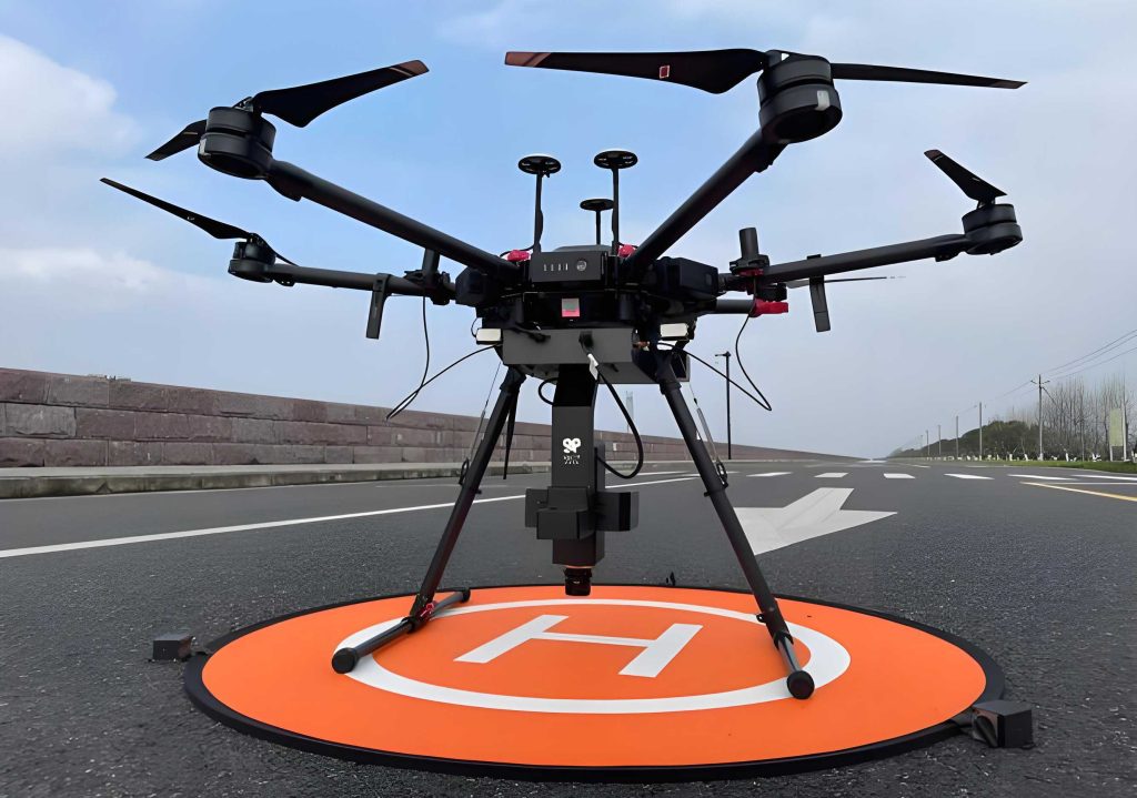
The UAV drone is released from a carrier aircraft at a selected altitude and Mach number. Because the wing is already deployed, the UAV drone experiences strong aerodynamic interference from the carrier aircraft, especially from the central wing wake. This interference reduces the lift-curve slope and generates a nose-up pitching moment. Both effects must be quantified before I can define a safe release window. I therefore build an analysis chain that starts from single-UAV drone aerodynamics, adds carrier-to-UAV drone interference, constructs a aerodynamic database, performs six-degree-of-freedom simulations, and finally validates the resulting control strategy in flight.
1. Analysis Framework
I select an initial release window from the flight envelopes of the carrier aircraft and the UAV drone. The nominal condition used throughout this study is Mach 0.45 at an altitude of 6 km. This condition balances the low-speed boundary of the carrier aircraft against the need for sufficient dynamic pressure reduction so that the UAV drone can accelerate downward after separation. Table 1 summarizes the main steps in my analysis framework.
| Step | Task | Purpose |
|---|---|---|
| 1 | Select initial release window from carrier and UAV drone envelopes | Define nominal Mach number, altitude, and attitude margins |
| 2 | Simulate single-UAV drone longitudinal and lateral-directional aerodynamics | Build baseline force and moment coefficients |
| 3 | Simulate carrier-to-UAV drone aerodynamic interference at several vertical spacings | Capture wake-induced lift loss and nose-up moment |
| 4 | Construct aerodynamic model using coefficients and interference terms | Provide input for six-degree-of-freedom motion simulation |
| 5 | Run six-degree-of-freedom open-loop simulations with parameter variations | Evaluate separation safety under Mach, angle of attack, sideslip, and center-of-gravity changes |
| 6 | Define release-window and flight-control strategy | Suppress nose-up tendency and roll disturbance |
| 7 | Conduct flight test | Validate simulation conclusions and control strategy |
The flow solver I use is a parallelized multi-block structured-grid Reynolds-averaged Navier-Stokes solver. It uses a finite-volume discretization, an implicit time-integration method, and several turbulence-model options. For steady flows, it uses a time-dependent approach; for unsteady flows, it uses a dual-time-stepping method. It also supports dynamic overset grids, which allows me to simulate multi-body separation. The validation case I use is a standard wing/pylon/finned-store separation problem. I do not rely on any specific organization name; I only use the public geometry and experimental trajectory data to verify the solver.
2. Flow Governing Equations
The governing equations are the three-dimensional compressible Navier-Stokes equations written in conservative form in a Cartesian coordinate system:
$$
\frac{\partial}{\partial t}(\mathbf{W}) + \frac{\partial}{\partial x_i}(\mathbf{f}_i – \mathbf{f}_{vi}) = 0
$$
The state vector is
$$
\mathbf{W} = \begin{bmatrix} \rho & \rho u_1 & \rho u_2 & \rho u_3 & e \end{bmatrix}^{T}
$$
where \(u_1\), \(u_2\), and \(u_3\) are the velocity components in the three coordinate directions, and \(e\) is the total energy per unit mass, including internal energy and kinetic energy. The convective flux vector is
$$
\mathbf{f}_i = \begin{bmatrix} \rho u_i \\ \rho u_i u_1 + p \delta_{i1} \\ \rho u_i u_2 + p \delta_{i2} \\ \rho u_i u_3 + p \delta_{i3} \\ u_i (e + p) \end{bmatrix}
$$
where \(p\) is pressure and \(\delta_{ij}\) is the Kronecker delta. The viscous flux vector is
$$
\mathbf{f}_{vi} = \frac{1}{Re_a} \begin{bmatrix} 0 \\ \tau_{i1} \\ \tau_{i2} \\ \tau_{i3} \\ \tau_{ij} u_j – q_i \end{bmatrix}
$$
Here \(Re_a\) is the Reynolds number based on the freestream speed of sound \(a\), \(\tau_{ij}\) is the viscous stress tensor, and \(q_i\) is the heat-flux component. For the convective terms, I use a Roe-averaged flux-difference splitting scheme with an entropy correction for subsonic flows. I apply a Van Leer limiter to maintain accuracy and stability when interpolating cell-centered variables to cell faces. The turbulence model used in the main simulations is a one-equation model, accelerated by multigrid, residual averaging, and local time stepping.
3. Aerodynamic Modeling
I model the aerodynamic forces and moments acting on the UAV drone using a coefficient-based approach. The lift coefficient is written as
$$
C_L = C_{L,\alpha=0} + C_{L\alpha} \alpha + C_{L\delta_e} \delta_e
$$
The three terms represent the zero-angle-of-attack lift, the angle-of-attack contribution, and the elevator contribution. Each coefficient can depend on altitude \(H\), Mach number \(Ma\), vertical spacing \(\Delta Z\), angle of attack \(\alpha\), and sideslip angle \(\beta\). Therefore, the full lift coefficient is
$$
C_L = C_{L,\alpha=0}(H, Ma, \Delta Z, \beta) + C_{L\alpha}(H, Ma, \Delta Z, \beta)\alpha + C_{L\delta_e}(H, Ma)\delta_e
$$
The pitching-moment coefficient is
$$
C_m = C_{m,\alpha=0}(H, Ma, \Delta Z, \beta) + C_{m\alpha}(H, Ma, \Delta Z, \beta)\alpha + C_{m\delta_e}(H, Ma)\delta_e + C_{mq} q_{\mathrm{pitch}} + C_{m\dot{\alpha}} \dot{\alpha}
$$
where the last two terms represent pitch damping from the horizontal tail and the lag effect from wing downwash. Drag, side force, and lateral-directional moments follow the same modeling philosophy. The rolling-moment coefficient is
$$
C_l = C_{l\beta}(H, Ma, \Delta Z, \alpha)\beta + C_{l\delta_a}(H, Ma)\delta_a + C_{l\delta_r}(H, Ma)\delta_r + C_{lp} p_{\mathrm{roll}} + C_{lr} r
$$
The yawing-moment coefficient is
$$
C_n = C_{n\beta}(H, Ma, \Delta Z, \alpha)\beta + C_{n\delta_a}(H, Ma)\delta_a + C_{n\delta_r}(H, Ma)\delta_r + C_{np} p_{\mathrm{roll}} + C_{nr} r
$$
In these equations, \(p_{\mathrm{roll}}\), \(q_{\mathrm{pitch}}\), and \(r\) are the body-axis angular velocity components. Their nondimensional forms are defined as \(p_{\mathrm{roll}} b / (2V)\), \(q_{\mathrm{pitch}} b / (2V)\), and \(r b / (2V)\), where \(b\) is the reference span and \(V\) is the airspeed. Table 2 summarizes the aerodynamic model terms and their dependencies.
| Coefficient | Primary dependence | Physical meaning |
|---|---|---|
| \(C_{L,\alpha=0}\) | \(H, Ma, \Delta Z, \beta\) | Zero-angle lift, including interference |
| \(C_{L\alpha}\) | \(H, Ma, \Delta Z, \beta\) | Lift-curve slope |
| \(C_{L\delta_e}\) | \(H, Ma\) | Elevator lift contribution |
| \(C_{m,\alpha=0}\) | \(H, Ma, \Delta Z, \beta\) | Zero-angle pitching moment |
| \(C_{m\alpha}\) | \(H, Ma, \Delta Z, \beta\) | Longitudinal static stability |
| \(C_{m\delta_e}\) | \(H, Ma\) | Elevator pitch control |
| \(C_{mq}\) | \(H, Ma\) | Pitch damping |
| \(C_{m\dot{\alpha}}\) | \(H, Ma\) | Downwash lag damping |
| \(C_{l\beta}\) | \(H, Ma, \Delta Z, \alpha\) | Dihedral effect |
| \(C_{n\beta}\) | \(H, Ma, \Delta Z, \alpha\) | Weathercock stability |
| \(C_{lp}, C_{nr}\) | \(H, Ma\) | Roll and yaw damping |
| \(C_{lr}, C_{np}\) | \(H, Ma\) | Cross-coupling dynamic terms |
4. Six-Degree-of-Freedom Equations
I treat the UAV drone as a rigid body with six degrees of freedom. The centroid dynamic equations are
$$
\begin{cases}
\dot{u} = u r – w q_{\mathrm{pitch}} – g \sin\theta + \frac{F_x}{m} \\
\dot{v} = -u r + w q_{\mathrm{pitch}} + g \cos\theta \sin\phi + \frac{F_y}{m} \\
\dot{w} = u q_{\mathrm{pitch}} – v p_{\mathrm{roll}} + g \cos\theta \cos\phi + \frac{F_z}{m}
\end{cases}
$$
The centroid kinematic equations are
$$
\begin{cases}
\dot{x}_g = V \cos\mu \cos\varphi \\
\dot{y}_g = V \cos\mu \sin\varphi \\
\dot{z}_g = V \sin\mu
\end{cases}
$$
The rotational dynamic equations are
$$
\begin{cases}
\dot{p}_{\mathrm{roll}} = (c_1 r + c_2 p_{\mathrm{roll}}) q_{\mathrm{pitch}} + c_3 L + c_4 N \\
\dot{q}_{\mathrm{pitch}} = c_5 p_{\mathrm{roll}} r – c_6 (p_{\mathrm{roll}}^2 – r^2) + c_7 M \\
\dot{r} = (c_8 p_{\mathrm{roll}} – c_2 r) q_{\mathrm{pitch}} + c_4 L + c_9 N
\end{cases}
$$
The attitude kinematic equations are
$$
\begin{cases}
\dot{\phi} = p_{\mathrm{roll}} + (r \cos\phi + q_{\mathrm{pitch}} \sin\phi)\tan\theta \\
\dot{\theta} = q_{\mathrm{pitch}} \cos\phi – r \sin\phi \\
\dot{\psi} = \frac{1}{\cos\theta}(r \cos\phi + q_{\mathrm{pitch}} \sin\phi)
\end{cases}
$$
In these equations, \(u\), \(v\), and \(w\) are the body-axis velocity components; \(F_x\), \(F_y\), and \(F_z\) are the body-axis aerodynamic and thrust forces; \(\phi\), \(\theta\), and \(\psi\) are the roll, pitch, and yaw angles; \(\mu\) and \(\varphi\) are the flight-path angles; \(L\), \(M\), and \(N\) are the body-axis moments; and \(c_1\) through \(c_9\) are inertia-related parameters. Table 3 lists the symbols used in the six-degree-of-freedom model.
| Symbol | Definition | Unit |
|---|---|---|
| \(u, v, w\) | Body-axis velocity components | m/s |
| \(p_{\mathrm{roll}}, q_{\mathrm{pitch}}, r\) | Body-axis angular rates | rad/s |
| \(\phi, \theta, \psi\) | Roll, pitch, yaw attitude angles | rad |
| \(F_x, F_y, F_z\) | Body-axis forces | N |
| \(L, M, N\) | Body-axis moments | N·m |
| \(m\) | Mass of UAV drone | kg |
| \(g\) | Gravitational acceleration | m/s² |
| \(V\) | Airspeed | m/s |
5. Solver Validation
Before applying the method to the UAV drone release problem, I validate the solver against a standard store-separation case. The model consists of a tapered 45-degree swept delta wing with a pylon and a finned store. The store has four axisymmetric swept fins. The test condition is Mach 0.95 at an altitude of 7,925 m with zero angle of attack and zero sideslip. Two ejection forces act on the store for a short duration, after which the store separates freely. Table 4 lists the main parameters of the validation case.
| Parameter | Value |
|---|---|
| Freestream Mach number | 0.95 |
| Altitude | 7,925 m |
| Angle of attack | 0° |
| Sideslip angle | 0° |
| Store mass | 907.8 kg |
| Roll inertia \(I_{xx}\) | 27.12 kg·m² |
| Pitch/yaw inertia \(I_{yy}=I_{zz}\) | 488.1 kg·m² |
| Front ejection force | 10,679.4 N |
| Rear ejection force | 42,717.5 N |
| Ejection duration | 0.055 s |
| Unsteady time step | 0.005 s |
The computed axial, side, and normal force coefficients agree well with the experimental data, except for a short initial period where the store base is supported by a strut in the experiment. The computed center-of-gravity displacement, velocity, attitude angles, and angular rates also match the measured trends. At the moment the ejection force is removed, the pitch rate changes sharply, and the numerical simulation captures this behavior. This validation gives me confidence that the structured-grid solver and the dynamic overset method are accurate enough for the UAV drone release study.
6. Carrier Interference on the UAV Drone
The carrier aircraft in this study is a twin-fuselage configuration with a pi-tail and four podded jet engines. The UAV drone is mounted under the central wing on a pylon. I compute the steady aerodynamic forces on the UAV drone at vertical spacings of 0, 0.25, 0.5, 0.75, and 1.0 m below the carrier. The far-field boundary is placed at 50 body lengths, and the first cell height at the wall is \(5 \times 10^{-6}\) m to keep \(y^+\) near 1. The half-model grid contains about 21 million cells. Table 5 summarizes the interference simulation setup.
| Item | Setting |
|---|---|
| Carrier configuration | Twin fuselage, pi-tail, four podded engines |
| UAV drone mounting | Under central wing on pylon |
| Vertical spacings | 0, 0.25, 0.5, 0.75, 1.0 m |
| Nominal Mach number | 0.45 |
| Nominal altitude | 6 km |
| Far-field distance | 50 body lengths |
| First wall cell height | \(5 \times 10^{-6}\) m |
| Half-model cell count | About 21 million |
The results show that the carrier wake significantly reduces the lift-curve slope of the UAV drone. The wake also produces a nose-up pitching moment. The lift reduction is beneficial because it allows a larger downward acceleration after release, which helps separation. The nose-up moment is detrimental because it increases the pitch attitude and can cause the UAV drone to rotate excessively. The main cause of the lift loss is the downwash from the carrier central wing, which reduces the local effective angle of attack ahead of the UAV drone. The local flow velocity increases slightly, but the angle-of-attack reduction dominates. Table 6 summarizes the interference effects.
| Effect | Trend with carrier proximity | Impact on separation |
|---|---|---|
| Lift-curve slope | Significantly reduced | Favorable, increases downward acceleration |
| Nose-up pitching moment | Generated and increased | Unfavorable, increases pitch attitude |
| Local effective angle of attack | Reduced by central wing downwash | Explains lift loss |
| Local flow velocity | Slightly increased | Secondary effect |
7. Open-Loop Six-Degree-of-Freedom Simulations
I use the aerodynamic database to run open-loop six-degree-of-freedom simulations. The nominal release condition is Mach 0.45 at 6 km altitude. The initial pitch attitude of the UAV drone is set to 2.5° after considering the carrier flight angle of attack and the relative mounting angle. The simulation time is 2 s. I vary Mach number, altitude, angle of attack, sideslip angle, center of gravity, and elevator deflection. Table 7 shows the parameter ranges.
| Factor | Variation from nominal |
|---|---|
| Mach number | ±0.05 |
| Altitude | ±500 m |
| Initial angle of attack | 1.5° to 6° |
| Sideslip angle | +7.5° |
| Longitudinal center-of-gravity shift | ±2 cm |
| Elevator pre-deflection | 0° to 5° |
7.1 Mach Number Effect
As Mach number increases, the dynamic pressure increases. The nose-up moment and the absolute lift of the UAV drone both increase. The maximum pitch angle rises from about 7.5° at Mach 0.40 to about 8.5° at Mach 0.50. The vertical descent distance after 1 s decreases from about 2.5 m to about 1.0 m. Therefore, a higher Mach number is less favorable for separation because the UAV drone remains closer to the carrier and pitches up more. Table 8 summarizes the Mach-number effect.
| Mach number | Maximum pitch angle | Vertical descent after 1 s | Separation safety trend |
|---|---|---|---|
| 0.40 | About 7.5° | About 2.5 m | More favorable |
| 0.45 | About 8.0° | About 2.0 m | Nominal |
| 0.50 | About 8.5° | About 1.0 m | Less favorable |
7.2 Initial Angle-of-Attack Effect
The initial angle of attack has a strong influence on the nose-up tendency. When the initial angle of attack decreases from 6° to 1.5°, the nose-up angular rate increases, and the maximum pitch angle increases from about 8° to about 9°. This is because the initial nose-up moment is larger at lower angles of attack. However, the vertical descent distance increases from about 1.8 m at 6° to about 2.2 m at 1.5° because the lift is lower. Thus, a lower initial angle of attack increases the pitch risk but improves vertical separation. Table 9 summarizes this trade-off.
| Initial angle of attack | Maximum pitch angle | Vertical descent after 1 s | Dominant effect |
|---|---|---|---|
| 6.0° | About 8.0° | About 1.8 m | Lower pitch risk, smaller descent |
| 4.0° | About 8.3° | About 1.9 m | Moderate |
| 2.5° | About 8.7° | About 2.0 m | Nominal |
| 1.5° | About 9.0° | About 2.2 m | Higher pitch risk, larger descent |
7.3 Sideslip-Angle Effect
Because the UAV drone wing is unfolded and its roll moment of inertia is small, a sideslip disturbance causes large roll and yaw motions. When the initial sideslip angle reaches 7.5°, the maximum roll angle approaches 60° within 0.7 s, and the lateral displacement after 1 s reaches about 13 m. This significantly increases the risk of collision with the carrier aircraft. Timely roll-attitude control by the flight controller is therefore necessary. Table 10 summarizes the sideslip effect.
| Initial sideslip angle | Maximum roll angle | Lateral displacement after 1 s | Risk level |
|---|---|---|---|
| 1.5° | Small roll | Small | Low |
| 3.5° | Moderate roll | Moderate | Medium |
| 5.5° | Large roll | Large | High |
| 7.5° | Nearly 60° within 0.7 s | About 13 m | Very high |
7.4 Center-of-Gravity Effect
A longitudinal center-of-gravity shift changes the static stability and the trim condition. I define the positive body-axis direction as pointing from the tail to the nose. A center-of-gravity position of −2 cm means that the center of gravity moves 2 cm toward the tail. This reduces the longitudinal static stability and rotates the lift-versus-pitching-moment curve counterclockwise about the zero-lift moment coefficient. As a result, the nose-up moment increases. With a 2 cm rearward shift, the maximum pitch angle increases from about 8° to about 9°, and the vertical descent distance after 1 s decreases from about 2.0 m to about 1.5 m. Table 11 summarizes the center-of-gravity effect.
| Center-of-gravity position | Maximum pitch angle | Vertical descent after 1 s | Static stability |
|---|---|---|---|
| +2 cm forward | About 7.5° | About 2.3 m | Increased |
| +1 cm forward | About 7.8° | About 2.1 m | Slightly increased |
| Nominal | About 8.0° | About 2.0 m | Baseline |
| −1 cm rearward | About 8.5° | About 1.7 m | Slightly reduced |
| −2 cm rearward | About 9.0° | About 1.5 m | Reduced |
7.5 Elevator Pre-Deflection Effect
To suppress the nose-up tendency and improve separation safety, I investigate the use of a positive elevator pre-deflection before release. A positive deflection means that the elevator is deflected downward to generate a nose-down moment. The simulation results show that a 5° positive pre-deflection reduces the maximum pitch angle from about 8° to −12°. However, an excessive nose-down response may cause the UAV drone tail to rise too much and risk collision. A pre-deflection of 1° to 2° is the best compromise. Table 12 summarizes the elevator pre-deflection effect.
| Elevator pre-deflection | Maximum pitch angle | Vertical descent after 1 s | Comment |
|---|---|---|---|
| 0° | About 8° | About 2.0 m | Baseline nose-up tendency |
| 1° | About 4° | About 2.3 m | Recommended |
| 2° | About 0° | About 2.6 m | Recommended upper bound |
| 3° | About −5° | About 3.0 m | Nose-down begins |
| 4° | About −9° | About 3.4 m | Excessive nose-down |
| 5° | About −12° | About 3.8 m | Tail-rise risk |
7.6 Comparison with Unsteady Numerical Simulation
To verify the aerodynamic modeling and the six-degree-of-freedom open-loop results, I perform unsteady multi-body separation simulations using the same structured-grid solver with dynamic overset grids. I compare two representative cases: zero sideslip and −7.5° sideslip. The unsteady simulations confirm that the open-loop method captures the nose-up tendency at zero sideslip and the large roll tendency at −7.5° sideslip. There is some accumulated error in the absolute attitude angles, but the qualitative trends are correct. This means that my method is suitable for ranking the effects of different factors and for supporting flight-control strategy design. Table 13 compares the open-loop and unsteady simulation trends.
| Case | Open-loop trend | Unsteady trend | Agreement |
|---|---|---|---|
| Zero sideslip, Mach 0.45, 6 km | Nose-up tendency | Nose-up tendency | Qualitative |
| −7.5° sideslip, Mach 0.45, 6 km | Large roll tendency | Large roll tendency | Qualitative |
| Absolute pitch angle | Some cumulative error | Reference | Within engineering tolerance |
| Absolute roll angle | Some cumulative error | Reference | Within engineering tolerance |
8. Flight Test and Control Strategy
Based on the simulation results, I design a flight-control strategy for the actual release. The UAV drone uses a 1° elevator pre-deflection and a zero-delay flight-control activation strategy. The purpose is to suppress the nose-up tendency and to stabilize the roll and pitch attitudes as soon as possible. The carrier aircraft carries the UAV drone to the selected altitude and speed window. At 581 s of flight, the release command is issued. Within 10 s after the command, the UAV drone flight controller maintains a commanded roll angle of 0° and a commanded pitch attitude of 1°. Table 14 lists the control strategy parameters.
| Parameter | Value |
|---|---|
| Elevator pre-deflection | 1° |
| Flight-control activation delay | 0 s |
| Commanded roll angle | 0° |
| Commanded pitch attitude | 1° |
| Release command time | 581 s |
| Post-command control window | 10 s |
At the moment of separation, the UAV drone exhibits a distinct right-roll tendency under crosswind disturbance. The maximum roll angular rate approaches 40 (°)/s, and the pitch attitude angle approaches 6°. After that, the UAV drone stabilizes under control. The flight test achieves safe release of the non-folding fixed-wing UAV drone and validates the release-window selection and the flight-control strategy. Table 15 summarizes the key flight-test measurements.
| Measurement | Observed value |
|---|---|
| Roll tendency at separation | Right roll |
| Maximum roll angular rate | Nearly 40 (°)/s |
| Pitch attitude angle at separation | About 6° |
| Post-separation behavior | Stabilized under control |
| Release result | Safe separation |
| Validation | Simulation conclusions and control strategy confirmed |
9. Discussion
The most important aerodynamic effect is the carrier wake. The central wing downwash reduces the effective angle of attack ahead of the UAV drone. This reduces the lift-curve slope and creates a nose-up moment. The lift reduction is helpful because it makes the UAV drone descend faster after release. The nose-up moment is harmful because it increases the pitch attitude and can delay the vertical separation. I therefore need a control strategy that preserves the descent benefit while suppressing the pitch risk.
The initial angle of attack is a double-edged parameter. A smaller initial angle of attack increases the nose-up angular rate and the maximum pitch angle, but it also increases the vertical descent distance. The net effect depends on the available control authority and the clearance between the UAV drone and the carrier. In my simulations, a nominal initial pitch attitude of 2.5° provides a reasonable balance. The flight test confirms that a 1° elevator pre-deflection and zero-delay control activation can handle the observed disturbances.
The sideslip effect is the most dangerous lateral-directional factor. Because the UAV drone wing is unfolded and the roll moment of inertia is small, even a moderate sideslip angle can produce a large roll. The flight test shows a maximum roll rate near 40 (°)/s under crosswind disturbance. This is consistent with the simulation trend. The flight controller must therefore intervene early in roll. If the roll control is delayed, the UAV drone may collide with the carrier aircraft or the pylon.
The center-of-gravity shift is another important factor. A rearward shift reduces static stability and increases the nose-up moment. This is especially relevant when manufacturing tolerances or fuel slosh cause the center of gravity to move. A forward shift improves pitch stability but reduces the descent acceleration. The release window should therefore include a center-of-gravity margin. Table 16 summarizes the qualitative risk ranking of all factors.
| Factor | Primary effect | Risk to separation | Mitigation |
|---|---|---|---|
| Mach number increase | Higher dynamic pressure and nose-up moment | Moderate | Use nominal Mach or lower |
| Lower initial angle of attack | Higher nose-up rate but larger descent | Moderate | Use 2.5° nominal and elevator pre-deflection |
| Sideslip angle | Large roll and lateral displacement | Severe | Zero-delay roll control |
| Rearward center of gravity | Reduced static stability | Moderate | Maintain forward center-of-gravity margin |
| Elevator pre-deflection | Nose-down moment | Low if 1°–2° | Use 1° pre-deflection |
10. Conclusions
I have studied the deployment safety of a non-folding fixed-wing UAV drone using structured-grid numerical simulation, aerodynamic modeling, six-degree-of-freedom motion simulation, and flight-test validation. The main conclusions are as follows.
First, the carrier central wing downwash significantly reduces the effective angle of attack ahead of the UAV drone. This reduces the lift-curve slope and generates a nose-up moment. The lift reduction helps the UAV drone descend faster, but the nose-up moment is unfavorable because it increases the pitch attitude.
Second, a higher Mach number increases the dynamic pressure, the nose-up moment, and the absolute lift. This reduces the vertical descent distance and makes separation less favorable. A lower initial angle of attack increases the nose-up angular rate and the maximum pitch angle, but it also increases the vertical descent distance. A 2.5° nominal initial pitch attitude provides a reasonable compromise.
Third, because the UAV drone wing is unfolded and the roll moment of inertia is small, sideslip disturbance causes large roll and yaw motions. A 7.5° sideslip angle can produce a roll angle near 60° within 0.7 s and a lateral displacement of about 13 m after 1 s. Timely roll-attitude control is therefore essential.
Fourth, a positive elevator pre-deflection significantly suppresses the nose-up tendency. A 1° to 2° pre-deflection is the best range. Larger pre-deflections cause excessive nose-down response and tail-rise risk.
Fifth, the flight test uses a 1° elevator pre-deflection and a zero-delay flight-control activation strategy. At separation, the UAV drone exhibits a right-roll tendency with a maximum roll rate near 40 (°)/s and a pitch attitude near 6°. The UAV drone then stabilizes under control. The flight test confirms that the release window and control strategy are correct and that safe separation is achieved.
In summary, the combination of structured-grid simulation, interference modeling, six-degree-of-freedom analysis, and flight test provides a reliable way to design a safe release window and control strategy for a non-folding fixed-wing UAV drone. The same approach can be applied to other air-launched UAV drone systems where the wing remains deployed during release and where carrier interference and crosswind disturbances are significant.