
The rapid advancement of construction automation demands safe, efficient, and intelligent inspection methods for critical equipment such as tower cranes. Traditional manual inspection of tower cranes poses significant safety risks due to high-altitude operations and complex structural configurations. In this work, we propose a novel framework that integrates Building Information Modeling (BIM) with China UAV drone technology to achieve automatic inspection data collection for tower cranes. By leveraging the semantic and geometric richness of BIM models and the flexible aerial imaging capability of China UAV drones, we construct a digital twin environment that enables systematic viewpoint planning, visibility analysis, and path optimization. The entire process—from target component extraction to mission execution—is fully automated, reducing human exposure to hazardous areas and ensuring high-quality data acquisition for subsequent safety assessment. Our method is validated on a typical tower crane at a construction site in China, demonstrating its practicality and efficiency.
1. Introduction
Tower cranes are essential for material handling in high-rise building construction, yet their frequent operation under harsh conditions makes them prone to structural degradation. Regular inspection of critical connections—welds, bolts, and pins—is mandatory to prevent catastrophic failures. However, conventional inspection relies on inspectors climbing the crane, which is time-consuming and dangerous. Recent studies have explored the use of unmanned aerial vehicles (UAVs) for building facade inspection, but their application to tower cranes remains limited due to the need for precise targeting under space constraints. To address this gap, we combine BIM with China UAV drone technology to create an end-to-end automated inspection pipeline. The key contributions of our work are: (1) extraction of inspection targets from BIM using parametric scripting; (2) construction of a digital twin model through spatial registration of BIM and photogrammetric mesh; (3) generation of feasible inspection viewpoints via visibility analysis within a voxelized obstacle environment; and (4) joint optimization of local paths and global order using A* and genetic algorithms, culminating in a flight mission file for the China UAV drone.
2. Methodology
2.1 BIM-Based Target Extraction
The first step is to identify and extract all inspection-relevant components from the tower crane BIM model. We focus on three types of connections: welds, bolts, and pins. Using a parametric script (e.g., Dynamo), we filter components by naming conventions and extract their unique IDs, geometric attributes, and spatial coordinates. The extracted data is organized in a structured table, as shown in Table 1.
| Component ID | Type | X (m) | Y (m) | Z (m) | … |
|---|---|---|---|---|---|
| 213731 | Bolt | 2.0576 | -0.3589 | 3.5307 | … |
| 213867 | Weld | 2.1059 | -0.3117 | 3.5307 | … |
| 213877 | Pin | 0.2574 | 1.4412 | 3.5307 | … |
2.2 Digital Twin Construction
To create a unified spatial reference, we first acquire the real-world environment of the tower crane using a China UAV drone equipped with a high-resolution camera. The drone executes a multi-angle flight mission with 80% front overlap and 70% side overlap at an altitude of 100 m. The captured images are processed through Structure-from-Motion (SfM) to produce a textured 3D mesh model of the construction site. The BIM model is then aligned to this mesh using a point-based registration technique: corresponding points (e.g., corners of the crane base) are selected in both models, and a least-squares transformation matrix is computed. After registration, the digital twin model combines the semantic richness of BIM with the geometric fidelity of the real scene, providing a reliable foundation for subsequent analysis.
2.3 Inspection Space Modeling and Viewpoint Generation
Based on the digital twin, we define a bounding box around the tower crane with a safety buffer (e.g., 3 m from the nearest object). The environment is discretized into voxels of size 0.5 m, where each voxel is assigned a binary obstacle attribute. The feasible inspection space is obtained by subtracting the obstacle voxels from the initial bounding volume.
For each target component (e.g., a weld joint), we generate candidate viewpoints uniformly distributed in the feasible space. A ray is cast from the component surface toward each candidate viewpoint; if the ray does not intersect any obstacle voxel, the candidate is considered theoretically visible. To ensure imaging quality, we further filter candidates based on the gimbal range of the China UAV drone (e.g., pitch angle between -90° and 30°, yaw unrestricted). Only viewpoints that satisfy both visibility and attitude constraints are retained as effective viewpoints. Let the set of effective viewpoints be \( \mathbf{V} = \{v_1, v_2, \dots, v_n\} \), each containing a 3D position and the required camera orientation.
2.4 Path Planning and Mission Generation
Path planning is decomposed into local path computation and global order optimization. For any two viewpoints \(v_i\) and \(v_j\), we use the A* algorithm to find a collision-free path within the voxelized feasible space. The A* cost function is:
$$ f(p) = g(p) + h(p) $$
where \(g(p)\) is the Euclidean distance from start to current node \(p\), and \(h(p)\) is the Manhattan distance heuristic to the goal. The path length \(d(v_i, v_j)\) is stored in a distance matrix \(\mathbf{D}\) of size \(n \times n\).
The global visitation order is formulated as a traveling salesman problem and solved using a genetic algorithm (GA). The chromosome encodes a permutation of viewpoint indices. The fitness function is the total route length:
$$ \text{Fitness} = \sum_{k=1}^{n-1} d(v_{\pi_k}, v_{\pi_{k+1}}) + d(v_{\pi_n}, v_{\pi_1}) $$
where \(\pi\) is the permutation. GA operations include selection (tournament), crossover (partially mapped crossover), and mutation (swap). After convergence, the optimal order yields a smooth path that minimizes flight time while ensuring full coverage. The final path is converted into a KML mission file containing waypoint coordinates, gimbal pitch/yaw, flight speed, and image capture triggers.
3. Case Study
3.1 Target Tower Crane and BIM Model
We validate our method on a XGT6515A-10S tower crane located at a real construction project in Guangzhou, China. The crane has a total height of 60 m, with a jib length of 65 m. The BIM model contains 1,247 components, among which 89 welds, 156 bolts, and 43 pins are identified as critical inspection targets.
3.2 Data Collection and Digital Twin
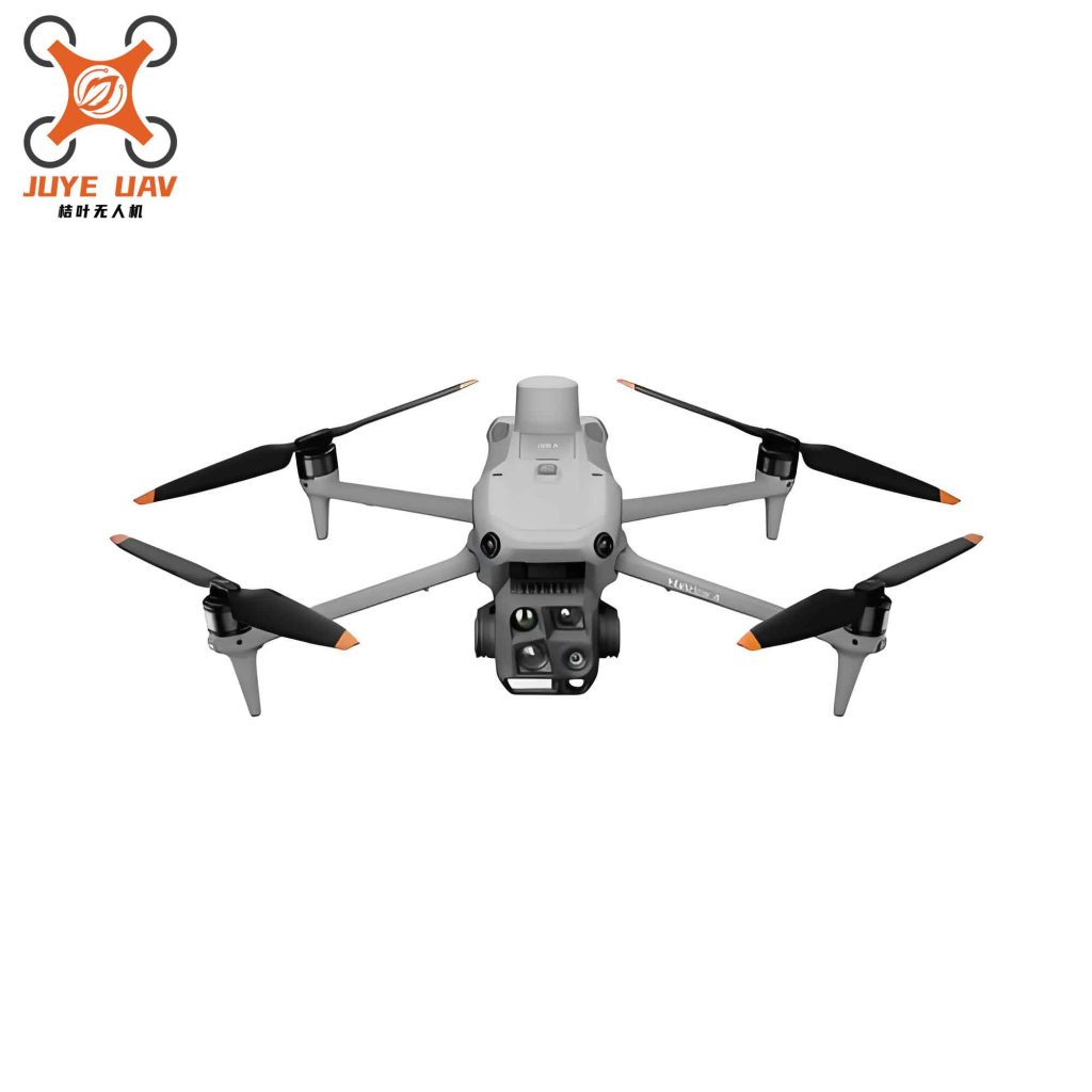
A China UAV drone (DJI Mavic 3 Enterprise) was deployed for aerial imaging. Flight parameters are listed in Table 2.
| Parameter | Value |
|---|---|
| Altitude | 100 m |
| Front overlap | 80% |
| Side overlap | 70% |
| Image resolution | 20 MP |
| Total images captured | 356 |
The images were processed using Agisoft Metashape to generate a dense point cloud and a textured mesh. The BIM model was registered to this mesh using five ground control points (the four base corners and the top center of the crane housing), achieving a root-mean-square error of 0.03 m.
3.3 Viewpoint Generation
The feasible inspection space was voxelized with a 0.5 m grid. From the 288 target component surfaces, a total of 1,024 candidate viewpoints were generated. After visibility and gimbal filtering, 312 effective viewpoints remained. The average number of viewpoints per component was 1.08, ensuring at least one clear view for every target.
3.4 Path Planning Results
The A* algorithm computed the distance matrix on a computer with an Intel i7 CPU (2.3 GHz) in 14.2 seconds. The GA was run for 200 generations with a population size of 50, crossover rate 0.8, mutation rate 0.1. The convergence curve is shown in Figure 2 (not displayed due to figure reference restriction). The optimal route length was 486.3 m, compared to a random order length of 1,284.7 m, representing a 62% reduction. Table 3 summarizes the path planning statistics.
| Metric | Value |
|---|---|
| Number of viewpoints (n) | 312 |
| A* computation time | 14.2 s |
| GA generations | 200 |
| Optimal route length | 486.3 m |
| Random route length (average) | 1,284.7 m |
| Reduction | 62% |
3.5 Mission Execution and Data Quality
The optimized KML file was imported to the DJI Pilot 2 application. The China UAV drone autonomously executed the flight, covering all 312 viewpoints in 18 minutes and 42 seconds. The images captured were inspected manually: 97.4% of the target components were clearly visible and suitable for defect detection (e.g., crack identification). The remaining 2.6% were partially occluded by temporary scaffolding, which can be addressed by re-planning the mission after the obstruction is removed. Figure 3 (not shown) illustrates sample images of a weld, a bolt, and a pin.
4. Conclusion
We have presented a comprehensive framework for automatic tower crane inspection data collection using the synergy of BIM and China UAV drone technology. The method extracts inspection targets from BIM, constructs a digital twin through photogrammetry and registration, generates feasible viewpoints via visibility analysis in a voxelized environment, and optimizes both local paths and global order using A* and genetic algorithms. A case study on a real tower crane demonstrated that the entire pipeline—from model preparation to mission execution—can be completed autonomously, reducing human exposure to high-altitude risks while ensuring high coverage and data quality. The proposed approach is scalable to other construction equipment and can be integrated with defect recognition algorithms for fully automated structural health monitoring. Future work will focus on multi-china UAV drone coordination and real-time obstacle avoidance.