The escalating verticality of urban landscapes presents a formidable challenge to conventional firefighting methodologies. The “chimney effect” inherent to high-rise structures amplifies fire intensity, complicates suppression efforts, and creates multiple pathways for rapid fire spread. Traditional apparatus, such as ladder trucks, are often hindered by physical limitations—maximum reach, obstructed access, constrained deployment environments, and protracted setup times. Consequently, the effective combat of high-rise fires remains a critical global imperative, demanding innovative solutions. In this context, the integration of Unmanned Aerial Vehicles (UAVs) into firefighting operations has emerged as a transformative paradigm. This article details a systematic approach, developed from our research and implementation work, for achieving precision fire suppression using a specialized fire drone, focusing on a ground control station (GCS)-assisted aiming methodology that enhances accuracy, reduces operator workload, and optimizes response time.
The core challenge for a fire drone tasked with external suppression of compartmental fires (e.g., through windows) is precise positioning. The drone must be maneuvered to a specific point in space where its fixed-orientation suppression nozzle (carrying water, foam, or dry chemical agent) can effectively deliver the extinguishing medium through the target aperture. Relying solely on manual remote control based on video feed and operator judgment is prone to error, especially at range and altitude, and places significant cognitive load on the operator. Our proposed system mitigates this by leveraging the drone’s onboard sensors and computational capabilities of the GCS to transform a simple operator click on the video feed into precise navigational commands.
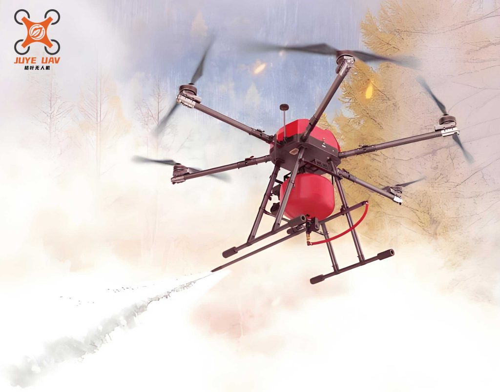
The operational concept for our large-payload fire drone involves pre-positioning at strategic fire stations within an urban network. Upon alarm, the fire drone can be launched rapidly, often arriving at the scene ahead of ground crews. It performs initial reconnaissance using its onboard camera, providing real-time situational awareness. For suppression, it carries a significant payload (e.g., 100 kg of extinguishing agent) and is equipped with a horizontal projection system. The efficacy of this system is entirely dependent on the drone’s ability to position itself accurately at the correct stand-off distance and alignment relative to the target window or opening.
System Architecture of the Precision Fire Drone
The effectiveness of the assisted aiming method is predicated on a robust and integrated system architecture. The fire drone platform is not merely a flying vehicle but a synergistic ensemble of aerial and ground-based subsystems designed for a specific mission profile. The table below summarizes the key components and their functions within our implemented system.
| System Segment | Key Components | Primary Function |
|---|---|---|
| Aerial Platform (Drone) | Airframe, Propulsion Systems, Power Supply (Batteries) | Provides stable flight, carries payload, and supplies energy to all onboard systems. |
| Avionics & Flight Control | Flight Controller, IMU, GPS, Barometer | Stabilizes the aircraft, executes flight commands, and maintains position/attitude. |
| Mission Payload | Fixed-Fire Suppression Nozzle, Payload Release Mechanism | Executes the core firefighting task by projecting extinguishing agent. |
| Sensing & Perception | Visible-Light Camera, LiDAR/ToF Sensors | Provides visual feed for operator and GCS; measures distance to obstacles (building facades). |
| Communication | 4G/5G LTE or dedicated RF Link | Establishes a robust data link between the fire drone and the GCS for command and telemetry. |
| Ground Control Station (GCS) | Software Interface, Data Processing Unit, Display | The operator’s hub for monitoring, planning, and initiating the assisted aiming procedure. |
This architecture enables a closed-loop workflow: the GCS receives telemetry (position, attitude, sensor data) and video from the fire drone. The operator interacts with the GCS interface, and the resulting commands are transmitted back to the drone’s flight controller. The assisted aiming algorithm is a key software module within the GCS that interprets operator intent and generates precise movement commands.
Mathematical Foundation of the Assisted Aiming Method
The cornerstone of our method is translating a 2D pixel coordinate on the GCS screen into a 3D displacement vector for the fire drone. This process relies on principles of projective geometry and sensor fusion.
Step 1: Determining Bearing Angles from Screen Click
When the operator clicks on a point \(M\) in the live video feed, the GCS knows the pixel coordinates \((X’, Y’)\) of this point relative to the image center \(O\). Given the camera’s intrinsic parameters—specifically its horizontal and vertical fields of view \((\alpha_{FOV_x}, \alpha_{FOV_y})\) and the image resolution in pixels \((P_x, P_y)\)—we can calculate the angular offsets.
The angular deviation of point \(M\) from the camera’s central optical axis is calculated per dimension. For the horizontal angle \(\theta_{M_x}\):
$$
\theta_{M_x} = \left( \frac{X’}{P_x / 2} \right) \cdot \left( \frac{\alpha_{FOV_x}}{2} \right)
$$
Similarly, for the vertical angle \(\theta_{M_y}\):
$$
\theta_{M_y} = \left( \frac{Y’}{P_y / 2} \right) \cdot \left( \frac{\alpha_{FOV_y}}{2} \right)
$$
The camera is fixed relative to the drone’s heading. Therefore, these angles \(\theta_{M_x}\) and \(\theta_{M_y}\) represent the horizontal and vertical bearing from the drone’s current orientation to the target point in the real world, as seen through the camera. This is the first critical output: \(\vec{\theta}_{target} = (\theta_{M_x}, \theta_{M_y})\).
Step 2: Fusing Bearing with Distance-to-Target
Knowing the direction is insufficient; we also need the distance. This is where the fire drone‘s environmental perception system, primarily forward-facing LiDAR, is crucial. The LiDAR provides a cloud of distance points. The operator, via the GCS interface, fits a virtual reference line \(L_1\) to the building facade using these LiDAR returns. This line is defined in the drone’s local coordinate system.
The line from the drone to the target, defined by the bearing \(\theta_{M_x}\), can also be expressed as a ray \(L_2\) from the origin. The intersection point \(T(x_T, y_T)\) of line \(L_1\) (facade) and ray \(L_2\) (aiming direction) gives the coordinates of the target on the facade plane relative to the drone. The horizontal distance \(S\) from the drone to the target is then:
$$
S = \sqrt{x_T^2 + y_T^2}
$$
This calculation effectively fuses the visual bearing from the camera with the spatial mapping from LiDAR to pinpoint the target’s location. The following table summarizes the parameters and their sources in this calculation phase.
| Parameter | Symbol | Source / Derivation |
|---|---|---|
| Pixel Offsets | \(X’, Y’\) | Operator click on GCS video display. |
| Camera Field of View | \(\alpha_{FOV_x}, \alpha_{FOV_y}\) | Known intrinsic parameter of the fire drone‘s camera. |
| Image Resolution | \(P_x, P_y\) | Known parameter of the video feed. |
| Bearing Angles to Target | \(\theta_{M_x}, \theta_{M_y}\) | Calculated: \(\theta_{M} = \left( \frac{X’}{P_x / 2} \right) \cdot \left( \frac{\alpha_{FOV_x}}{2} \right)\) |
| Facade Reference Line | \(L_1: A_1x + B_1y + C_1 = 0\) | Operator-defined in GCS based on LiDAR point cloud. |
| Aiming Direction Ray | \(L_2: A_2x + B_2y = 0\) | Derived from \(\theta_{M_x}\) and drone’s coordinate system. |
| Horizontal Target Distance | \(S\) | Calculated from intersection \(T\) of \(L_1\) and \(L_2\). |
Step 3: Calculating the Optimal Suppression Point
The drone should not position itself at point \(T\) (the window), but at an optimal stand-off distance \(D\) for effective agent projection. This stand-off distance \(D\) is a predetermined value based on the nozzle’s performance characteristics. The drone’s desired position, the suppression point \(P\), lies along the normal vector to the facade that passes through \(T\), at a distance \(D\) from the facade.
Geometrically, given the target point \(T\), the facade line \(L_1\), and the desired stand-off \(D\), we can calculate the vector \(\vec{V}\) from the drone’s current location \(U\) to the desired suppression point \(P\). This vector has horizontal and vertical components. The horizontal movement is derived from the triangle formed by points \(U\), \(T\), and the projection of \(P\) onto the line \(UT\). The vertical movement is directly dictated by the vertical bearing angle \(\theta_{M_y}\) and the slant distance.
The final displacement command \(\vec{\Delta}_{cmd} = (\Delta x, \Delta y, \Delta z)\) sent to the fire drone‘s flight controller is computed as follows, where \(S\) is the horizontal distance to target, \(D\) is the stand-off, and \(\theta_{M_x}, \theta_{M_y}\) are the bearing angles:
$$
\Delta x = (S – D \cdot \cos(\phi)) \cdot \sin(\theta_{M_x})
$$
$$
\Delta y = (S – D \cdot \cos(\phi)) \cdot \cos(\theta_{M_x})
$$
$$
\Delta z = S \cdot \tan(\theta_{M_y})
$$
In these equations, \(\phi\) is the angle between the drone-to-target vector and the facade normal, which is known from the geometry of line \(L_1\). Upon receiving this command, the fire drone autonomously executes the move, adjusting its yaw to face perpendicular to the facade, and arrives at the precise suppression point \(P\).
Operational Workflow and Validation
The practical application of this method follows a structured workflow that integrates the operator, the GCS, and the fire drone into a cohesive operational loop.
| Step | Action | System Role |
|---|---|---|
| 1. Deployment & Reconnaissance | Drone launches and approaches scene. Operator ascends/descends to fire floor level using video feed. | Fire drone provides mobility and live video. GCS displays data. |
| 2. Scene Mapping | Drone hovers ~20-30m from facade. Operator uses LiDAR point cloud on GCS to define building facade reference line \(L_1\). | LiDAR provides spatial data. GCS software allows line fitting. |
| 3. Target Designation | Operator enables “Assisted Aiming” mode and clicks on the specific window/fire location in the live video feed. | GCS captures pixel coordinates \((X’, Y’)\). |
| 4. Automated Calculation & Movement | GCS performs calculations as described, deriving \(\vec{\Delta}_{cmd}\). This command is sent to the drone. | GCS is the computational brain. Fire drone FC executes the precise move. |
| 5. Suppression | Drone automatically adjusts yaw to face facade. Operator confirms position via video and triggers the suppression system. | Fire drone stabilizes at point \(P\) and deploys payload. |
We have validated this system in field trials using a large-payload fire drone platform. The key performance metric was the time and accuracy of adjustment from initial hover to final suppression positioning. Prior to implementing this assisted aiming method, manual positioning relied on iterative, joystick-based adjustments guided by the video feed, a process that was time-consuming and variable. With the GCS-assisted method, the average adjustment time was reduced to approximately 15 seconds. This represents a significant increase in operational tempo and a drastic reduction in operator cognitive load during the critical targeting phase. The fire drone consistently positioned itself such that the suppression stream accurately covered the target apertures during tests.
Advantages, Considerations, and Future Outlook
The GCS-assisted aiming method fundamentally enhances the capability of a fire drone for high-rise firefighting. The primary advantages are:
- Precision: Converts qualitative visual estimation into quantitative, sensor-based positioning.
- Speed: Dramatically reduces the time-to-acquire-target compared to manual flying.
- Reduced Workload: Lowers the skill threshold and stress for the operator, who acts as a supervisor and designator rather than a precision pilot.
- Safety: Enables accurate operations from a remote location, keeping personnel out of immediate danger.
The implementation of such a system for a fire drone does present considerations. It requires calibrated and reliable sensors (camera, LiDAR). The communication link must be robust to prevent latency or dropout during the critical command phase. Furthermore, the algorithm assumes a relatively planar facade; highly irregular building surfaces may require more advanced mapping. The effectiveness of the stand-off distance \(D\) must be empirically validated for different suppression agents and nozzle types.
Future developments will likely integrate more autonomy. Machine learning could be used for automatic fire and window detection, automating the target designation step. Enhanced sensor suites, including thermal cameras for seeing through smoke, could be integrated into the aiming calculus. Furthermore, swarm coordination protocols could be developed where one fire drone performs reconnaissance and targeting for multiple suppression drones, creating a networked firefighting system.
In conclusion, the challenge of high-rise firefighting demands a leap beyond traditional tools. The intelligent fire drone, empowered by a sophisticated GCS with assisted aiming capabilities, represents a viable and powerful solution. By fusing real-time sensor data, geometric reasoning, and intuitive human oversight, this method transforms the fire drone from a remotely piloted vehicle into a precise, responsive, and force-multiplying fire suppression asset. The demonstrated reduction in positioning time and increase in operational reliability underscore its potential to revolutionize initial attack strategies for high-rise fires, ultimately contributing to saved lives and reduced property loss.