
In the evolving field of surveying and mapping, traditional methods such as total stations and RTK have increasingly shown limitations, particularly in meeting the demands for efficient, large-scale topographic mapping. As a practitioner in geomatics, I have observed that UAV drones equipped with aerial photogrammetry technology offer a transformative solution. These UAV drones enable rapid data acquisition over extensive areas, generate detailed 3D models, and enhance overall project efficiency while reducing costs. This article delves into the application of UAV drone aerial photogrammetry in topographic mapping, drawing from my experiences and technical insights to outline its processes, advantages, and practical implementation. I will emphasize key aspects like control point layout, flight planning, and data processing, incorporating tables and formulas to summarize critical concepts. Throughout, the term “UAV drones” will be frequently highlighted to underscore their centrality in modern surveying.
The core of UAV drone aerial photogrammetry lies in several advanced techniques that collectively ensure high-quality topographic outputs. Firstly, the Digital Orthophoto Map (DOM) process involves refining aerial imagery post-capture to enhance visual clarity and integrate image data with geographic information. By leveraging aerial triangulation, DOM facilitates accurate terrain representation, minimizing errors inherent in UAV drone operations. Secondly, aerial triangulation technology is pivotal; it uses sparse ground control points to encrypt and compute spatial coordinates of measurement points, enabling precise mapping with fewer field references. The mathematical basis for aerial triangulation can be expressed as solving collinearity equations, where the relationship between image coordinates and ground coordinates is defined. For a point P with ground coordinates (X, Y, Z) and image coordinates (x, y), the collinearity equations are:
$$ x – x_0 = -f \frac{a_{11}(X – X_0) + a_{12}(Y – Y_0) + a_{13}(Z – Z_0)}{a_{31}(X – X_0) + a_{32}(Y – Y_0) + a_{33}(Z – Z_0)} $$
$$ y – y_0 = -f \frac{a_{21}(X – X_0) + a_{22}(Y – Y_0) + a_{23}(Z – Z_0)}{a_{31}(X – X_0) + a_{32}(Y – Y_0) + a_{33}(Z – Z_0)} $$
Here, (x₀, y₀) is the principal point offset, f is the focal length, (X₀, Y₀, Z₀) are the camera position coordinates, and a₁₁ to a₃₃ are rotation matrix elements from orientation angles. This formulation underpins the accuracy of UAV drone photogrammetry. Thirdly, digital mapping technology automates the collection and encoding of topographic features from images, supporting the creation of 3D models that maintain data integrity. Lastly, UAV drone supplementary surveying allows for efficient re-measurement of areas with data anomalies, reducing the difficulty of field corrections. These components collectively define the technological framework of UAV drone systems, as summarized in Table 1.
| Technique | Description | Role in Topographic Mapping |
|---|---|---|
| DOM Process | Enhances aerial imagery by integrating data and reducing distortions. | Improves image quality for accurate terrain representation. |
| Aerial Triangulation | Uses control points to compute spatial coordinates via collinearity equations. | Enables precise positioning with minimal ground control. |
| Digital Mapping | Automates feature extraction and coding from images. | Facilitates efficient 3D model generation and map production. |
| Supplementary Surveying | Employs UAV drones for targeted re-measurement of missed areas. | Reduces time and cost for data correction and completion. |
UAV drones exhibit distinct characteristics that make them superior to traditional methods in topographic mapping. Primarily, they deliver high-quality data due to low-altitude operations, which capture finer details compared to satellites or manned aircraft. When integrated with GNSS and total station technologies, UAV drones achieve enhanced positional accuracy, often with errors below centimeter-level. This is quantified by error propagation models; for instance, the overall error σ in UAV drone-derived coordinates can be estimated as:
$$ \sigma = \sqrt{\sigma_{\text{GNSS}}^2 + \sigma_{\text{image}}^2 + \sigma_{\text{control}}^2} $$
where σGNSS is the GNSS positioning error, σimage is the image resolution error, and σcontrol is the control point error. Typically, UAV drones reduce σimage through high-resolution cameras, as shown in Table 2. Secondly, UAV drones offer rapid surveying efficiency; their operational simplicity allows for quick deployment and flexibility in covering hard-to-reach areas, thereby accelerating data collection. Thirdly, they provide high comprehensive benefits—modern UAV drones are cost-effective, require minimal personnel, and operate safely in diverse environments, lowering overall project expenses. These advantages have driven widespread adoption, especially in urban planning and infrastructure projects where precise, scalable mapping is crucial. The current application landscape for UAV drones is robust, with increasing use in scenarios ranging from rural surveys to dense urban areas, as illustrated by numerous successful projects.
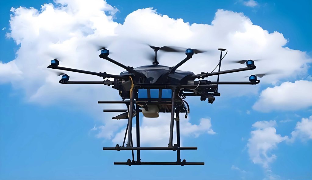
To elucidate the practical workflow, I will describe a representative topographic mapping project involving a city and its surroundings, covering approximately 125 km². This region featured complex topography, including hills, plains, and water bodies, making UAV drones an ideal choice for producing 1:500 digital topographic maps. The application process followed a structured sequence: preparatory work, control point layout, flight route design, equipment selection, aerial photography, data processing, and quality assurance. Each step is critical to leveraging UAV drones effectively, and I will detail them with technical specifics.
Initial preparatory work involves gathering project requirements and background data. I typically consult with stakeholders to define scope, technical standards, and deliverables, such as coordinate systems and accuracy thresholds. For this project, I collected geographic information from online platforms and government sources to understand terrain and land use. Based on this, I drafted a UAV drone photogrammetry plan, outlining key parameters like precision indicators and output formats. This foundation ensures that subsequent steps align with project goals, minimizing revisions.
Control point layout is a fundamental step for ensuring aerial triangulation accuracy. In my experience, UAV drones require well-distributed ground control points (GCPs) that are visible in aerial imagery. For this project, I designed 358 GCPs using painted markers—each rectangular, 0.3 m by 0.6 m—placed in overlapping areas of adjacent images. The distribution follows a grid pattern to cover the survey area uniformly, with density dependent on terrain complexity. The coordinates of these GCPs were measured using a satellite positioning system, achieving millimeter-level accuracy. The principles for GCP spacing can be expressed by the formula:
$$ D = k \cdot H \cdot \tan(\theta) $$
where D is the distance between GCPs, H is the flying height, θ is the camera field of view, and k is a constant (typically 0.1 to 0.2) based on required precision. For UAV drones, I often set D to 200–300 meters in flat areas, increasing it in rugged zones. Table 2 summarizes key parameters for GCP layout and equipment used in this project.
| Parameter | Value or Specification | Remarks |
|---|---|---|
| UAV Drone Model | Huace P330 (equipped with tilt five-lens camera) | Effective pixel: 42.4 MP; image resolution: 7952 × 5304 px |
| Flying Height | 150 m above ground level | Adjusted for terrain relief to maintain consistent GSD |
| Ground Sample Distance (GSD) | 2.5 cm/pixel | Calculated as GSD = (H × pixel size) / focal length |
| Number of GCPs | 358 | Uniformly distributed; measured via GNSS |
| Forward Overlap | 75% | Ensures continuous coverage along flight path |
| Side Overlap | 60% | Provides redundancy for 3D reconstruction |
Flight route design is another critical aspect for UAV drones. I plan routes based on flying height and overlap requirements to ensure complete coverage. For this project, I set the forward overlap at 75% and side overlap at 60%, adhering to technical guidelines like the “Oblique Digital Aerial Photography Technical Specifications.” The flying height was determined by the UAV drone’s camera parameters and desired GSD, calculated as:
$$ \text{GSD} = \frac{H \cdot s}{f} $$
where H is flying height, s is pixel size (4.5 μm for this camera), and f is focal length (e.g., 35 mm). To achieve a GSD of 2.5 cm, I computed H ≈ 150 m. The flight paths were extended beyond the survey boundaries by a buffer width B, given by:
$$ B = H \cdot \tan(\alpha) + \Delta h $$
where α is the camera tilt angle and Δh is the lowest elevation at the edge. This ensured that all peripheral features were captured. The UAV drones performed 25 flights, covering an effective area of 142 km² under clear weather conditions, yielding imagery without gaps or distortions.
Equipment selection for UAV drone surveys involves choosing appropriate hardware and software. I opted for the Huace P330 UAV drone due to its high-resolution camera and stability. For data processing, I used Smart3D for 3D modeling and EPS software for topographic mapping. These tools integrate seamlessly with UAV drone outputs, enabling efficient workflow from raw images to final maps. The synergy between UAV drones and specialized software is vital for handling large datasets, as seen in this project where thousands of images were processed.
Aerial photography with UAV drones requires meticulous execution. In this project, I conducted flights during optimal daylight hours to avoid shadows and ensure uniform illumination. The UAV drones followed pre-programmed routes, capturing images with embedded POS data. Post-flight, I verified that all areas were covered and that image quality met standards—no blurring or excessive noise was present. The success of UAV drone photography hinges on weather adherence and equipment calibration, which I prioritize to prevent re-flights.
Data processing transforms raw UAV drone imagery into usable topographic products. Using Smart3D, I performed aerial triangulation twice: first with initial POS data, then after importing GCP coordinates. This iterative process refined the bundle adjustment, reducing errors. The resulting point cloud was meshed into a 3D model, which I validated with total station measurements of key features. Discrepancies were corrected to align with accuracy standards. For error analysis, I computed root mean square error (RMSE) for plane and elevation coordinates:
$$ \text{RMSE}_{\text{plane}} = \sqrt{\frac{\sum_{i=1}^{n} (x_i – X_i)^2 + (y_i – Y_i)^2}{n}} $$
$$ \text{RMSE}_{\text{elevation}} = \sqrt{\frac{\sum_{i=1}^{n} (z_i – Z_i)^2}{n}} $$
where (xᵢ, yᵢ, zᵢ) are UAV drone-derived coordinates and (Xᵢ, Yᵢ, Zᵢ) are ground truth values. In this project, RMSE values were within 0.05 m, meeting 1:500 map specifications. The processed model was then imported into EPS software, where I digitized features like buildings, roads, and vegetation, assigning codes for map symbology. Areas obscured by trees required supplemental field surveys, but UAV drones minimized such gaps by capturing multiple angles.
Final成果整理与质量检查 involve compiling deliverables and rigorous validation. I generated digital topographic maps from the UAV drone data, then randomly selected 30% of map sheets for accuracy checks. Using a total station, I measured over 20 points per sheet, comparing them to map coordinates. The results showed mean plane errors of 0.02 m, elevation errors of 0.03 m, and spacing errors of 0.018 m, all within tolerance. This demonstrates that UAV drones can achieve high precision when processes are meticulously followed. Table 3 summarizes the error statistics and quality metrics for this project.
| Error Type | Mean Error (meters) | Maximum Error (meters) | Tolerance Limit (meters) |
|---|---|---|---|
| Plane Coordinate Error | 0.02 | 0.05 | 0.10 (for 1:500 scale) |
| Elevation Error | 0.03 | 0.08 | 0.15 (for 1:500 scale) |
| Feature Spacing Error | 0.018 | 0.04 | 0.08 (for 1:500 scale) |
| Overall RMSE | 0.025 | N/A | 0.05 (project standard) |
In conclusion, UAV drone aerial photogrammetry represents a significant advancement in topographic mapping, offering superior accuracy, efficiency, and cost-effectiveness. Based on my application in diverse projects, I find that UAV drones excel in capturing detailed terrain data, especially in complex environments. However, maximizing their potential demands skilled personnel who understand photogrammetric principles and can implement robust workflows—from control point design to data validation. As UAV drone technology continues to evolve, I anticipate further innovations in automation and integration, such as AI-based feature extraction and real-time processing. For practitioners, I recommend continuous learning and adaptation to harness UAV drones fully, ensuring that topographic mapping keeps pace with growing demands for precision and scalability. The future of surveying undoubtedly lies in the intelligent use of UAV drones, and I am committed to exploring their capabilities in my ongoing work.