In recent years, the frequency and intensity of geological hazards have increased due to various environmental and anthropogenic factors. These events, such as landslides and rockfalls, often occur in remote, rugged terrains where traditional surveying methods are challenging, time-consuming, and hazardous. As a professional involved in geohazard mitigation, I have explored advanced technologies to address these challenges. Among them, multirotor drone-based terrain-following oblique photogrammetry has emerged as a transformative tool. This technique combines the agility of multirotor drones with high-precision imaging to capture detailed three-dimensional data of disaster sites. In this article, I will elaborate on the methodology, including key formulas and workflows, and present a case study demonstrating its efficacy in a real-world geohazard disposal project. The integration of multirotor drone systems allows for rapid data acquisition, enhanced safety, and accurate volumetric calculations, making it indispensable for emergency response and long-term remediation efforts.
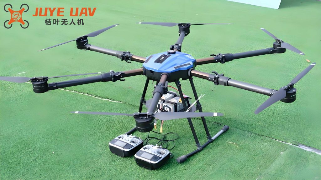
The core of this approach lies in the multirotor drone platform, which offers exceptional stability and maneuverability in complex environments. A typical multirotor drone system comprises several components: the flight platform (e.g., a quadcopter or hexacopter), navigation systems (such as GPS and IMU), flight control units, ground monitoring stations, aerial cameras, data transmission modules, and launch/recovery mechanisms. For oblique photogrammetry, the multirotor drone is equipped with multiple sensors—often five cameras angled differently—to capture images from various perspectives simultaneously. This enables the creation of realistic 3D models that incorporate precise geographic information. The terrain-following capability, or “仿地飞行” in Chinese contexts, involves generating a digital surface model (DSM) of the area, which the multirotor drone uses to maintain a constant height above ground, ensuring uniform ground sampling distance (GSD) across varying topography. This is critical for achieving consistent data quality in mountainous or uneven regions, where traditional aerial surveys might fail due to altitude fluctuations.
To implement multirotor drone terrain-following oblique photogrammetry, I follow a structured workflow that begins with site assessment and planning. First, I conduct a field reconnaissance to understand the project scope and surrounding area. This includes checking for flight restrictions using specialized software and obtaining necessary permissions. Control points are established and surveyed to georeference the data accurately. Based on project requirements, I determine the coverage area and desired GSD, which influences the choice of multirotor drone and camera. For instance, a higher GSD value might be suitable for broader overviews, while a lower GSD is essential for detailed analysis. The multirotor drone selection is crucial; I often opt for models like the DJI MATRICE series for their reliability and payload capacity. The camera parameters, such as focal length (f), sensor size, and image dimensions, are key to calculating flight parameters.
One fundamental formula I use is for the pixel size (a), which is derived from the camera’s sensor dimensions and image resolution. For a given camera, the pixel size in millimeters can be computed as:
$$ a = \frac{\text{sensor length (mm)}}{\text{image length (pixels)}} = \frac{\text{sensor width (mm)}}{\text{image width (pixels)}} $$
This leads to the calculation of the flying height (H) above ground, which ensures the desired GSD. The formula is:
$$ H = \frac{f \times \text{GSD}}{a} $$
where H is in meters, f is the focal length in millimeters, GSD is the ground sampling distance in meters, and a is the pixel size in millimeters. For example, if using a camera with a focal length of 28 mm, a sensor size of 23.5 mm × 15.6 mm, and an image resolution of 6000 × 4000 pixels, the pixel size a would be approximately 0.00392 mm. Assuming a GSD of 0.032 m, the flying height H calculates to around 229 m. This height allows the multirotor drone to capture images with sufficient detail while maintaining safety.
Next, I determine the flight path parameters, including the baseline length (Bx) and route spacing (Dy), based on image overlap requirements. The forward overlap (px) and side overlap (qy) are typically set to 80% and 70%, respectively, to ensure robust 3D reconstruction. The formulas are:
$$ Bx = Lx \times (1 – px) \times \frac{H}{f} $$
$$ Dy = Ly \times (1 – qy) \times \frac{H}{f} $$
where Lx and Ly are the image dimensions in millimeters. For instance, with Lx = 23.5 mm and Ly = 15.6 mm, Bx and Dy can be computed to design efficient flight lines. The coverage area is extended beyond the target zone by at least one flight height to ensure complete data capture, which is vital for accurate modeling. Before flight, I import a pre-existing DSM or generate one using an initial flight with a different camera setup to guide the terrain-following algorithm. This preparatory step ensures that the multirotor drone adapts to elevation changes, minimizing gaps in data.
In the field, I select an optimal takeoff location that is safe and accessible. Weather conditions are critical; I prefer clear, calm days with minimal wind to reduce motion blur and ensure visibility. After assembling the multirotor drone and performing pre-flight checks, I upload the planned route to the autopilot system. The flight is conducted during midday to minimize shadows, which can affect image quality. Post-flight, I download the imagery and POS data, then assess quality based on overlap, inclination, and coverage. If issues are detected, such as gaps or blurriness, I schedule a re-flight. The data processing phase involves aerial triangulation using software like ContextCapture, where I perform relative and absolute orientation to align images with control points. This produces dense point clouds, digital elevation models (DEMs), and orthophotos, which can be used for further analysis.
To illustrate the practical application, I will describe a case study from a geohazard project involving a large-scale rockslide. The incident occurred in a steep, mountainous region, where a slope failure resulted in significant debris accumulation, blocking a vital roadway and creating a temporary dam in a river. Initial assessments were hampered by the unstable terrain, making ground surveys risky. We deployed a multirotor drone equipped with a five-lens oblique camera system to conduct terrain-following photogrammetry. The primary objectives were to generate a high-resolution 3D model, calculate the volume of displaced material, and support the design of mitigation measures, such as rockfall barriers and debris clearance.
For this project, we set a GSD of 0.032 m, requiring a flying height of approximately 229 m. The multirotor drone used was a DJI MATRICE 300 RTK, paired with a Rainpoo D3 camera. We collected over 3,000 images across multiple flights, each lasting about 80 minutes. The data was processed to create a detailed DSM and orthomosaic, which revealed the extent of the slide and identified unstable areas. Key measurements included the slope angles, fracture patterns, and volume estimates, which were derived directly from the 3D model. The multirotor drone’s ability to fly close to the terrain allowed us to capture nuances that would be missed in traditional surveys. Based on this data, we designed an emergency response plan that included controlled blasting, mechanical removal, and the installation of protective nets. Post-intervention, we repeated the multirotor drone survey to verify the effectiveness and compute the exact volume of material removed, facilitating accurate billing and reporting.
The advantages of using multirotor drone technology in such scenarios are manifold. Firstly, the multirotor drone enhances safety by eliminating the need for personnel to enter hazardous zones. Secondly, it reduces time and cost compared to ground-based methods; a task that might take days with conventional surveying can be completed in hours. Moreover, the multirotor drone’s versatility allows for adaptation to various sensors, such as thermal or multispectral cameras, for additional insights like moisture content or vegetation cover. However, challenges include regulatory compliance, weather dependencies, and the need for skilled operators. Despite this, the multirotor drone approach has proven highly effective, particularly in inaccessible areas where other methods fall short.
In terms of data analysis, the multirotor drone-derived products enable quantitative assessments through formulas and algorithms. For instance, the volume of a landslide deposit can be calculated by comparing pre- and post-event DEMs using the formula:
$$ V = \sum (A \times \Delta h) $$
where V is the volume, A is the area of each grid cell, and Δh is the height difference. This is often implemented in GIS software, leveraging the high accuracy of multirotor drone data. Additionally, slope stability analysis can incorporate parameters like friction angles and cohesion, derived from the 3D models. To summarize key parameters, I have included a table below that outlines typical values used in multirotor drone photogrammetry for geohazard projects.
| Parameter | Symbol | Typical Value | Description |
|---|---|---|---|
| Ground Sampling Distance | GSD | 0.02–0.05 m | Resolution of images on ground |
| Flying Height | H | 100–300 m | Altitude above ground for multirotor drone |
| Forward Overlap | px | 80% | Image overlap along flight path |
| Side Overlap | qy | 70% | Image overlap between adjacent paths |
| Pixel Size | a | 0.003–0.005 mm | Size of individual pixel on sensor |
Another critical aspect is the error analysis, which ensures data reliability. The accuracy of multirotor drone photogrammetry depends on factors like GPS precision, camera calibration, and control point distribution. The root mean square error (RMSE) can be computed for control points to validate the model. For example, in our case study, the RMSE was less than 0.1 m in planimetry and 0.15 m in height, meeting the standards for 1:500 scale mapping. This level of precision is achievable due to the multirotor drone’s ability to maintain consistent flight paths and the integration of RTK GPS for real-time positioning.
Looking ahead, the integration of multirotor drone technology with artificial intelligence and machine learning promises even greater advancements. For instance, automated feature extraction from multirotor drone imagery could identify cracks or deformations in near-real-time, enabling proactive hazard management. Additionally, the use of multirotor drones in swarm configurations could cover larger areas faster, enhancing scalability. In my experience, the multirotor drone has become an indispensable tool in geohazard projects, not only for data collection but also for public awareness through visualizations like 3D animations.
In conclusion, the application of multirotor drone terrain-following oblique photogrammetry in geohazard disposal projects represents a significant leap forward in geotechnical engineering. By combining agile multirotor drone platforms with advanced photogrammetric techniques, we can obtain accurate, high-resolution data in challenging environments. This methodology improves safety, efficiency, and decision-making, ultimately contributing to more resilient infrastructure and communities. As technology evolves, I anticipate that multirotor drone systems will play an even larger role in disaster management, driven by continuous improvements in sensors, algorithms, and regulatory frameworks. The multirotor drone, in particular, has demonstrated its value across numerous projects, and I highly recommend its adoption for similar applications worldwide.