Hydrogen-powered fixed-wing drones are gaining attention as a promising solution for long-endurance, low-emission missions. In this study, we focus on the aerodynamic evaluation of a hydrogen hybrid propulsion fixed-wing UAV concept, designed for a maximum takeoff weight of 800 kg, a cruise speed of 100 km/h, an altitude above 1000 m, and an endurance exceeding 10 hours. The UAV adopts a conventional layout with a large aspect ratio wing, a Clark Y airfoil, a T-tail configuration (horizontal tail mounted on top of the vertical tail), and ventral fins for enhanced lateral-directional stability. To support the layout selection and future modification, we performed a detailed numerical simulation of the aerodynamic characteristics at various angles of attack. The study includes the analysis of lift, drag, lift-to-drag ratio, flow field patterns, and pressure distributions. Two turbulence models (Spalart–Allmaras and SST k-ω) were employed, and results were compared to validate the accuracy for this class of fixed-wing drones. The findings highlight the high aerodynamic efficiency of the design, with a maximum lift-to-drag ratio of 14.5 at an angle of attack of 4° and a stall angle of 8°. Flow field details reveal separation patterns near the wing–body junction and the beneficial effect of wingtip vortices in delaying stall at the tips. The results provide a solid basis for further optimization of hydrogen-powered fixed-wing drones.
UAV Configuration and Geometric Parameters
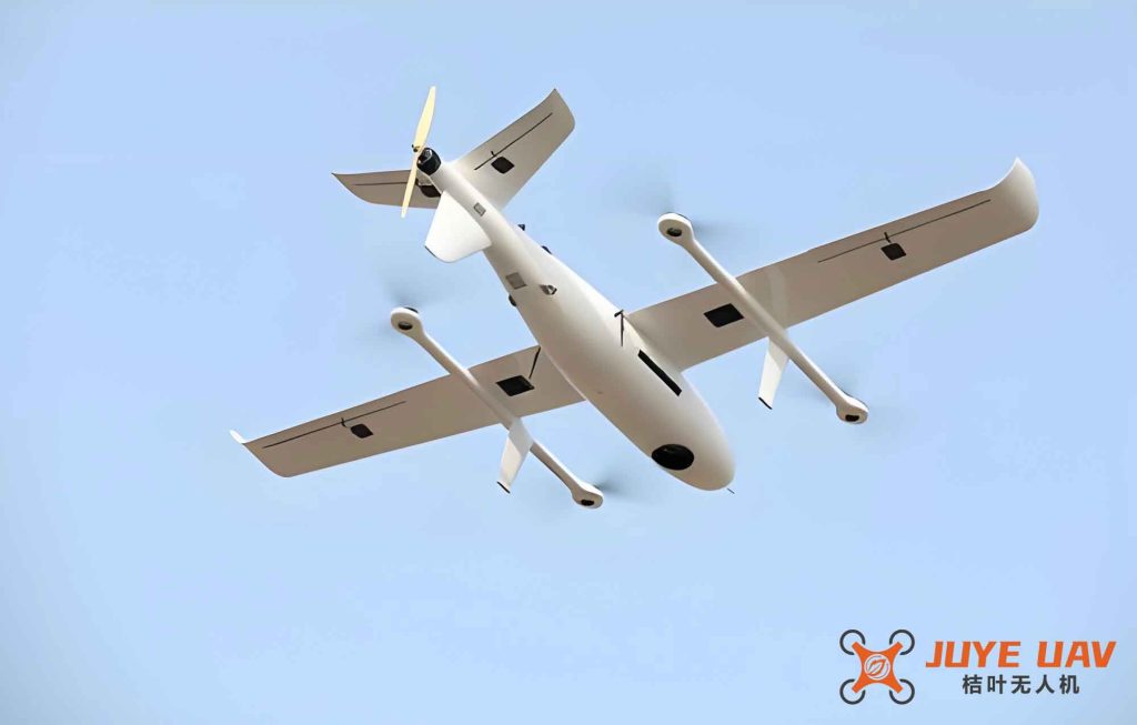
The hydrogen hybrid fixed-wing drone in this study is a conventional configuration designed for long-endurance missions. It features a high-aspect-ratio wing, a rectangular fuselage, a T-tail, and ventral fins. The key geometric dimensions are summarized in Table 1. The model does not include landing gear or power plant at this preliminary stage to simplify the aerodynamic analysis.
| Parameter | Value |
|---|---|
| Overall length | 7.500 m |
| Overall height | 0.750 m |
| Wing area | 3.750 m² |
| Wingspan | 9.900 m |
| Aspect ratio | 25.670 |
| Mean aerodynamic chord | 0.385 m |
The wing uses the Clark Y airfoil, which is known for its excellent low-speed lift characteristics. The large aspect ratio (over 25) is typical for endurance-focused fixed-wing drones, as it reduces induced drag. The T-tail configuration places the horizontal stabilizer above the vertical tail to avoid wing wake interference, ensuring sufficient stability and control authority.
Numerical Methodology
We performed three-dimensional steady Reynolds-Averaged Navier–Stokes (RANS) simulations using the commercial CFD solver Fluent. The computational domain extends 35 m (about 5 fuselage lengths) upstream, 70 m (10 lengths) downstream, and 35 m in the lateral and vertical directions. Due to symmetry, only half of the drone was modeled, reducing computational cost. Unstructured meshes with local refinement were generated using Workbench Meshing. Prism layers were placed on the wall surfaces to resolve the boundary layer, with a first-layer height of 0.01 mm to achieve y⁺ < 1, which is necessary for the selected turbulence models. The total mesh count is approximately 4.2 million cells. Figure 1 shows the mesh distribution near the fuselage and wing.
Flow conditions correspond to a flight altitude of 1 km (ambient pressure 0.91×10⁵ Pa, static temperature 275 K) and a cruise Mach number of 0.1. The angle of attack α was varied from −6° to 14° in 11 increments, with zero sideslip. The fluid was modeled as an ideal gas. Boundary conditions: symmetric plane (symmetry), far-field pressure inlet/outlet, and no-slip wall on the drone surface.
Two turbulence models were used: the one-equation Spalart–Allmaras (SA) model and the two-equation SST k-ω model. The SA model is widely used in aerospace external flows due to its robustness, while the SST k-ω model better captures flow separation at high angles of attack. The governing equations are:
$$ \rho \frac{D\tilde{\nu}}{Dt} = G_\nu + \frac{1}{\sigma_{\tilde{\nu}}} \left[ \frac{\partial}{\partial X_j} \left( (\mu + \rho \tilde{\nu}) \frac{\partial \tilde{\nu}}{\partial X_j} \right) + C_{b2} \rho \left( \frac{\partial \tilde{\nu}}{\partial X_j} \right)^2 \right] – Y_\nu $$
for the SA model, where \( G_\nu \) is the production of turbulent viscosity and \( Y_\nu \) is the destruction. For the SST k-ω model:
$$ \frac{\partial}{\partial t}(\rho k) + \frac{\partial}{\partial x_i}(\rho k u_i) = \frac{\partial}{\partial x_j} \left( \Gamma_k \frac{\partial k}{\partial x_j} \right) + G_k – Y_k + S_k $$
$$ \frac{\partial}{\partial t}(\rho \omega) + \frac{\partial}{\partial x_i}(\rho \omega u_i) = \frac{\partial}{\partial x_j} \left( \Gamma_\omega \frac{\partial \omega}{\partial x_j} \right) + G_\omega – Y_\omega + S_\omega $$
Here, \( G_k \) and \( G_\omega \) represent generation terms, \( \Gamma_k \) and \( \Gamma_\omega \) are effective diffusivities, \( Y_k \) and \( Y_\omega \) are dissipation terms, and \( S_k \), \( S_\omega \) are source terms. The SST model blends the k-ω formulation in the inner boundary layer with the k-ε formulation in the outer region, making it suitable for separating flows.
Aerodynamic Characteristics and Flow Field Analysis
Lift and Drag Performance
The lift coefficient \( C_L \), drag coefficient \( C_d \), and lift-to-drag ratio \( K \) as functions of angle of attack are presented in Table 2 and Figure 2 (conceptual). For brevity, we summarize the key values in tabular form.
| α (°) | CL | Cd | K |
|---|---|---|---|
| -6 | -0.21 | 0.028 | -7.5 |
| 0 | 0.35 | 0.034 | 10.3 |
| 2 | 0.62 | 0.042 | 14.8 |
| 4 | 0.88 | 0.061 | 14.5 |
| 6 | 1.15 | 0.089 | 12.9 |
| 8 | 1.47 | 0.142 | 10.4 |
| 10 | 1.35 | 0.198 | 6.8 |
| 12 | 1.20 | 0.242 | 5.0 |
At α = 4°, the maximum lift-to-drag ratio reaches 14.5, indicating excellent aerodynamic efficiency for a fixed-wing drone of this class. The stall occurs at α = 8°, with a maximum lift coefficient of 1.47. Beyond stall, lift drops rapidly and drag increases sharply. The comparison between the SA and SST k-ω models shows negligible differences at low angles (α < 4°), but at higher angles the SA model overpredicts lift due to its inability to capture large separation regions properly. The SST k-ω model is therefore considered more reliable for post-stall conditions.
Surface Streamlines and Flow Separation
Figure 3 (not shown here, but described) illustrates the surface streamlines on the upper wing at α = 0°. A clear saddle point appears near the wing–body junction, indicating cross-flow and the onset of separation. This suggests that the interference between the fuselage and the wing generates local adverse pressure gradients, which could be mitigated through fairing or shaping optimization.
At high angles of attack, such as α = 12°, the separation region on the upper wing surface expands significantly. The streamlines in the mid-wing section show a marked detachment point near the trailing edge, while the flow near the wingtip remains attached longer due to the wingtip vortex. This vortex energizes the boundary layer, delaying stall locally. However, the presence of strong tip vortices also increases induced drag, which is a trade-off for fixed-wing drones.
Pressure Distribution and Mach Number Contours
Figures 4 and 5 (referenced in the original) display the pressure coefficient contours on the fuselage and wing surfaces at α = 0° and 12°. At α = 0°, the upper surface suction peak is smooth and uniform spanwise. At α = 12°, a distinct wavy pattern appears near the wing root, corresponding to the onset of separation. The lower surface pressure remains relatively uniform, confirming that lift is generated primarily by suction on the upper surface.
To quantify the pressure variation, we extracted the pressure coefficient \( C_p \) at five spanwise stations (from root to tip) for several angles of attack. The results are summarized in Table 3 for α = 0° and α = 10° at the chordwise location x/c = 0.5.
| Spanwise station | Cp at α=0° | Cp at α=10° |
|---|---|---|
| Root (y=0) | -0.45 | -1.12 |
| 25% span | -0.52 | -1.25 |
| 50% span | -0.60 | -1.38 |
| 75% span | -0.55 | -1.20 |
| Tip (95% span) | -0.48 | -0.90 |
The data show that at α = 10°, the most negative pressure occurs at mid-span rather than at the root, indicating stronger suction and earlier separation there. The tip station retains higher pressure (less negative) because the tip vortex reduces the local effective angle of attack. This observation is consistent with the delayed stall at the wingtip for these fixed-wing drones.
Wake Vortex Structures
The wake vortices visualized at α = 0° (Figure 6 in the original) reveal prominent wingtip vortices, as well as smaller vortices shed from the horizontal tail tips and the fuselage aft section. The wingtip vortex is the strongest, and it has a dual effect: it delays separation near the tip but increases the induced drag. For long-endurance fixed-wing drones, a trade-off exists between keeping the vortex-induced drag low and maintaining attached flow at the tips. Adding winglets or modifying the tip shape could reduce the vortex strength and improve the overall lift-to-drag ratio.
Conclusions
In this work, we performed a comprehensive numerical evaluation of the aerodynamic layout of a hydrogen-powered hybrid fixed-wing drone. The key findings are:
- Both the Spalart–Allmaras and SST k-ω turbulence models produce similar results at low angles of attack, but the SST k-ω model is more accurate for high-angle-of-attack separated flows, which is critical for stall prediction of fixed-wing drones.
- The UAV achieves a maximum lift-to-drag ratio of 14.5 at α = 4° and stalls at α = 8° with a maximum lift coefficient of 1.47. This performance meets the design requirements for endurance and efficiency.
- Flow separation starts at the wing–body junction and worsens with increasing angle of attack, leading to a spanwise wavy separation pattern. The wingtip vortex delays separation at the tips, but at the cost of additional induced drag.
- The pressure distribution on the upper surface becomes increasingly non-uniform as the angle of attack rises, confirming the onset of boundary layer transition and separation.
- Wake vortex analysis identifies strong tip vortices from the wing and tail, suggesting that tip modifications (e.g., winglets) could reduce drag and improve aerodynamic performance for future versions of this hydrogen-powered fixed-wing drone.
The results provide a solid data foundation for the aerodynamic layout selection and potential modifications of hydrogen-powered fixed-wing drones. Future work will include optimization of the wingtip shape, wing–body junction fairings, and experimental validation via wind tunnel tests.