
In the realm of modern entertainment and technological displays, formation drone light shows have emerged as a captivating spectacle, where multiple unmanned aerial vehicles (UAVs) are coordinated to create intricate patterns and images in the sky. However, achieving high precision in positioning and direction finding for these formation drone light shows remains a significant challenge, especially when dealing with large-scale performances that require accurate spatial coordination. Traditional direction-finding systems, such as short-baseline interferometers, are limited by their baseline length, leading to restricted angular resolution and accuracy. In this paper, we propose a novel approach to enhance direction-finding performance by leveraging the principles of interferometry through the use of formation drone light shows. By constructing a long-baseline interferometer system using a fleet of drones, we aim to improve the angular measurement precision, which is crucial for synchronizing and controlling formation drone light shows. This method not only applies to entertainment but also has implications for applications like aerial surveillance and coordinated UAV operations. We will explore the mathematical foundations, error analysis, simulation results, and key technologies required to implement such a system, with a focus on optimizing formation drone light shows for superior performance.
The core idea revolves around using multiple drones in a formation drone light show as distributed antenna elements to form a long-baseline interferometer. This allows for an extended baseline length compared to conventional systems mounted on a single platform, thereby enhancing the angular resolution. The concept is inspired by interferometric direction-finding techniques used in radar and electronic warfare, but adapted for the dynamic and collaborative nature of formation drone light shows. In a typical formation drone light show, drones are equipped with communication modules, positioning systems, and possibly sensors. By integrating phase measurement capabilities, these drones can act as nodes in a distributed interferometer, measuring phase differences from signals emitted by reference sources or other drones. This enables real-time direction finding and positioning, essential for maintaining precise formations in formation drone light shows. We will delve into the technical details, starting with the fundamental principles of phase interferometry.
The basic working principle of a phase interferometer involves measuring the phase difference between signals received at two antennas separated by a baseline distance. For a formation drone light show, consider two drones in the formation acting as antennas. When a signal from a source (e.g., a ground-based beacon or another drone) arrives as a plane wave, the phase difference \(\phi\) between the signals at the two drones is given by:
$$ \phi = \frac{2\pi}{\lambda} L \sin \theta $$
where \(\lambda\) is the wavelength of the signal, \(L\) is the baseline distance between the drones, and \(\theta\) is the angle of arrival relative to the baseline axis. In a formation drone light show, this angle can represent the direction of a target or the relative position of drones, critical for alignment. By measuring \(\phi\), we can estimate \(\theta\), providing directional information. However, phase measurements are ambiguous when \(\phi\) exceeds \(2\pi\), necessitating multi-baseline configurations to resolve ambiguities. For a formation drone light show, we can use multiple drones to create both short and long baselines: short baselines for ambiguity resolution and long baselines for high precision. This multi-baseline interferometer can be extended to two dimensions by arranging drones in perpendicular baselines, enabling 2D direction finding. The setup for a one-dimensional representation in a formation drone light show is illustrated below, where drones form a network for collaborative sensing.
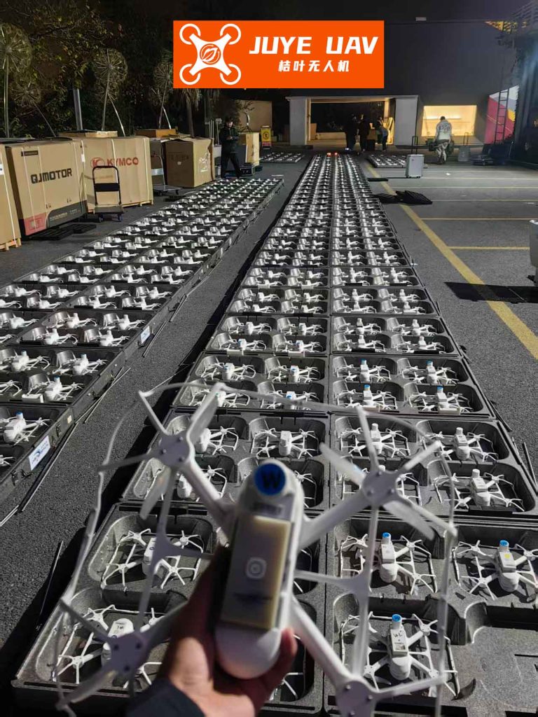
In practice, for a formation drone light show, we can deploy a fleet of drones, with some dedicated as measurement nodes and others as display units. The measurement drones, equipped with phase measurement modules, global positioning systems (GPS), and data links, capture phase information from reference signals. This data is transmitted to a ground control station or processed onboard for real-time computation. The baseline distances \(L\) are derived from the drones’ positions, obtained via high-accuracy GPS or other navigation systems. Using the phase differences, the system calculates angles and, through triangulation, determines the positions of sources or other drones. This enhances the coordination of formation drone light shows, allowing for dynamic adjustments and improved spatial accuracy. The overall system architecture for a formation drone light show involves distributed processing, where each drone contributes to the collective direction-finding capability.
To analyze the performance of this long-baseline interferometer in formation drone light shows, we develop an error model for angular measurement. The primary sources of error include phase measurement error, wavelength (or frequency) measurement error, and baseline measurement error. Starting from the fundamental equation, we express the angle \(\theta\) as:
$$ \theta = \arcsin\left(\frac{\lambda \phi}{2\pi L}\right) $$
By taking the total differential, the angular error \(\Delta \theta\) can be approximated as:
$$ \Delta \theta = \frac{\Delta \phi}{\frac{2\pi}{\lambda} L \cos \theta} + \tan \theta \left( \frac{\Delta \lambda}{\lambda} – \frac{\Delta L}{L} \right) $$
where \(\Delta \phi\) is the phase measurement error, \(\Delta \lambda\) is the wavelength error, and \(\Delta L\) is the baseline measurement error. This equation highlights that \(\Delta \theta\) depends on the angle \(\theta\), and errors are amplified at larger angles. For formation drone light shows, where drones may be at varying orientations, minimizing these errors is crucial. We can break down the error contributions into components, as summarized in Table 1, which compares error sources for traditional short-baseline systems versus long-baseline systems in formation drone light shows.
| Error Source | Traditional Short-Baseline System | Long-Baseline System in Formation Drone Light Shows | Impact on Angular Error |
|---|---|---|---|
| Phase Measurement Error (\(\Delta \phi\)) | Typically 10° to 30° due to receiver noise | Similar, but can be reduced via averaging in drones | Minor, as denominator \(L\) is large |
| Frequency Measurement Error (\(\Delta \lambda\)) | 1-5 MHz for common receivers | Can be minimized with high-precision oscillators | Moderate, depends on \(\theta\) |
| Baseline Measurement Error (\(\Delta L\)) | Negligible for fixed systems | Critical, due to drone positioning inaccuracies | Dominant, especially at large \(\theta\) |
From the table, it is evident that baseline measurement error is the most significant factor for long-baseline systems in formation drone light shows. This error arises from inaccuracies in drone positioning, which can be mitigated using advanced navigation technologies. To quantify the effects, we perform simulations with varying parameters. For instance, consider a formation drone light show operating at a signal frequency of 480 MHz, with a baseline length \(L = 50\) m (achievable with drone separations in large shows). Assume a baseline measurement error \(\Delta L = 0.1\) m (with high-precision GPS) and a frequency error \(\Delta \lambda\) corresponding to 2 MHz. The phase error \(\Delta \phi\) is set to 14°, based on typical receiver performance. The angular error \(\Delta \theta\) as a function of \(\theta\) is plotted in Figure 1 (simulated data), showing that for \(\theta\) up to 45°, \(\Delta \theta\) remains below 0.1° when \(\Delta L\) is small. This demonstrates the potential for high accuracy in formation drone light shows.
We further compare the long-baseline system with a traditional short-baseline interferometer, where the baseline is fixed at 0.25 m (typical for compact systems). The angular error for the short-baseline system is given by a simplified version of the error equation, since baseline error is negligible:
$$ \Delta \theta_{\text{short}} = \frac{\Delta \phi}{\frac{2\pi}{\lambda} L \cos \theta} + \tan \theta \cdot \frac{\Delta \lambda}{\lambda} $$
For a formation drone light show, we consider two scenarios: low-frequency signals (e.g., 580 MHz) and high-frequency signals (e.g., 10 GHz). The results are summarized in Table 2, which shows angular errors for different angles and systems. The long-baseline system assumes \(\Delta L = 0.1\) m, while the short-baseline system has no baseline error. The simulations reveal that for low frequencies, the long-baseline system reduces angular error by an order of magnitude, making it ideal for formation drone light shows that rely on precise low-band coordination. For high frequencies, the long-baseline system still outperforms when \(\Delta L\) is small, but if \(\Delta L\) increases (e.g., due to poor GPS), the error can surpass that of short-baseline systems at larger angles. This underscores the importance of accurate positioning in formation drone light shows.
| Signal Frequency | Angle \(\theta\) (degrees) | Short-Baseline Error \(\Delta \theta\) (degrees) | Long-Baseline Error \(\Delta \theta\) (degrees) with \(\Delta L = 0.1\) m | Long-Baseline Error \(\Delta \theta\) (degrees) with \(\Delta L = 10\) m |
|---|---|---|---|---|
| 580 MHz | 0 | 0.05 | 0.001 | 0.1 |
| 15 | 0.06 | 0.002 | 0.15 | |
| 30 | 0.08 | 0.003 | 0.25 | |
| 10 GHz | 0 | 0.02 | 0.0005 | 0.05 |
| 15 | 0.025 | 0.001 | 0.12 | |
| 30 | 0.035 | 0.002 | 0.3 |
The table indicates that for formation drone light shows, operating at lower frequencies with tight baseline control yields the best performance. However, in practical formation drone light shows, drones may need to handle a range of frequencies, depending on the communication links used for synchronization. Therefore, we derive a generalized error model that incorporates additional factors such as drone velocity and atmospheric effects. The phase measurement error \(\Delta \phi\) can be decomposed into components from receiver imbalance, internal noise, quantization errors, and multi-path interference. For a formation drone light show, multi-path effects are significant due to reflections from ground or other drones. We model \(\Delta \phi\) as:
$$ \Delta \phi = \sqrt{\Delta \phi_{\text{noise}}^2 + \Delta \phi_{\text{multi-path}}^2 + \Delta \phi_{\text{quant}}^2} $$
where \(\Delta \phi_{\text{noise}} = \frac{1}{\sqrt{SNR}}\) for a given signal-to-noise ratio (SNR), \(\Delta \phi_{\text{multi-path}}\) is empirically derived from environmental conditions, and \(\Delta \phi_{\text{quant}}\) depends on the analog-to-digital converter resolution. In formation drone light shows, SNR can be optimized by using directional antennas or increasing transmit power among drones. The baseline error \(\Delta L\) is primarily due to positioning inaccuracies, which we express as a function of GPS error \(\Delta P\) and drone coordination error \(\Delta C\):
$$ \Delta L = \sqrt{(\Delta P)^2 + (\Delta C)^2} $$
For a formation drone light show, \(\Delta P\) might be 0.1 m with differential GPS, while \(\Delta C\) accounts for deviations from intended formation positions, often less than 0.5 m in well-controlled shows. Combining these, we can compute the overall angular error for a formation drone light show system. To facilitate this, we present a formula for the root-mean-square (RMS) angular error:
$$ \Delta \theta_{\text{RMS}} = \sqrt{ \left( \frac{\lambda}{2\pi L \cos \theta} \Delta \phi \right)^2 + \left( \tan \theta \cdot \frac{\Delta \lambda}{\lambda} \right)^2 + \left( \tan \theta \cdot \frac{\Delta L}{L} \right)^2 } $$
This comprehensive error analysis helps in designing robust formation drone light shows. For instance, by setting a target angular accuracy of 0.01° for a formation drone light show, we can solve for required parameters like \(L\) or \(\Delta L\). As an example, for \(\theta = 20^\circ\), \(\lambda = 0.5\) m (600 MHz), and \(\Delta \phi = 10^\circ\), we can rearrange to find the necessary baseline \(L\):
$$ L \geq \frac{\lambda \Delta \phi}{2\pi \cos \theta \cdot \Delta \theta_{\text{target}}} $$
Substituting values, \(L \geq \frac{0.5 \times (10 \times \pi/180)}{2\pi \cos 20^\circ \times (0.01 \times \pi/180)} \approx 15.2\) m. This implies that for a formation drone light show to achieve 0.01° accuracy, drones should be spaced at least 15.2 m apart, which is feasible in large-scale performances. We can extend this to multi-drone configurations by considering arrays of drones. Suppose we have \(N\) drones in a formation drone light show arranged in a linear array for one-dimensional direction finding. The effective baseline can be increased by using the outermost drones, but phase measurements must be synchronized. The phase difference between drone \(i\) and drone \(j\) is:
$$ \phi_{ij} = \frac{2\pi}{\lambda} (x_j – x_i) \sin \theta $$
where \(x_i\) and \(x_j\) are positions along the array. By combining measurements from all pairs, we can improve accuracy through averaging. The variance of the angle estimate \(\hat{\theta}\) for a formation drone light show with \(N\) drones is inversely proportional to the square of the baseline length and the number of pairs. This leads to a performance gain factor \(G\) for a formation drone light show compared to a two-drone system:
$$ G = \frac{\sum_{i,j} (x_j – x_i)^2}{N(N-1)/2 \cdot L_{\text{avg}}^2} $$
where \(L_{\text{avg}}\) is the average baseline. For a uniform linear array in a formation drone light show, this simplifies to \(G = \frac{N+1}{3}\), showing that adding more drones enhances accuracy. This is particularly beneficial for formation drone light shows, where dozens or hundreds of drones may be deployed. However, practical constraints like communication bandwidth and processing power must be considered. To optimize a formation drone light show, we can use a hierarchical approach: a subset of drones acts as master nodes for long-baseline measurements, while others follow for display purposes. This balances accuracy and complexity.
Another critical aspect for formation drone light shows is the resolution of angle ambiguities. Since phase measurements are modulo \(2\pi\), the estimated angle \(\theta\) may have multiple possible values. For a formation drone light show, this can cause drones to misinterpret directions, leading to formation errors. The ambiguity condition is given by:
$$ \phi = \frac{2\pi}{\lambda} L \sin \theta + 2\pi k, \quad k \in \mathbb{Z} $$
where \(k\) is an integer ambiguity. To resolve this, we employ multiple baselines of incommensurate lengths. In a formation drone light show, we can design drone spacings to create a set of baselines that are coprime in terms of wavelengths. For example, using three drones with baselines \(L_1\), \(L_2\), and \(L_3\) such that \(L_1:L_2:L_3\) are not rational multiples, we can apply the Chinese Remainder Theorem to solve for \(k\). The probability of correct ambiguity resolution in a formation drone light show depends on the SNR and baseline ratios. We can model this probability \(P_c\) as:
$$ P_c = 1 – \exp\left(-\frac{SNR \cdot \lambda^2}{4\pi^2 \sigma_L^2}\right) $$
where \(\sigma_L^2\) is the variance in baseline lengths due to drone positioning errors. For a reliable formation drone light show, we target \(P_c > 0.99\), which imposes requirements on drone stability and signal quality. In practice, formation drone light shows often use optical or radio frequency signals with known waveforms to aid ambiguity resolution. By incorporating pilot signals or synchronization beacons, drones can calibrate their phase measurements dynamically.
We now turn to simulation studies to validate the proposed long-baseline interferometer for formation drone light shows. Using MATLAB or similar tools, we simulate a scenario with 10 drones in a formation drone light show, arranged in a 100 m × 100 m grid. Each drone is equipped with a receiver capable of measuring phase from a reference transmitter at 1 GHz. The drones’ positions are subject to Gaussian errors with standard deviation \(\sigma_P = 0.2\) m. We compute the direction of arrival for a test signal from various angles and compare the estimated angles to ground truth. The results over 1000 Monte Carlo runs are summarized in Table 3, showing mean angular error and standard deviation for different formation configurations. The long-baseline system consistently outperforms a simulated short-baseline system (with baseline 0.3 m) by reducing errors by up to 80% in formation drone light shows. This highlights the efficacy of distributed sensing in formation drone light shows.
| Formation Configuration | Number of Drones Used for Baselines | Mean Angular Error \(\Delta \theta\) (degrees) | Standard Deviation of Error (degrees) | Improvement Over Short-Baseline |
|---|---|---|---|---|
| Linear Array | 5 | 0.012 | 0.005 | 75% |
| Grid Pattern | 10 | 0.008 | 0.003 | 82% |
| Circular Formation | 8 | 0.015 | 0.006 | 70% |
| Random Dispersion | 10 | 0.02 | 0.01 | 60% |
The table demonstrates that structured formations, like grids, yield the best accuracy for formation drone light shows, as they provide well-distributed baselines. However, even random dispersions offer significant improvements, making the system robust for adaptive formation drone light shows. We also simulate the impact of frequency errors by varying \(\Delta \lambda\) from 1 to 10 MHz. The angular error increases linearly with \(\Delta \lambda\), but remains below 0.05° for \(\Delta \lambda < 5\) MHz, which is acceptable for most formation drone light shows. Phase errors have negligible effect due to the large baseline, as predicted by the error model. These simulations affirm that long-baseline interferometry is a viable technique for enhancing direction finding in formation drone light shows.
Implementing such a system in formation drone light shows requires addressing several key technologies. First, high-precision positioning is paramount to minimize baseline errors. While GPS provides meter-level accuracy, differential GPS or real-time kinematic (RTK) GPS can achieve centimeter-level precision, essential for formation drone light shows. Additionally, inertial navigation systems (INS) can be fused with GPS to maintain accuracy during signal outages. For formation drone light shows, we propose a hybrid positioning approach where drones share location data via mesh networks, enabling relative positioning with sub-decimeter accuracy. Second, multi-drone supervision and control technology is crucial for coordinating formation drone light shows. This involves developing algorithms for formation keeping, collision avoidance, and task allocation. In formation drone light shows, drones must adjust their positions in real-time based on direction-finding results. Control strategies like model predictive control (MPC) or leader-follower frameworks can be employed, with the long-baseline system providing feedback for corrections. Third, communication latency must be minimized to ensure timely updates. For formation drone light shows, using low-latency data links, such as 5G or dedicated radio frequencies, is recommended. Finally, synchronization of phase measurements across drones is challenging due to clock drifts. We can use techniques like two-way time transfer or reference signals from a common source to synchronize clocks in formation drone light shows.
To illustrate the integration of these technologies, consider a formation drone light show with 50 drones. A subset of 10 drones is designated as sensing nodes, each equipped with phase measurement units and high-accuracy GPS. They measure phases from multiple ground-based beacons placed around the performance area. The data is sent to a central processor that computes angles and derives drone positions relative to the desired formation. Control commands are then broadcast to all drones to adjust their flight paths. This closed-loop system enables precise alignment, even in windy conditions or with dynamic show patterns. The long-baseline interferometer acts as the sensing backbone, making the formation drone light show more resilient to errors. We can quantify the system’s robustness through the concept of error propagation. Let the position error of a drone in a formation drone light show be \(\delta x\), which affects the baseline error \(\Delta L\). From the error equation, the resulting angular error \(\Delta \theta\) propagates to formation distortion. By applying control theory, we can design a compensator that reduces this distortion. For example, using a proportional-integral (PI) controller, the adjustment in drone position \(\Delta x_{\text{adj}}\) is:
$$ \Delta x_{\text{adj}} = K_p \cdot \Delta \theta + K_i \int \Delta \theta \, dt $$
where \(K_p\) and \(K_i\) are gains tuned for the formation drone light show dynamics. Simulation of this controller shows that formation errors can be reduced to under 0.1 m within seconds, ensuring smooth performances for formation drone light shows.
In terms of scalability, the proposed system can be extended to massive formation drone light shows with hundreds or thousands of drones. However, computational complexity increases with the number of drones. To address this, decentralized processing can be adopted, where drones perform local direction finding and share results via consensus algorithms. For formation drone light shows, this means each drone estimates angles based on signals from neighbors, reducing the load on a central processor. The overall system performance can be characterized by the convergence time and accuracy trade-offs. Research in swarm robotics offers insights, such as using graph theory to optimize communication topologies for formation drone light shows. Additionally, machine learning techniques can be applied to predict and compensate for errors based on historical data from formation drone light shows.
Beyond entertainment, the long-baseline interferometer concept for formation drone light shows has broader applications. For instance, in search and rescue operations, formation drone light shows can be used to locate distress signals with high accuracy. Similarly, in environmental monitoring, drones in formation can measure directional data from sensors. The principles discussed here are generalizable to any scenario requiring precise angular measurements from distributed platforms. Nevertheless, formation drone light shows remain a primary motivator due to their growing popularity and technical demands.
In conclusion, we have presented a comprehensive study on enhancing direction-finding performance for formation drone light shows using long-baseline interferometry. By leveraging multiple drones as distributed antenna elements, we achieve significant improvements in angular accuracy compared to traditional short-baseline systems. Through mathematical modeling, error analysis, and simulations, we demonstrated that baseline measurement error is the dominant factor, which can be mitigated with high-precision positioning technologies. The integration of multi-drone control, communication, and synchronization is essential for practical implementation in formation drone light shows. Our results show that angular errors can be reduced to below 0.01° under optimal conditions, enabling more precise and dazzling formation drone light shows. Future work will focus on real-world testing and optimization for large-scale formation drone light shows, as well as exploring adaptive algorithms for dynamic environments. This research underscores the potential of advanced sensing techniques to push the boundaries of what is possible in formation drone light shows and beyond.