
In recent years, drone formation has emerged as a critical technology in various fields such as surveillance, logistics, and aerial displays. The ability of multiple unmanned aerial vehicles (UAVs) to maintain specific formations while tracking trajectories is essential for efficient and coordinated operations. However, achieving stable and timely formation control remains challenging due to nonlinear dynamics, external disturbances, and the need for precise convergence time. Traditional methods often lack explicit control over convergence time, which can compromise formation stability. To address this, we propose an adaptive predefined-time backstepping control strategy for drone formation, ensuring that formation errors converge within a user-defined time while robustly handling uncertainties.
Our approach integrates a predefined-time sliding mode estimator to estimate desired position information and a backstepping controller that leverages adaptive laws to counteract disturbances. This paper is organized as follows: First, we introduce the problem and system model, including mathematical preliminaries. Second, we design the formation controller with detailed derivations. Third, we present simulation results to validate our method. Throughout, we emphasize the importance of drone formation in practical applications and demonstrate how our strategy enhances performance compared to fixed-time approaches.
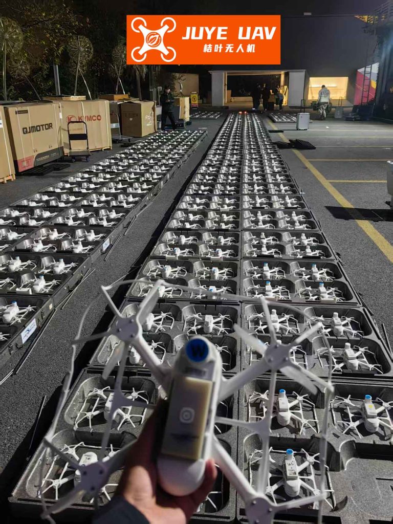
The drone formation problem involves coordinating multiple quadrotor UAVs to follow a leader’s trajectory while maintaining relative positions. Each UAV is modeled as a six-degree-of-freedom system with strong coupling between its rotational and translational dynamics. Let us consider a group of n UAVs, where the i-th UAV’s dynamics are given by Newton-Euler equations. The position dynamics in x, y, and z directions are:
$$m_i \ddot{x}_i = U_{1,i} (\cos \phi_i \sin \theta_i \cos \psi_i + \sin \phi_i \sin \psi_i) + d_{x,i},$$
$$m_i \ddot{y}_i = U_{1,i} (\cos \phi_i \sin \theta_i \sin \psi_i – \cos \phi_i \sin \psi_i) + d_{y,i},$$
$$m_i \ddot{z}_i = U_{1,i} (\cos \theta_i \cos \phi_i – m_i g_i) + d_{z,i},$$
where \(m_i\) is the mass, \(g_i\) is gravitational acceleration, \(\phi_i\), \(\theta_i\), \(\psi_i\) are roll, pitch, and yaw angles, \(U_{1,i}\) is the position control input, and \(d_{x,i}\), \(d_{y,i}\), \(d_{z,i}\) are bounded external disturbances. The attitude dynamics are:
$$\ddot{\phi}_i = \frac{l_i}{I_{x,i}} U_{2,i} + d_{\phi,i}, \quad \ddot{\theta}_i = \frac{l_i}{I_{y,i}} U_{3,i} + d_{\theta,i}, \quad \ddot{\psi}_i = \frac{l_i}{I_{z,i}} U_{4,i} + d_{\psi,i},$$
where \(l_i\) is the arm length, \(I_{x,i}\), \(I_{y,i}\), \(I_{z,i}\) are moments of inertia, \(U_{2,i}\), \(U_{3,i}\), \(U_{4,i}\) are attitude control inputs, and \(d_{\phi,i}\), \(d_{\theta,i}\), \(d_{\psi,i}\) are disturbances. We assume disturbances are bounded and vary slowly, i.e., \(\lim_{t \to \infty} \dot{d}_i = 0\).
To facilitate control, we decouple the system into an outer position loop and an inner attitude loop. The virtual control inputs \(u_x\), \(u_y\), \(u_z\) for position are derived from Eq. (14) in the original content, and the actual control inputs \(U_{1,i}\), \(\phi_{d,i}\), \(\theta_{d,i}\) are computed accordingly. For drone formation, communication topology is represented using graph theory. Let \(\mathcal{G} = (\mathcal{V}, \mathcal{E})\) be a directed graph with nodes \(\mathcal{V} = \{v_1, v_2, \dots, v_n\}\) representing UAVs and edges \(\mathcal{E} \subseteq \mathcal{V} \times \mathcal{V}\) representing communication links. The adjacency matrix \(A = [a_{ij}]\) and Laplacian matrix \(L = [l_{ij}]\) are defined as usual, and a diagonal matrix \(B = \text{diag}(b_1, b_2, \dots, b_n)\) indicates access to the leader’s trajectory, with \(b_i = 1\) if UAV i can receive leader information, else \(b_i = 0\).
Before designing the controller, we review key definitions and lemmas for predefined-time stability. These are fundamental to our drone formation strategy, ensuring convergence within a preset time.
Definition 1 (Predefined-Time Stability): The origin of a system is globally predefined-time stable if it is globally asymptotically stable and any solution \(x(t)\) reaches equilibrium within a predefined time \(T_r > 0\), independent of initial conditions.
Lemma 1: For a continuous Lyapunov function \(V(\cdot)\), if its derivative satisfies:
$$\dot{V}(\cdot) \leq -\frac{1}{r T_r} \exp(V^r(\cdot)) V^{1-r}(\cdot), \quad t \in [t_0, \infty),$$
where \(r \in (0,1)\), then the origin is globally predefined-time stable within time \(T_r\).
Lemma 2: If a Lyapunov function \(V: \mathbb{R}^n \to \mathbb{R}^+ \cup \{0\}\) satisfies \(V(0)=0\), \(V(\cdot) > 0\) for all \(\cdot \neq 0\), and:
$$\dot{V} \leq -\frac{\eta}{q} \exp(\chi V^q) V^{1-q},$$
with constants \(\eta > 0\), \(\chi > 0\), \(0 < q \leq 1\), then the system is globally predefined-time stable.
Definition 2: For a vector \(x \in \mathbb{R}^n\) and constant \(h \geq 0\), define the notation \(\lVert x \rVert^h\) as \(\lVert x \rVert^h = x / \lVert x \rVert^{1-h}\) for \(h \neq 1\), extending properties for stability analysis.
Definition 3: The predefined-time function \(\Phi_{k,s}(x; T_c)\) for \(x \in \mathbb{R}^n\), with constants \(k \geq 1\), \(0 < s \leq 1/k\), and \(T_c > 0\), is:
$$\Phi_{k,s}(x; T_c) = \frac{1}{T_c k s} \exp(\lVert x \rVert^{k s}) \lVert x \rVert^{1 – k s}.$$
Its derivative is used in controller design to enforce predefined-time convergence.
Lemma 3 and Lemma 4: Provide inequalities for vector norms and sign functions, aiding in Lyapunov analysis. For instance, for \(\xi \in \mathbb{R}^n\) and constants \(f > b > 0\):
$$\lVert \xi \rVert_f \leq \lVert \xi \rVert_b \leq n^{(1/b – 1/f)} \lVert \xi \rVert_f.$$
Lemma 5: For vectors \(\xi\) and constants \(l > 0\), we have \(\xi^T \text{sign}(\xi) = \lVert \xi \rVert_1\) and \(\xi^T \lfloor \xi \rfloor^l \geq n^{-l} \lVert \xi \rVert_{l+1}^2\), where \(\lfloor \cdot \rfloor^l\) denotes a component-wise power operation with sign preservation.
These mathematical tools enable us to design controllers that guarantee drone formation within a specific time frame. Next, we detail the controller design for our drone formation strategy.
The drone formation controller consists of two main parts: a predefined-time sliding mode estimator to estimate desired states and an adaptive predefined-time backstepping controller to track trajectories. Let \(Q_i(t) = [x_i, y_i, z_i]^T\) and \(v_i(t) = [\dot{x}_i, \dot{y}_i, \dot{z}_i]^T\) be the position and velocity of UAV \(i\), and \(Q_0(t)\), \(v_0(t)\) be those of the virtual leader. The desired position offset for formation is \(\sigma_i = [\sigma_{x,i}, \sigma_{y,i}, \sigma_{z,i}]^T\). We define estimated desired positions \(\hat{Q}_{d,i}(t)\) and velocities \(\hat{v}_{d,i}(t)\) with errors \(\tilde{Q}_{d,i} = \hat{Q}_{d,i} – Q_{d,i} – \sigma_i\) and \(\tilde{v}_{d,i} = \hat{v}_{d,i} – v_{d,i}\).
The predefined-time sliding mode estimator is designed as:
$$\dot{\hat{Q}}_{d,i}(t) = \hat{v}_{d,i}(t) + \alpha(t) H_{Q,i}(t)^{1-2p} – \alpha_1 \text{sign}(H_{Q,i}(t)),$$
$$\dot{\hat{v}}_{d,i}(t) = \beta(t) H_{v,i}(t)^{1-2p} + \delta \text{sign}(H_{v,i}(t)),$$
where \(H_{Q,i}(t) = [(L+B) \otimes I_n] \tilde{Q}(t)\), \(H_{v,i}(t) = [(L+B) \otimes I_n] \tilde{v}(t)\), \(p \in (0, 1/2)\), \(\alpha_1 > 0\), \(\delta\) is a bound on leader acceleration, and \(\alpha(t)\), \(\beta(t)\) are time-varying gains:
$$\alpha(t) = \frac{(\epsilon \varsigma)^{1-2p} \{ 2 \lambda_{\min}[(L+B) \otimes I_n] \}^{p-1}}{p T_{c,2}} \exp\left( \left\{ \frac{1}{2} \tilde{Q}^T(t) [(L+B) \otimes I_n] \tilde{Q}(t) \right\}^p \right),$$
$$\beta(t) = \frac{(\epsilon \varsigma)^{1-2p} \{ 2 \lambda_{\min}[(L+B) \otimes I_n] \}^{p-1}}{p T_{c,1}} \exp\left( \left\{ \frac{1}{2} \tilde{v}^T(t) [(L+B) \otimes I_n] \tilde{v}(t) \right\}^p \right).$$
Here, \(T_{c,1}\) and \(T_{c,2}\) are predefined times for velocity and position estimation convergence, and \(\epsilon, \varsigma\) are tuning parameters. Using Lyapunov analysis, we prove that \(\tilde{Q}(t)\) and \(\tilde{v}(t)\) converge to zero within \(T_{c,2}\) and \(T_{c,1}\), respectively, ensuring the estimator provides accurate desired states for drone formation.
With the estimated desired states, we design an adaptive predefined-time backstepping controller for trajectory tracking. We focus on the position control in the z-direction for illustration; similar steps apply to x, y, and attitude angles. Define the position error \(e_{z,i} = z_i – \hat{Q}_{d,i,z}\) and velocity error \(e_{zv,i} = v_{z,i} – \hat{v}_{d,i,z}\), where \(\hat{Q}_{d,i,z}\) and \(\hat{v}_{d,i,z}\) are z-components. Choose a Lyapunov function \(V_2 = \lVert e_{z,i} \rVert^{s_1}\) with \(s_1 \geq 1\). The desired virtual velocity is set as \(\hat{v}_{d,i,z} = -\Phi_{s_1,q_1}(e_{z,i}; T_{c1}) + \dot{\hat{Q}}_{d,i,z}\), where \(T_{c1} > 0\) and \(0 < q_1 < 1/(2s_1)\). Then, consider the combined Lyapunov function \(V(e_{z,i}, e_{zv,i}) = \lVert e_{z,i} \rVert^{s_1} + \lVert e_{zv,i} \rVert^{s_2}\) with \(1 \leq s_2 \leq 2\). Its derivative is:
$$\dot{V}(e_{z,i}, e_{zv,i}) = -s_2 \frac{e_{z,i}}{\lVert e_{z,i} \rVert^{2-s_1}} \Phi_{s_1,q_1}(e_{z,i}; T_{c1}) + s_1 \frac{e_{z,i}}{\lVert e_{z,i} \rVert^{2-s_1}} e_{zv,i} + s_2 \frac{e_{zv,i}}{\lVert e_{zv,i} \rVert^{2-s_2}} \left( \frac{U_{1,i} \cos \theta_i \cos \phi_i}{m_i} – g_i + d_{z,i} + \frac{d\Phi_{s_1,q_1}(e_{z,i}; T_{c1})}{dt} – \dot{\hat{v}}_{d,i,z} \right).$$
To achieve stability, we design the control input \(U_{1,i}\) with an adaptive law for disturbance estimation. Let \(\hat{d}_{z,i}\) be the estimate of \(d_{z,i}\), with error \(\tilde{d}_{z,i} = d_{z,i} – \hat{d}_{z,i}\). The adaptive law is \(\dot{\hat{d}}_{z,i} = s_2 \frac{e_{zv,i}}{\lVert e_{zv,i} \rVert^{2-s_2}} \lambda_z\), where \(\lambda_z > 0\) is an adaptive gain. Then, the control input becomes:
$$U_{1,i} = \frac{m_i}{\cos \phi_i \cos \theta_i} \left( g_i – \frac{d\Phi_{s_1,q_1}(e_{z,i}; T_{c1})}{dt} + \dot{\hat{v}}_{d,i,z} – \hat{d}_{z,i} – \frac{s_1}{s_2} \frac{e_{zv,i} e_{z,i}}{\lVert e_{zv,i} \rVert^{2-s_2} \lVert e_{z,i} \rVert^{2-s_1}} e_{zv,i} – \Phi_{s_2,q_2}(e_{zv,i}; T_{c2}) \right),$$
where \(T_{c2} > 0\) and \(0 < q_2 < 1/s_2\). Substituting this into \(\dot{V}\) and including a term for disturbance error, we construct a Lyapunov function \(V_{2,1} = V(e_{z,i}, e_{zv,i}) + \frac{\tilde{d}_{z,i}^2}{2\lambda_z}\). Its derivative yields:
$$\dot{V}_{2,1} \leq -s_2 \frac{e_{z,i}}{\lVert e_{z,i} \rVert^{2-s_1}} \Phi_{s_1,q_1}(e_{z,i}; T_{c1}) – s_2 \frac{e_{zv,i}}{\lVert e_{zv,i} \rVert^{2-s_2}} \Phi_{s_2,q_2}(e_{zv,i}; T_{c2}) < 0,$$
proving predefined-time stability for the z-direction position error. Similarly, for x and y directions, control inputs \(U_{x,i}\) and \(U_{y,i}\) are derived, and for attitude control, inputs \(U_{2,i}\), \(U_{3,i}\), \(U_{4,i}\) are designed using analogous steps with parameters \(a_1, a_2, p_1, p_2, T_{c3}, T_{c4}\). The overall control scheme ensures that all tracking errors converge to zero within predefined times, facilitating robust drone formation.
To validate our drone formation strategy, we conduct simulations in MATLAB/Simulink with four quadrotor UAVs. The UAV parameters are listed in Table 1, and initial conditions in Table 2. The leader’s reference trajectory is set as \(x = 10 \sin(0.2t)\), \(y = 20 \sin(0.2t)\), \(z = 10\), and \(\psi = \sin(0.1t)\). External disturbances are injected as random signals with amplitudes 0.3, 0.4, 0.5 in x, y, z directions at frequency \(1/(20\pi)\). The communication topology follows a directed graph where UAVs 1 and 4 receive leader information, with Laplacian \(L\) and matrix \(B\) as:
$$L = \begin{bmatrix} 2 & -1 & 0 & -1 \\ -1 & 2 & -1 & 0 \\ 0 & -1 & 2 & -1 \\ -1 & 0 & -1 & 2 \end{bmatrix}, \quad B = \text{diag}[1, 0, 0, 1].$$
Controller parameters are: \(s_1 = 2\), \(q_1 = 1/6\), \(s_2 = 2.5\), \(q_2 = 1/12\), \(T_{c1} = 1.5\), \(T_{c2} = 1.5\), \(a_1 = 2\), \(p_1 = 1/6\), \(T_{c3} = 1.5\), \(a_2 = 2\), \(p_2 = 1/8\), \(T_{c4} = 1.5\), and estimator parameters \(\epsilon = 0.20\), \(\varsigma = 0.15\), \(T_{c5} = 0.1\), \(T_{c6} = 0.7\).
| Parameter | Value |
|---|---|
| Mass \(m_i\) (kg) | 0.8000 |
| Moment of inertia \(I_{x,i}\) (kg·m²) | 0.0075 |
| Moment of inertia \(I_{y,i}\) (kg·m²) | 0.0075 |
| Moment of inertia \(I_{z,i}\) (kg·m²) | 0.0130 |
| Arm length \(l_i\) (m) | 0.2300 |
| UAV | Initial Position [x, y, z]ᵀ | Initial Velocity [v_x, v_y, v_z]ᵀ (m/s) |
|---|---|---|
| 1 | [-2, 1, 1]ᵀ | [1, 1, 1]ᵀ |
| 2 | [1, 2, 1]ᵀ | [1, 1, 1]ᵀ |
| 3 | [2, -1, 1]ᵀ | [1, 1, 1]ᵀ |
| 4 | [4, 1, 1]ᵀ | [1, 1, 1]ᵀ |
The simulation results demonstrate effective drone formation. As shown in the trajectory plot, all UAVs converge to the leader’s path within approximately 3.8 seconds, maintaining a diamond-shaped formation. The position and attitude tracking errors rapidly decrease to zero within the predefined times, confirming the controller’s efficacy. For instance, the z-direction position error converges in under 2 seconds, and attitude errors in about 0.45 seconds, outperforming fixed-time methods.
To highlight the advantages of our predefined-time approach for drone formation, we compare it with a fixed-time sliding mode estimator from the literature. Using the same parameters and simulation setup over 30 seconds, we observe that the fixed-time controller takes about 1 second for attitude error convergence and 5 seconds for position error, whereas our method achieves convergence in 0.45 seconds and 2 seconds, respectively. This shows that our drone formation strategy offers faster and more predictable convergence, with fewer tuning parameters. The adaptive laws effectively compensate for disturbances, as seen in the stable error profiles. Table 3 summarizes the convergence times for key errors, underscoring the benefits of predefined-time control in drone formation scenarios.
| Error Type | Fixed-Time Method (s) | Our Predefined-Time Method (s) |
|---|---|---|
| Attitude Tracking Error | ~1.0 | ~0.45 |
| Position Tracking Error | ~5.0 | ~2.0 |
| Formation Establishment Time | ~5.5 | ~3.8 |
The superior performance is attributed to the predefined-time functions \(\Phi_{k,s}(x; T_c)\) that explicitly govern convergence time, unlike fixed-time methods where bounds depend on initial conditions. Moreover, the adaptive mechanisms enhance robustness, making our drone formation strategy suitable for real-world applications with uncertainties.
In conclusion, we have presented an adaptive predefined-time backstepping control strategy for drone formation, addressing trajectory tracking with guaranteed convergence within user-defined times. The integration of a sliding mode estimator and backstepping controller, coupled with adaptive laws for disturbance rejection, ensures stable and timely formation control. Simulations validate that our approach outperforms fixed-time methods in convergence speed and robustness, making it a practical solution for drone formation tasks. Future work may extend this to heterogeneous UAVs or three-dimensional formations under communication constraints. Ultimately, this research advances drone formation technology by providing a tunable and reliable control framework.
Throughout this paper, we have emphasized the importance of drone formation in modern systems, and our method contributes to safer and more efficient multi-UAV operations. By leveraging predefined-time stability concepts, we offer a versatile tool for engineers and researchers designing coordinated drone systems. The mathematical rigor, combined with simulation evidence, underscores the potential of this strategy in real-world drone formation applications, from aerial shows to search-and-rescue missions.