
The spectacle of a synchronized formation drone light show represents a pinnacle of multi-agent coordination, transforming the night sky into a dynamic, luminous canvas. As the scale and complexity of these aerial displays grow, involving hundreds or even thousands of drones in tight formations, ensuring safe and reliable intra-formation operations becomes paramount. Traditional radio frequency (RF) communication, while effective, faces significant challenges in dense, dynamic environments due to potential interference, spectrum congestion, and susceptibility to jamming—concerns not just for entertainment but critically for analogous military or secure civilian swarm applications. This paper explores an alternative communication paradigm, proposing and analyzing a robust cooperative obstacle avoidance algorithm for drones within a formation, utilizing the unique properties of wireless ultraviolet (UV) light. Our work specifically aims to enhance the safety and resilience of large-scale formation drone light show operations and related swarm applications.
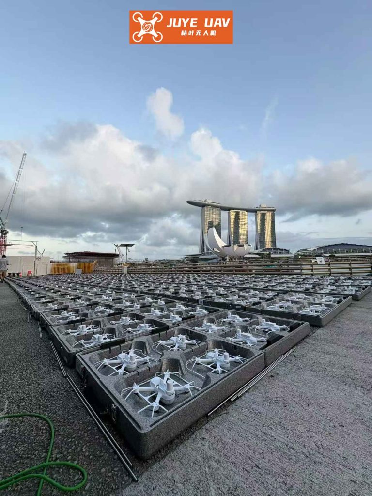
The core challenge in a high-density formation drone light show is maintaining safe inter-drone separation while executing precise, time-coordinated maneuvers. Each drone is not merely a light source but an autonomous agent navigating a constantly changing 3D space populated by its neighbors. The communication backbone for such a swarm must be low-latency, reliable, and inherently local to facilitate real-time state exchange for collision avoidance. Wireless “solar-blind” UV communication, operating in the 200-280 nm wavelength band, offers a compelling solution. Solar-blind UV light is almost completely absorbed by the ozone layer, resulting in a very low natural background at ground level. This allows for sensitive detection and provides key advantages: significant resistance to electromagnetic interference (EMI), non-line-of-sight (NLOS) capability due to atmospheric scattering, and a high degree of spatial confinement that naturally limits communication range, ideal for local swarm interactions. These features are crucial for a formation drone light show operating in electromagnetically noisy urban environments or under strict radio silence conditions in defense scenarios.
We present a novel cooperative obstacle avoidance algorithm designed for drone swarms utilizing UV communication. The algorithm integrates a UV-based virtual fencing strategy for proximity awareness, an improved cost function within an Enhanced Vector Field Histogram (VFH*) framework for smooth local replanning, and an Unscented Kalman Filter (UKF) predictor for estimating neighboring drones’ future states. This integrated approach ensures that a formation drone light show can maintain its integrity and visual flow even when executing complex, close-proximity avoidance maneuvers. The performance of our algorithm, termed the UV-Assisted Vector Field (UAVF) method, is validated through simulation and compared against established methods.
System Architecture and UV Virtual Fence Strategy
The foundation of our cooperative system is the UV Virtual Fence. Each drone is equipped with a UV LED array capable of emitting at multiple distinct wavelengths and a corresponding UV-sensitive photodetector. The communication and sensing zone around each drone is conceptually divided into three concentric spherical regions, each associated with a specific UV wavelength. This structure creates a dynamic, communication-based awareness field essential for managing a formation drone light show.
| Zone Name | Radius Range | Associated Wavelength | Primary Function & Drone State |
|---|---|---|---|
| Link Establishment Zone | $0 < r \leq R_1$ | $\lambda_3$ | Initial handshake and connection protocol. |
| Communication & Awareness Zone | $R_1 < r \leq R_2$ | $\lambda_2$ | Continuous exchange of kinematic state data (position, velocity). |
| Proximity Warning Zone | $R_2 < r \leq R_3$ | $\lambda_1$ | Early warning signal, triggers state prediction and avoidance assessment. |
When a drone receives a $\lambda_1$ signal, it recognizes another drone in its Proximity Warning Zone. It then uses the kinematic data previously exchanged via $\lambda_2$ signals (or establishes a link first if needed) to predict the neighbor’s future trajectory. Based on the predicted minimum distance $d_{min}$ over a look-ahead time window $T_{la}$, the drone classifies the threat level:
- Safe Flight: $d_{min} > R_2$. The neighbor is predicted to remain outside the critical communication zone or is moving away.
- Potential Hazard: $R_1 < d_{min} \leq R_2$. The neighbor is predicted to enter the Communication Zone soon, warranting close monitoring.
- Imminent Collision Risk: $d_{min} \leq R_1$ or the current measured distance $r \leq R_1$. Immediate local path replanning (avoidance maneuver) is executed.
This strategy provides a graduated response mechanism, crucial for preventing panic maneuvers and maintaining the overall stability of the formation drone light show.
Kinematic Model and UV-Based Histogram Construction
We model each drone’s motion in a planar coordinate system for clarity, extensible to 3D. Let the world frame be $\{W\}$ and a drone’s local body frame be $\{B\}$ with origin at its center. The drone’s state at time $k$ is given by $\mathbf{x}_k = [p_x, p_y, v, \psi, \omega]^T_k$, representing north position, east position, ground speed, heading angle, and yaw rate, respectively. The discretized kinematic model is:
$$
\begin{aligned}
\mathbf{x}_{k+1} &= f(\mathbf{x}_k, \mathbf{u}_k) + \mathbf{w}_k \\
&= \begin{bmatrix}
p_{x,k} + \frac{v_k}{\omega_k}(\sin(\psi_k + \omega_k \Delta t) – \sin(\psi_k)) \\
p_{y,k} + \frac{v_k}{\omega_k}(-\cos(\psi_k + \omega_k \Delta t) + \cos(\psi_k)) \\
v_k + a_k \Delta t \\
\psi_k + \omega_k \Delta t \\
\omega_k + \dot{\omega}_k \Delta t
\end{bmatrix} + \mathbf{w}_k
\end{aligned}
$$
where $\mathbf{u}_k = [a, \dot{\omega}]^T_k$ are the acceleration and yaw acceleration control inputs, $\Delta t$ is the time step, and $\mathbf{w}_k$ is process noise. This model accounts for curved flight paths, essential for smooth avoidance in a formation drone light show.
For a drone $i$, the distance $\rho_{ij}$ to a neighboring drone $j$ is estimated via the received UV signal strength. For NLOS links, the relationship between transmitted power $P_t$, received power $P_r$, and distance is governed by a complex scattering model. A simplified approximation for the received power in the solar-blind band can be given by:
$$
P_{r}( \rho_{ij}) \approx \frac{P_t A_r \eta_t \eta_r \kappa \Theta}{ \rho_{ij}^2 } \exp(-K_e \rho_{ij})
$$
where $A_r$ is the receiver aperture area, $\eta_t, \eta_r$ are transmit/receive efficiencies, $\kappa$ is a scattering coefficient, $\Theta$ is the geometric overlap function of the transmit and receive beams, and $K_e$ is the atmospheric extinction coefficient. The distance can be estimated by inverting this model or via calibrated lookup tables, providing the key input $\rho_{ij}$ for the avoidance algorithm.
The traditional VFH method builds a polar histogram around the robot, dividing the surrounding area into angular sectors $\alpha$. Each sector contains a value representing the obstacle density in that direction. We adapt this for a formation drone light show drone by defining the “obstacle” density $m(\alpha)$ not from static obstacles, but from the positions of neighboring drones, weighted by their proximity and relative velocity. The cost for direction $\alpha$ is:
$$
m(\alpha) = \sum_{j \in J_{\alpha}} C \cdot \zeta(\rho_{ij}) \cdot g(\mathbf{v}_{ij})
$$
where $J_{\alpha}$ is the set of neighbors whose bearing falls within sector $\alpha$, $C$ is a constant, $\zeta(\rho_{ij})$ is a monotonic decreasing function of distance (e.g., $\zeta = (\rho_{max} – \rho_{ij})^2$), and $g(\mathbf{v}_{ij})$ is a function increasing with the magnitude of the relative velocity vector $\mathbf{v}_{ij} = \mathbf{v}_j – \mathbf{v}_i$ projected towards drone $i$. This formulation ensures that closer and faster-approaching neighbors exert a stronger repulsive influence on the histogram, a critical safety feature for dynamic formation drone light show environments.
Trajectory Prediction via Unscented Kalman Filter
Accurate prediction of neighboring drones’ trajectories is vital for proactive avoidance. Given the nonlinear drone kinematic model, we employ an Unscented Kalman Filter (UKF) for state prediction. Each drone runs a UKF instance for every neighbor within its Communication Zone ($\lambda_2$ signal range).
The state transition function $f(\cdot)$ is as defined in the kinematic model. The measurement function $h(\cdot)$ relates the state to the measured relative range $\hat{\rho}$ and bearing $\hat{\beta}$ obtained from the UV link:
$$
\mathbf{z}_k = h(\mathbf{x}^j_k, \mathbf{x}^i_k) + \mathbf{v}_k = \begin{bmatrix}
\sqrt{(p^j_x – p^i_x)^2 + (p^j_y – p^i_y)^2} \\
\atan2((p^j_y – p^i_y), (p^j_x – p^i_x)) – \psi^i
\end{bmatrix}_k + \mathbf{v}_k
$$
where $\mathbf{v}_k$ is measurement noise. The UKF algorithm proceeds as follows:
- Initialization: Initialize state estimate $\hat{\mathbf{x}}^j_{0|0}$ and covariance $\mathbf{P}^j_{0|0}$ for neighbor $j$.
- Sigma Point Generation: At step $k-1$, generate $2L+1$ sigma points $\mathcal{X}_{l, k-1}$ around $\hat{\mathbf{x}}^j_{k-1|k-1}$, where $L$ is the state dimension.
- Prediction Step: Propagate sigma points through the state model: $\mathcal{X}^*_{l, k|k-1} = f(\mathcal{X}_{l, k-1}, \mathbf{u}^{j}_{k-1})$. Compute the predicted state mean $\hat{\mathbf{x}}^j_{k|k-1}$ and covariance $\mathbf{P}^j_{k|k-1}$ from the transformed sigma points.
- Update Step: When a new UV-based measurement $\mathbf{z}_k$ arrives, propagate the predicted sigma points through $h(\cdot)$, compute the predicted measurement mean $\hat{\mathbf{z}}_{k|k-1}$, and then perform the standard Kalman update to obtain the filtered state estimate $\hat{\mathbf{x}}^j_{k|k}$ and covariance $\mathbf{P}^j_{k|k}$.
For avoidance, we use the UKF’s prediction output $\hat{\mathbf{x}}^j_{k+1|k}$ and $\hat{\mathbf{x}}^j_{k+2|k}$ to estimate the neighbor’s position over the next two time steps. This predictive capability allows a drone in a formation drone light show to assess future conflict points rather than just reacting to current positions.
Improved Cost Function for Optimal Direction Selection
The UAVF algorithm samples a set of admissible motion primitives $(\Delta v, \Delta \omega)$ from the drone’s dynamic constraints (max/min speed, acceleration, yaw rate). For each primitive, it simulates the drone’s trajectory over a short duration $T_s$. For each point on this candidate trajectory, it calculates the combined cost from the predictive UV histogram and other strategic factors. The improved cost function $J(c)$ for candidate $c$ is:
$$
J(c) = \mu_g \cdot \sigma_g(c) + \mu_h \cdot \sigma_h(c) + \mu_d \cdot \sigma_d(c, k-1) + \mu_v \cdot \sigma_v(c) + \mu_p \cdot \sum_{t’=k}^{k+H} m(\alpha_{c}(t’))
$$
where:
- $\sigma_g(c)$: Angular deviation from the global goal direction (if any, for the show’s pattern).
- $\sigma_h(c)$: Angular deviation from the current heading (promotes smoothness).
- $\sigma_d(c, k-1)$: Angular deviation from the previous chosen direction (reduces oscillation).
- $\sigma_v(c)$: Cost inversely related to speed (encourages progress).
- $\sum m(\alpha_{c}(t’))$: Sum of predictive histogram costs along the candidate’s projected path over a horizon $H$, using UKF-predicted neighbor positions. This is the core formation drone light show safety term.
The weights $\mu_*$ prioritize these objectives. The candidate with the minimum total cost $J(c)$ is selected for execution. This multi-objective optimization balances collision avoidance with the fluid motion required for an aesthetically pleasing formation drone light show.
| Parameter | Value | Description |
|---|---|---|
| $R_1$, $R_2$, $R_3$ | 5 m, 15 m, 30 m | Virtual fence radii. |
| $v_{min}$, $v_{max}$ | 0 m/s, 10 m/s | Drone speed limits. |
| $a_{max}$, $a_{min}$ | 3 m/s², -4 m/s² | Acceleration limits. |
| $\omega_{max}$ | $\pi/4$ rad/s | Maximum yaw rate. |
| $\mu_g$, $\mu_h$, $\mu_d$, $\mu_v$, $\mu_p$ | 5, 2, 1, 1, 8 | Cost function weights. |
| UKF Process Noise $\mathbf{Q}$ | diag(0.1, 0.1, 0.05, 0.01, 0.005) | State transition noise covariance. |
| UKF Meas. Noise $\mathbf{R}$ | diag(0.5, 0.05) | Range & bearing noise covariance. |
Simulation Results and Analysis
We evaluated the UAVF algorithm in two challenging dynamic encounter scenarios common in a formation drone light show transition or error recovery phase, comparing it against the standard VFH* algorithm.
Scenario 1: Cross-Encounter. Two drones on near-collision courses perform avoidance while trying to reach opposite goals. The UAVF algorithm, with its predictive capability and smooth cost function, generated a significantly more efficient and graceful avoidance trajectory. It began turning earlier and with a wider, more constant-radius arc, minimizing deviation from the original path. In contrast, VFH* produced a later, sharper turn with a visible “kink” in the path, characteristic of reactive methods. Quantitative results are summarized below.
Scenario 2: Multi-Agent Convergence. Four drones starting from corners move towards a central point, requiring complex mutual avoidance. The UAVF algorithm successfully coordinated smooth, conflict-free paths for all agents. The paths showed no oscillatory behavior and maintained safe separation throughout. VFH* also achieved collision-free paths but with more pronounced and frequent heading adjustments, leading to less fluid overall motion.
| Metric | Scenario 1 (UAVF) | Scenario 1 (VFH*) | Scenario 2 (UAVF) | Scenario 2 (VFH*) |
|---|---|---|---|---|
| Total Path Length | 42.1 m | 44.8 m (+6.4%) | 68.3 m | 71.7 m (+5.0%) |
| Total Travel Time | 8.5 s | 9.8 s (+15.3%) | 12.2 s | 14.1 s (+15.6%) |
| Avg. Min. Separation | 6.8 m | 5.2 m | 7.1 m | 5.9 m |
| Path Smoothness (Avg. |Δω|) | 0.11 rad/s | 0.23 rad/s | 0.09 rad/s | 0.19 rad/s |
The UKF prediction accuracy was critical. In Scenario 1, the average position prediction error over a 1-second horizon was 0.31 m, with a maximum of 0.68 m, well within the safety margins defined by the virtual fence. This accurate prediction directly enabled the proactive and smooth avoidance behavior, a key requirement for a reliable formation drone light show.
Conclusion
This paper has presented a comprehensive cooperative obstacle avoidance framework for drone swarms utilizing wireless ultraviolet communication. By integrating a UV Virtual Fence for situational awareness, an Unscented Kalman Filter for trajectory prediction, and an enhanced cost function within a modified VFH navigation scheme, the proposed UAVF algorithm achieves safe, efficient, and smooth avoidance maneuvers. Simulation results demonstrate clear advantages over a standard reactive VFH* approach in terms of path length, completion time, minimum separation, and trajectory smoothness.
The implications for large-scale formation drone light show operations are significant. The system provides a robust communication and sensing layer that is inherently resistant to RF interference, enabling reliable operation in complex electromagnetic environments. The smooth, predictive avoidance ensures that the visual spectacle of the show is not disrupted by jerky, panic-induced maneuvers, even in dense formations or during unexpected flight path deviations. Future work will focus on 3D extension of the algorithm, optimizing UV hardware parameters for real-world ranges, and implementing the system on physical drone platforms to validate its performance in live formation drone light show demonstrations and other swarm applications.