
In the realm of unmanned aerial vehicles, the quadrotor drone has emerged as a versatile platform due to its exceptional maneuverability, ability to hover, and stable flight in confined spaces. From surveillance and reconnaissance to disaster monitoring and environmental surveys, the quadrotor drone offers a reliable solution for real-time target tracking. The integration of vision sensors, particularly cameras, enables the quadrotor drone to perceive and follow objects autonomously, even in low-speed and low-altitude scenarios. This capability is crucial for applications such as search and rescue, where rapid response and accurate tracking can save lives. In this article, I will delve into the design and analysis of a vision-based target tracking system for quadrotor drones, emphasizing the principles, hardware, and software components that ensure robust performance.
The core of any quadrotor drone tracking system lies in its control architecture. To achieve precise tracking, the system must dynamically adjust the drone’s attitude and position based on sensory input. The control structure typically comprises three modules: a filtering module, a backstepping control module, and a neural network module. These modules work in tandem to process data and generate control signals. For instance, the filtering module reduces noise from sensors, while the neural network adapts to changing environments. The overall control strategy employs an outer loop for position control and an adaptive control method to manage the quadrotor drone’s state, ensuring the flight path aligns with the desired trajectory. This approach minimizes tracking errors and enhances stability, even in turbulent conditions.
To understand the dynamics of a quadrotor drone, we can model its motion using Newton-Euler equations. The translational dynamics are given by:
$$
\begin{aligned}
\dot{\mathbf{p}} &= \mathbf{v} \\
m \dot{\mathbf{v}} &= m\mathbf{g} + \mathbf{R} \mathbf{T} – \mathbf{D} \mathbf{v}
\end{aligned}
$$
where \(\mathbf{p}\) is the position vector, \(\mathbf{v}\) is the velocity vector, \(m\) is the mass of the quadrotor drone, \(\mathbf{g}\) is the gravitational acceleration vector, \(\mathbf{R}\) is the rotation matrix from the body frame to the inertial frame, \(\mathbf{T}\) is the thrust vector, and \(\mathbf{D}\) is the aerodynamic drag coefficient matrix. The rotational dynamics are described by:
$$
\begin{aligned}
\dot{\mathbf{R}} &= \mathbf{R} \hat{\boldsymbol{\Omega}} \\
\mathbf{J} \dot{\boldsymbol{\Omega}} &= -\boldsymbol{\Omega} \times \mathbf{J} \boldsymbol{\Omega} + \boldsymbol{\tau}
\end{aligned}
$$
where \(\boldsymbol{\Omega}\) is the angular velocity vector, \(\hat{\boldsymbol{\Omega}}\) is the skew-symmetric matrix of \(\boldsymbol{\Omega}\), \(\mathbf{J}\) is the inertia tensor, and \(\boldsymbol{\tau}\) is the torque vector. These equations form the basis for designing control algorithms that enable the quadrotor drone to track targets accurately.
In practice, the tracking system uses a spiral tracking method to reduce errors. This involves analyzing the quadrotor drone’s trajectory and adjusting the attitude angles based on deviations. The control law can be expressed as:
$$
\mathbf{u} = \mathbf{K}_p \mathbf{e}_p + \mathbf{K}_d \dot{\mathbf{e}}_p + \mathbf{K}_i \int \mathbf{e}_p \, dt
$$
where \(\mathbf{u}\) is the control input, \(\mathbf{e}_p\) is the position error, and \(\mathbf{K}_p\), \(\mathbf{K}_d\), \(\mathbf{K}_i\) are proportional, derivative, and integral gain matrices, respectively. Adaptive control techniques further refine this by updating parameters in real-time, ensuring the quadrotor drone adapts to disturbances like wind gusts.
The overall design of the target tracking system prioritizes reliability and robustness. From a visual perspective, the system enhances control functionality by integrating multiple hardware and software modules. The key modules include a flight control board, an image transmission module, a camera, and a data transmission module. These components are strategically placed on the quadrotor drone to facilitate efficient data flow. For example, the camera captures visual data of the target, while the image transmission module wirelessly sends this data to a ground station for processing. This setup allows operators to monitor the quadrotor drone’s parameters in real-time and make adjustments as needed.
To summarize the hardware modules, consider the following table:
| Module | Function | Key Features |
|---|---|---|
| Flight Control Board | Processes sensor data and executes control algorithms | High-speed processor, multiple input/output ports |
| Camera | Captures visual information of the target | High resolution, low latency, wide field of view |
| Image Transmission Module | Wirelessly transmits video data to ground station | Long range, anti-interference, real-time streaming |
| Data Transmission Module | Sends control commands and telemetry data | Secure protocol, low power consumption |
This modular design ensures that each component of the quadrotor drone operates seamlessly, contributing to the overall tracking performance.
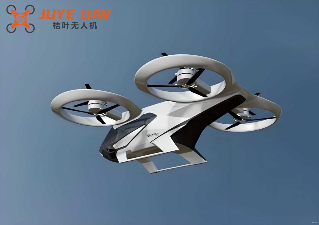
The image acquisition module is a critical aspect of the quadrotor drone tracking system. It leverages simple tool configurations and flight task planning through point-and-click interfaces, enabling cross-platform compatibility for rapid image collection. By using command-based instructions, operators can effectively control the drone’s motors and refine system functionalities via control programs. The quadrotor drone excels in image acquisition and processing, supported by remote sensing systems that enhance data capture capabilities. The image acquisition system typically includes an image capture device, a navigation device, and a trigger device. During operation, the image capture device gathers visual data of the target, while the navigation device provides spatial coordinates, accelerating the acquisition process. The trigger device, coupled with both, receives and transmits signals promptly, ensuring real-time feedback and synchronization.
In terms of hardware specifications, the image acquisition module can be characterized by parameters such as frame rate, resolution, and latency. For instance, a high-performance camera on a quadrotor drone might operate at 60 frames per second with 4K resolution, minimizing motion blur during tracking. The integration of GPS and IMU sensors further improves accuracy by correlating visual data with positional information. The following table outlines typical parameters for an image acquisition system in a quadrotor drone:
| Parameter | Value | Description |
|---|---|---|
| Frame Rate | 60 fps | Number of frames captured per second |
| Resolution | 3840 x 2160 | Pixel dimensions of the image |
| Latency | < 100 ms | Delay between capture and transmission |
| Field of View | 120 degrees | Angular extent of the captured scene |
| Sensor Type | CMOS | Image sensor technology |
These parameters ensure that the quadrotor drone can capture clear and timely images, essential for effective target tracking.
The software system plays a pivotal role in the quadrotor drone tracking system. It utilizes a receiver to acquire image data from the drone, enabling secondary development and utilization of information. In this process, the target’s location serves as a waypoint for aerial photography, and the quadrotor drone employs programming techniques to design tracking software. The target tracking workflow involves several steps: initiate tracking, hover, determine if the target is within the field of view, predict the target’s movement, assess object position, analyze tracking, handle target loss, evaluate if performance criteria are met, and conclude tracking. When the target is lost, the system employs real-time search methods to reacquire image data, identifying the target’s center position. Upon rediscovery, the system swiftly switches back to tracking mode, ensuring continuous and efficient operation.
To illustrate the tracking process mathematically, consider a state-space representation. Let \(\mathbf{x}_t\) denote the target’s state (e.g., position and velocity) and \(\mathbf{z}_t\) denote the measurement from the quadrotor drone’s sensors. The prediction and update steps in a Kalman filter, commonly used for tracking, are:
$$
\begin{aligned}
\text{Prediction:} & \quad \hat{\mathbf{x}}_{t|t-1} = \mathbf{F}_t \hat{\mathbf{x}}_{t-1|t-1} \\
& \quad \mathbf{P}_{t|t-1} = \mathbf{F}_t \mathbf{P}_{t-1|t-1} \mathbf{F}_t^T + \mathbf{Q}_t \\
\text{Update:} & \quad \mathbf{K}_t = \mathbf{P}_{t|t-1} \mathbf{H}_t^T (\mathbf{H}_t \mathbf{P}_{t|t-1} \mathbf{H}_t^T + \mathbf{R}_t)^{-1} \\
& \quad \hat{\mathbf{x}}_{t|t} = \hat{\mathbf{x}}_{t|t-1} + \mathbf{K}_t (\mathbf{z}_t – \mathbf{H}_t \hat{\mathbf{x}}_{t|t-1}) \\
& \quad \mathbf{P}_{t|t} = (\mathbf{I} – \mathbf{K}_t \mathbf{H}_t) \mathbf{P}_{t|t-1}
\end{aligned}
$$
where \(\mathbf{F}_t\) is the state transition matrix, \(\mathbf{Q}_t\) is the process noise covariance, \(\mathbf{H}_t\) is the measurement matrix, \(\mathbf{R}_t\) is the measurement noise covariance, and \(\mathbf{K}_t\) is the Kalman gain. This filter helps the quadrotor drone estimate the target’s trajectory accurately, even with noisy sensor data.
In a software design case, multithreading programming techniques are employed to enhance real-time control and safety. The software control system for the quadrotor drone comprises modules such as vision, sensor, and control modules. Each module operates in an independent sub-thread, while the main thread handles data exchange between sub-threads. This architecture allows for concurrent processing, enabling the quadrotor drone to quickly obtain attitude and position information. Sensors provide real-time data on angular velocities and accelerations along three axes, which are crucial for dynamic adjustments. For example, the sensor fusion algorithm combines data from accelerometers, gyroscopes, and magnetometers to estimate orientation. A common method is the complementary filter, given by:
$$
\hat{\theta} = \alpha (\hat{\theta}_{\text{gyro}} + \omega \Delta t) + (1 – \alpha) \theta_{\text{acc}}
$$
where \(\hat{\theta}\) is the estimated angle, \(\hat{\theta}_{\text{gyro}}\) is the gyroscope-based angle, \(\omega\) is the angular rate, \(\Delta t\) is the time step, \(\theta_{\text{acc}}\) is the accelerometer-based angle, and \(\alpha\) is a weighting factor between 0 and 1. This ensures smooth and accurate attitude estimation for the quadrotor drone.
The performance of the quadrotor drone tracking system depends on various parameters. Based on typical values, we can list key parameters that influence control effectiveness:
| Parameter | Symbol | Value | Unit |
|---|---|---|---|
| UAV Mass | \(m\) | 0.69 | kg |
| Gravitational Acceleration | \(g\) | 9.6 | m/s² |
| Arm Length | \(l\) | 0.213 | m |
| Moment of Inertia | \(J\) | 0.0055 | kg·m² |
| Aerodynamic Drag Coefficients | \(\mathbf{D}\) | (0.1, 0.1, 0.1) | N·s/m |
These parameters are used in simulation and tuning of control algorithms to optimize the quadrotor drone’s tracking capabilities. For instance, the thrust generated by each motor can be modeled as \(T_i = k \omega_i^2\), where \(k\) is a thrust coefficient and \(\omega_i\) is the motor’s angular speed. The total thrust and torques are then:
$$
\begin{aligned}
T &= \sum_{i=1}^4 T_i \\
\tau_x &= l (T_2 – T_4) \\
\tau_y &= l (T_3 – T_1) \\
\tau_z &= \sum_{i=1}^4 (-1)^{i+1} c \omega_i^2
\end{aligned}
$$
where \(c\) is a drag coefficient. This model allows for precise control of the quadrotor drone’s movements during tracking.
To enhance the system’s practicality, the design of modules like image acquisition and target tracking must be meticulous. For example, the image processing pipeline includes steps such as segmentation, feature extraction, and matching. A common technique for target detection is the use of Haar-like features with AdaBoost, which can be summarized by the classifier formula:
$$
C(\mathbf{x}) = \sum_{t=1}^T \alpha_t h_t(\mathbf{x})
$$
where \(C(\mathbf{x})\) is the strong classifier, \(h_t(\mathbf{x})\) are weak classifiers, and \(\alpha_t\) are weights determined during training. This enables the quadrotor drone to quickly identify targets in complex environments. Additionally, deep learning approaches, such as convolutional neural networks (CNNs), have been integrated into quadrotor drone systems for improved accuracy. A CNN might be represented as:
$$
\mathbf{y} = f(\mathbf{W} * \mathbf{x} + \mathbf{b})
$$
where \(\mathbf{x}\) is the input image, \(\mathbf{W}\) are convolutional filters, \(\mathbf{b}\) are biases, \(*\) denotes convolution, and \(f\) is an activation function like ReLU. These advanced methods allow the quadrotor drone to learn and adapt to varying target appearances.
In terms of system integration, the quadrotor drone tracking system must balance computational load and energy efficiency. A table comparing different tracking algorithms can help in selection:
| Algorithm | Accuracy | Computational Cost | Robustness to Occlusion |
|---|---|---|---|
| Kalman Filter | High | Low | Moderate |
| Particle Filter | Very High | High | High |
| Mean Shift | Moderate | Low | Low |
| Deep SORT | Very High | High | High |
For a quadrotor drone, algorithms with low computational cost are often preferred to conserve battery life, but accuracy cannot be compromised. Hybrid approaches, such as combining Kalman filters with neural networks, offer a balanced solution for real-time tracking.
The development of a vision-based target tracking system for quadrotor drones also involves addressing challenges like latency and communication delays. To mitigate these, the system employs predictive control strategies. For example, a model predictive control (MPC) formulation can be used:
$$
\begin{aligned}
\min_{\mathbf{u}} & \sum_{k=0}^{N-1} \left( \|\mathbf{e}_p(k)\|^2_{\mathbf{Q}} + \|\mathbf{u}(k)\|^2_{\mathbf{R}} \right) \\
\text{s.t.} & \quad \mathbf{x}(k+1) = \mathbf{f}(\mathbf{x}(k), \mathbf{u}(k)) \\
& \quad \mathbf{u}_{\min} \leq \mathbf{u}(k) \leq \mathbf{u}_{\max}
\end{aligned}
$$
where \(\mathbf{e}_p(k)\) is the tracking error at time step \(k\), \(\mathbf{Q}\) and \(\mathbf{R}\) are weighting matrices, \(N\) is the prediction horizon, and \(\mathbf{f}\) represents the quadrotor drone dynamics. This optimization ensures that the quadrotor drone anticipates future movements and adjusts controls accordingly, reducing tracking errors.
In conclusion, the design and analysis of a vision-based target tracking system for quadrotor drones involve a multifaceted approach that combines robust hardware, sophisticated software, and advanced control algorithms. The quadrotor drone’s ability to hover, maneuver precisely, and carry sensors makes it an ideal platform for applications ranging from surveillance to environmental monitoring. By leveraging modules such as image acquisition, real-time processing, and adaptive control, the system achieves high tracking performance. Key parameters, including mass, inertia, and drag coefficients, are critical for tuning and optimization. Future work may focus on integrating artificial intelligence for autonomous decision-making and enhancing energy efficiency for longer flight times. Ultimately, the goal is to create a practical and reliable system that expands the capabilities of quadrotor drones in diverse real-world scenarios.