1 Introduction
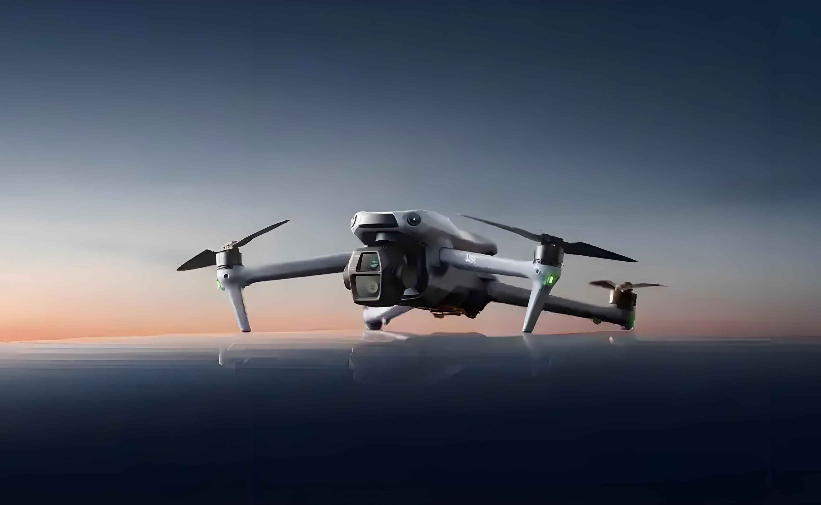
Unmanned Aerial Vehicles (UAVs), particularly quadrotors, have revolutionized aerial operations due to their compact size, vertical takeoff/landing capability, and high maneuverability. They are indispensable in military reconnaissance, infrastructure inspection, precision agriculture, and logistics. However, their operational efficacy is severely challenged by external disturbances (e.g., wind gusts) and system uncertainties (e.g., model perturbations and unmodeled dynamics). Traditional control methods, such as PID, LQR, and standard MPC, exhibit limitations in robustness and tracking accuracy under such conditions. This research addresses these gaps by proposing a novel composite control strategy integrating Tube-Based Model Predictive Control (Tube-MPC) for position tracking and Compensation Function Observer-based Model Compensation Control (CFO-MCC) for attitude stabilization. Our approach ensures precise trajectory tracking while maintaining robustness against bounded disturbances, validated through rigorous simulations and real-flight experiments.

2 Quadrotor UAV Dynamics and Modeling
The quadrotor is modeled as a rigid body with six degrees of freedom. Define the inertial frame Oe=[ex,ey,ez]TOe=[ex,ey,ez]T and body frame Ob=[bx,by,bz]TOb=[bx,by,bz]T. Key state variables include:
- Position ξ=[x,y,z]Tξ=[x,y,z]T and velocity V=[μ,v,w]TV=[μ,v,w]T in OeOe.
- Angular velocity ω=[p,q,r]Tω=[p,q,r]T and attitude angles Θ=[ϕ,θ,ψ]TΘ=[ϕ,θ,ψ]T in ObOb.
The rotation matrix Rbe∈SO(3)Rbe∈SO(3) from ObOb to OeOe is:Rbe=[cθcψsϕsθcψ−cϕsψcϕsθcψ+sϕsψcθsψsϕsθsψ+cϕcψcϕsθsψ−sϕcψ−sθsϕcθcϕcθ]Rbe=cθcψcθsψ−sθsϕsθcψ−cϕsψsϕsθsψ+cϕcψsϕcθcϕsθcψ+sϕsψcϕsθsψ−sϕcψcϕcθ
where sα=sinαsα=sinα, cα=cosαcα=cosα.
Dynamics Equations:{ξ˙=VmV˙=RbeF+G+DΘ˙=WωJω˙=−ω×Jω+τ+d⎩⎨⎧ξ˙=VmV˙=RbeF+G+DΘ˙=WωJω˙=−ω×Jω+τ+d
Here, mm is mass, J=diag(Jx,Jy,Jz)J=diag(Jx,Jy,Jz) is the inertia matrix, F=[0,0,u1]TF=[0,0,u1]T is thrust, G=[0,0,−mg]TG=[0,0,−mg]T is gravity, τ=[u2,u3,u4]Tτ=[u2,u3,u4]T is control torque, and D,dD,d are disturbance force/torque. The attitude kinematics matrix WW is:W=[1sinϕtanθcosϕtanθ0cosϕ−sinϕ0sinϕsecθcosϕsecθ].W=100sinϕtanθcosϕsinϕsecθcosϕtanθ−sinϕcosϕsecθ.
Disturbance Modeling:D=−diag(K1,K2,K3)V+σD,d=−diag(K4,K5,K6)ω+σdD=−diag(K1,K2,K3)V+σD,d=−diag(K4,K5,K6)ω+σd
where σD,σdσD,σd are bounded random disturbances satisfying ∥σD∥≤ϵD∥σD∥≤ϵD, ∥σd∥≤ϵd∥σd∥≤ϵd.
Motor Dynamics:[u1u2u3u4]=[cTcTcTcT0−dcT0dcT−dcT0dcT0cM−cMcM−cM][ϖ12ϖ22ϖ32ϖ42]u1u2u3u4=cT0−dcTcMcT−dcT0−cMcT0dcTcMcTdcT0−cMϖ12ϖ22ϖ32ϖ42
where ϖiϖi is rotor speed, cTcT is thrust coefficient, cMcM is torque coefficient, and dd is arm length.
Decoupled Subsystems:
- Position subsystem Π1Π1:{μ˙=−K1μ/m+u1x+σ1/mv˙=−K2v/m+u1y+σ2/mw˙=−K3w/m+u1z−g+σ3/m⎩⎨⎧μ˙=−K1μ/m+u1x+σ1/mv˙=−K2v/m+u1y+σ2/mw˙=−K3w/m+u1z−g+σ3/m
- Attitude subsystem Π2Π2:{p˙=((Jy−Jz)qr−K4p+σ4+u2)/Jxq˙=((Jz−Jx)pr−K5q+σ5+u3)/Jyr˙=((Jx−Jy)pq−K6r+σ6+u4)/Jz⎩⎨⎧p˙=((Jy−Jz)qr−K4p+σ4+u2)/Jxq˙=((Jz−Jx)pr−K5q+σ5+u3)/Jyr˙=((Jx−Jy)pq−K6r+σ6+u4)/Jz
3 Controller Design
3.1 Hierarchical Control Architecture
The quadrotor is underactuated, requiring a hierarchical strategy:
- Outer Loop (Position): Tube-MPC for robust trajectory tracking.
- Inner Loop (Attitude): CFO-MCC for fast disturbance rejection.
<center>
| Control Layer | Controller | Function | Output |
|---|---|---|---|
| Outer Loop | Tube-MPC | Trajectory tracking | Virtual controls (u1x,u1y,u1z)(u1x,u1y,u1z) |
| Intermediate | Attitude Solver | Compute (ϕd,θd,u1)(ϕd,θd,u1) | Desired attitude |
| Inner Loop | CFO-MCC | Attitude stabilization | Control torque ττ |
</center>
3.2 Tube-MPC Position Controller
For subsystem θxθx (x-direction dynamics):x(k+1)=Adx(k)+Bdu1x(k)+σ(k),σ(k)∈εDx(k+1)=Adx(k)+Bdu1x(k)+σ(k),σ(k)∈εD
with state x=[x,μ]Tx=[x,μ]T, constraints x∈Xx∈X, u1x∈Uu1x∈U.
Key Steps:
- Nominal Model: xˉ(k+1)=Adxˉ(k)+Bduˉ1x(k)xˉ(k+1)=Adxˉ(k)+Bduˉ1x(k).
- Error Dynamics: e(k+1)=Ade(k)+Bdu~1x(k)+σ(k)e(k+1)=Ade(k)+Bdu~1x(k)+σ(k), where e=x−xˉe=x−xˉ.
- Control Law: u1x(k)=uˉ1x(k)+u~1x(k)u1x(k)=uˉ1x(k)+u~1x(k).
- uˉ1xuˉ1x: MPC output for nominal system.
- u~1x=−Keu~1x=−Ke: Feedback gain to confine error within a robust invariant set SS.
Robust Invariant Set SS:S=AclS⊕εD,Acl=Ad−BdKS=AclS⊕εD,Acl=Ad−BdK
where ⊕⊕ denotes Minkowski sum. SS ensures e(k)∈S ∀ke(k)∈S ∀k if e(0)∈Se(0)∈S.
Constraint Tightening:xˉ∈X⊖S,uˉ1x∈U⊖(−KS)xˉ∈X⊖S,uˉ1x∈U⊖(−KS)
where ⊖⊖ is Pontryagin difference.
MPC Optimization:minUˉ(∥xˉ(Np∣k)−xd∥P2+∑i=0Np−1(∥xˉ(i∣k)−xd∥Q2+∥uˉ1x(i∣k)∥R2))Uˉmin∥xˉ(Np∣k)−xd∥P2+i=0∑Np−1(∥xˉ(i∣k)−xd∥Q2+∥uˉ1x(i∣k)∥R2)
subject to tightened constraints. The first control input uˉ1x∗(k)uˉ1x∗(k) is applied.
3.3 CFO-MCC Attitude Controller
For roll channel θϕθϕ:ϕ¨=fϕ(⋅)+bϕu2,fϕ=(Jy−Jz)qr−K4p+σ4Jx,bϕ=1Jxϕ¨=fϕ(⋅)+bϕu2,fϕ=Jx(Jy−Jz)qr−K4p+σ4,bϕ=Jx1
where fϕfϕ aggregates disturbances.
Structure:
- High-Order Differentiator (HOD):{eh=ϕd−ϕ^dv˙1=v2+l1ehv˙2=v3+l2ehv˙3=l3ehϕ^d=v1, ϕ^˙d=v2, ϕ^¨d=v3⎩⎨⎧eh=ϕd−ϕ^dv˙1=v2+l1ehv˙2=v3+l2ehv˙3=l3ehϕ^d=v1, ϕ^˙d=v2, ϕ^¨d=v3Gains: l1=3αhl1=3αh, l2=3αh2l2=3αh2, l3=αh3l3=αh3 (αh>0αh>0).
- Compensation Function Observer (CFO):{z˙1=z2+le1ecz˙2=z3+le2ec+bϕu2z˙3=le3ecϕ^=z1, p^=z2, f^ϕ=z3⎩⎨⎧z˙1=z2+le1ecz˙2=z3+le2ec+bϕu2z˙3=le3ecϕ^=z1, p^=z2, f^ϕ=z3Gains: le1=9αele1=9αe, le2=12αe2le2=12αe2, le3=4αe3le3=4αe3 (αe>0αe>0).
- Model Compensation Control Law:u2=1bϕ(kpϕ(ϕd−ϕ^)+kdϕ(ϕ^˙d−p^)+ϕ^¨d−f^ϕ)u2=bϕ1(kpϕ(ϕd−ϕ^)+kdϕ(ϕ^˙d−p^)+ϕ^¨d−f^ϕ)Gains: kpϕ=αm2kpϕ=αm2, kdϕ=2αmkdϕ=2αm (αm>0αm>0).
4 Simulation and Experimental Validation
4.1 Simulation Setup
Quadrotor Parameters:<center>
| Parameter | Value | Unit |
|---|---|---|
| Mass (mm) | 0.318 | kg |
| JxJx | 5.243×10⁻³ | kg·m² |
| JyJy | 6.933×10⁻³ | kg·m² |
| JzJz | 8.825×10⁻³ | kg·m² |
| K1−3K1−3 | 0.602 | N·s/m |
| K4−6K4−6 | 0.602 | N·m·s/rad |
</center>
Disturbances: Gaussian white noise + periodic terms, e.g., σ1=0.5sin(0.1t)+N(0,0.1)σ1=0.5sin(0.1t)+N(0,0.1).
Controllers Compared: Tube-MPC (proposed), MPC, LQR, PID.
4.2 Trajectory Tracking Performance
Reference Trajectory:
- Vertical takeoff: (0,0,0)(0,0,0) to (0,0,0.5)(0,0,0.5) m (t=0−5t=0−5 s).
- Point-to-point: (0,0,0.5)(0,0,0.5) to (2,0,0.5)(2,0,0.5) m (t=5−10t=5−10 s).
- Circular path: x=2cos(0.1π(t−10))x=2cos(0.1π(t−10)), y=2sin(0.2π(t−10))y=2sin(0.2π(t−10)), z=0.5+0.05(t−10)z=0.5+0.05(t−10) (t=10−50t=10−50 s).
- Linear motion: (0,0,2.5)(0,0,2.5) at 0.2 m/s (t>50t>50 s).
Results:
- Tube-MPC and MPC achieve lower tracking error (RMSE < 0.15 m) vs. PID/LQR (RMSE > 0.5 m).
- Tube-MPC exhibits no overshoot during turns, while MPC shows 20–30% overshoot.
- Under wind disturbances (t=60–70t=60–70 s), Tube-MPC maintains position error < 0.07 m, outperforming others by >50%.
<center>
| Controller | RMSE (m) | Max Overshoot | Settling Time (s) |
|---|---|---|---|
| Tube-MPC | 0.072 | 9.6% | 4.47 |
| MPC | 0.141 | 14.55% | 5.27 |
| LQR | 0.410 | 13.3% | 9.57 |
| PID | 0.693 | 15.2% | 10.12 |
</center>
4.3 Real-Flight Experiments
Platform: ZY-X150 quadrotor (350 g, 150 mm axis) with optical motion capture (120 Hz), RK3566 onboard computer, and PX4 flight controller.
Scenarios:
- Point Stabilization: Waypoints at (0,0,−1)(0,0,−1), (2,0,−1)(2,0,−1), (−2,0,−1)(−2,0,−1).
- Circular Trajectory: Radius = 2 m, angular velocity = 0.3 rad/s.
- Wind Disturbance: 3.5 m/s fan-induced wind during hover.
Results:
- Point Tracking: Tube-MPC reduces settling time by 25% vs. MPC and 50% vs. PX4, with near-zero overshoot.
- Trajectory Tracking: Tube-MPC achieves RMSE of 0.072 m vs. MPC (0.141 m) and PX4 (0.693 m).
- Disturbance Rejection: Tube-MPC limits position drift to 0.065 m under wind, outperforming MPC (0.175 m) and PX4 (0.264 m).
<center>
| Metric | PX4 | MPC | Tube-MPC |
|---|---|---|---|
| Position RMSE (m) | 0.693 | 0.141 | 0.072 |
| Max Wind Error (m) | 0.264 | 0.175 | 0.066 |
| Settling Time (s) | 9.89 | 5.27 | 4.47 |
</center>
5 Conclusion
This work presents a robust control framework for Unmanned Aerial Vehicles combining Tube-MPC and CFO-MCC. Key contributions include:
- Tube-MPC for position control, utilizing robust invariant sets to handle bounded disturbances while satisfying state/input constraints.
- CFO-MCC for attitude control, leveraging a compensation function observer for real-time disturbance estimation and rejection.
- Experimental Validation: The controller demonstrates superior trajectory tracking accuracy (RMSE < 0.1 m) and wind disturbance rejection (>50% improvement vs. benchmarks).
Limitations and Future Work: High-speed maneuvers induce vibrations due to control delay. Future efforts will focus on:
Extending the framework to multi-UAV cooperative tasks.
Migrating Tube-MPC to onboard hardware for higher control frequencies.
Integrating adaptive mechanisms to update model parameters and Tube sets online.
