The landscape of emergency response, particularly within fire and rescue services, is undergoing a profound transformation driven by technological innovation. Traditional firefighting tactics and equipment are increasingly challenged by the complexity of modern disaster scenarios, including high-rise fires, extensive industrial blazes, hazardous chemical incidents, and large-scale natural disasters like earthquakes and floods. In this context, the emergence and integration of Unmanned Aerial Vehicles (UAVs), specifically engineered for firefighting and rescue operations—hereafter referred to as fire UAV—have become critically important. These aerial platforms are rapidly establishing themselves as indispensable “new weapons” for contemporary fire brigades, providing crucial auxiliary support that enhances situational awareness, operational safety, and mission efficacy.
Fundamental Concepts of Fire UAVs
1.1 Definition of a UAV
A UAV, or Unmanned Aerial Vehicle, is an aircraft piloted remotely via radio control or autonomously through pre-programmed flight plans. A complete system, often termed an Unmanned Aerial System (UAS), comprises the airframe platform, the flight control system, payload equipment, and the data link/control system. Fire UAV systems are designed to perform critical functions such as reconnaissance, visual and audio data acquisition/transmission, transportation and delivery of supplies, and even direct scene intervention. They represent a convergence of multiple advanced disciplines including aeronautics, control theory, information technology, sensing, and new materials science, earning them the moniker of “aerial robots” and signaling a key direction for future aviation development.
1.2 Classification of UAVs
UAVs can be categorized based on several parameters, which is crucial for selecting the appropriate fire UAV for a specific mission.
| Classification Basis | Categories | Typical Characteristics |
|---|---|---|
| Size/Dimensions | Standard UAV (≥ 30 cm), Small UAV (100-300 cm), Ultra-Small UAV (15-100 cm), Micro UAV (≤ 15 cm) | Determines portability and operational airspace regulations. |
| Flight Mechanism | Fixed-Wing, Single-Rotor Helicopter, Multi-Rotor, Hybrid VTOL, Lighter-than-Air | Defines flight endurance, speed, hover capability, and payload capacity. Multi-rotor platforms are prevalent in fire UAV applications due to their hover stability. |
| Primary Application | Military, Civilian/Commercial | Fire UAV falls under the civilian/commercial category with specialized public safety design. |
| Production Grade | Consumer-Grade, Professional/Industrial-Grade, Custom-Built | Firefighting requires robust, reliable industrial-grade or custom-built fire UAV systems. |
Technical Advantages of Fire UAVs
The operational value of a fire UAV stems from a combination of advanced microelectronics, robust communication systems, and versatile payload integration. They offer a cost-effective means to access and monitor areas that are either too dangerous or entirely inaccessible for ground personnel, providing real-time intelligence that is vital for effective incident command.
The core technical advantages can be summarized as follows:
(1) High Portability and Ease of Operation. Modern fire UAV systems are designed for rapid deployment. Their lightweight and compact form factor allows for transportation in standard response vehicles, with setup and flight operations typically manageable by 1-2 personnel after proper training.
(2) Comprehensive Situational Awareness and Diverse Monitoring. This is arguably the most significant advantage. A fire UAV can be equipped with various sensor payloads—visible light cameras, thermal imaging cameras, gas detectors, multispectral sensors—to gather data from multiple perspectives. It provides an aerial overview that is unattainable from the ground, covering day and night operations. The data collected includes visual mapping, heat signatures for identifying fire hotspots and victims, and atmospheric measurements (temperature, humidity, wind direction, gas concentrations). This comprehensive awareness drastically reduces the blind spots inherent in ground-based reconnaissance and significantly lowers the risk to frontline responders by keeping them out of immediately hazardous zones. The relationship between sensor coverage area (A) and flight altitude (h) for a camera with a given field of view angle (θ) can be approximated by:
$$ A \approx \pi (h \cdot \tan(\frac{\theta}{2}))^2 $$
This illustrates how a fire UAV‘s visual coverage expands quadratically with altitude, providing a massive area scan advantage.
(3) Remote Command and Real-Time Data Link. The fire UAV serves as a remote sensory platform for the incident commander. High-bandwidth, low-latency video transmission systems stream live footage directly to ground control stations and mobile command posts. This enables remote piloting of the aircraft and its camera gimbal, allowing commanders to “see through the eyes” of the fire UAV from a safe distance and make informed, timely decisions based on real-time intelligence.
Applications of Fire UAVs in Firefighting and Rescue Operations
The integration of fire UAV technology directly enhances operational capabilities across various phases of a firefighting or rescue mission, particularly in complex scenarios involving high-rises, large industrial complexes, chemical plants, and special environments.
(1) All-Angle, Timely, and Effective Fireground Reconnaissance. The fire UAV acts as an airborne scout. In complex terrains like high-rise buildings or sprawling industrial facilities, it can quickly bypass ground obstacles to provide an initial assessment, pinpointing the fire’s seat, evaluating spread patterns, identifying potential water sources, and assessing structural integrity. In flammable/explosive environments, it can safely approach the core hazard area for close inspection, monitoring combustion dynamics and structural temperature to guide tactical decisions. For chemical fires, a fire UAV equipped with thermal and gas detection modules becomes essential. It can monitor tank surface temperatures to warn of imminent Boiling Liquid Expanding Vapor Explosion (BLEVE) risks, governed by principles of heat transfer. The heat flux \( q \) to a structure can be related to fire radiation:
$$ q = \epsilon \sigma (T_f^4 – T_s^4) $$
where \( \epsilon \) is emissivity, \( \sigma \) is the Stefan-Boltzmann constant, and \( T_f \) and \( T_s \) are fire and surface temperatures respectively. By measuring \( T_s \), the fire UAV provides data critical for deciding cooling strategies and safe withdrawal distances. Furthermore, for search and rescue within a fire-compromised structure, a fire UAV with a zoom camera and thermal imager can efficiently scan windows, roofs, and interior spaces through openings, locating victims faster and safer than ground teams.
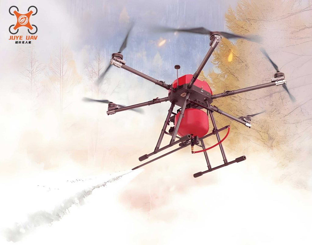
(2) Accurate and Efficient Auxiliary Rescue Support. Beyond reconnaissance, the fire UAV evolves into a multi-role support platform. In large-scale disaster zones (earthquake rubble, flood plains, landslide areas), it drastically expands search patterns and efficiency compared to ground teams. When equipped with loudspeakers, it can deliver clear instructions or calming messages to trapped individuals in situations where ground-based shouting is ineffective or where radio communication is impossible. In communications-blackout scenarios (e.g., after an earthquake), a fire UAV can act as a temporary communication relay node, restoring vital command links. Perhaps most directly, it can serve as a precision aerial delivery system. In flood, avalanche, or mountain rescue situations, traditional throwing devices are limited by range and accuracy. A fire UAV can carry and accurately drop essential survival gear—life vests, radios, ropes, medical supplies—directly to victims, accelerating rescue timelines. The required thrust \( T \) for a fire UAV to hover while carrying a payload of mass \( m_{payload} \) is given by:
$$ T = (m_{uav} + m_{payload})g $$
where \( m_{uav} \) is the mass of the UAV itself and \( g \) is gravitational acceleration. This simple formula dictates the design and capability of transport-oriented fire UAV platforms.
Future Prospects for Fire UAVs
The evolution of fire UAV technology is far from static. Current platforms, serving as “aerial scouts” and “light transports,” are the foundation for future systems that may function as true “aerial firefighting units.” We anticipate advancements in autonomous swarming for area saturation, integration of AI for real-time hazard pattern recognition, development of heavy-lift UAVs for direct fire suppression (water/foam/retardant dropping), and even UAVs capable of direct intervention, such as creating entry points or deploying extinguishing agents inside structures. The proliferation of UAV technology across industries—from cinematography and agriculture to infrastructure inspection—ensures a rapid pace of innovation that will continuously feed back into enhancing the capabilities of specialized fire UAV systems, solidifying their role as a cornerstone of modern, technology-enabled emergency response.
Analysis and Resolution of ONU Weak Light Issues in GPON Networks
Parallel to the rise of aerial platforms in public safety, the telecommunications infrastructure that often supports their data links and broader command networks is also based on advanced technology. Gigabit-capable Passive Optical Networks (GPON) form the backbone of modern broadband access, characterized by high bandwidth, long-range transmission, and multi-service convergence for residential, commercial, and backhaul applications. As network scale expands, a prevalent and impactful issue encountered in maintenance is the “weak light” condition at the Optical Network Unit (ONU), which severely degrades service quality. This analysis delves into the causes and solutions for ONU weak light, a critical concern for network stability.
Analysis of ONU Weak Light Causes
1.1 Optical Link Loss Analysis
GPON is a point-to-multipoint access technology comprising an Optical Line Terminal (OLT), ONUs, and the passive Optical Distribution Network (ODN). The system uses Wavelength Division Multiplexing (WDM) for bi-directional transmission on a single fiber: 1490 nm downstream and 1310 nm upstream. The performance is governed by the optical power budget of the transceivers.
| Optical Module Type | Component | Transmit Power (dBm) | Receive Sensitivity (dBm) | Link Budget (dB) |
|---|---|---|---|---|
| Class B+ | OLT | +1.5 to +5.0 | -8 to -28 | 13 – 28 |
| Class B+ | ONU | +0.5 to +5.0 | -8 to -27 | 13 – 28 |
| Class C+ | OLT | +3.0 to +7.0 | -12 to -32 | 17 – 32 |
| Class C+ | ONU | +0.5 to +5.0 | -8 to -30 | 17 – 32 |
Weak light occurs when the received optical power at the ONU falls below its specified sensitivity threshold, leading to high Bit Error Rate (BER) and potential link failure. The total link loss \( L_{total} \) is the sum of several factors:
$$ L_{total} = L_{fiber} + L_{splitter} + L_{connectors} + L_{splice} + L_{margin} $$
Where:
- \( L_{fiber} = \alpha \times D \), with \( \alpha \) being the fiber attenuation coefficient (e.g., ~0.36 dB/km at 1490nm) and \( D \) the fiber distance.
- \( L_{splitter} \) is the insertion loss of the optical splitter (e.g., ~3.5 dB for a 1:2 split, ~7.2 dB for 1:8, ~10.5 dB for 1:16).
- \( L_{connectors} \) accounts for losses at mechanical connection points (typically 0.3-0.5 dB per mated pair).
- \( L_{splice} \) is the loss at fusion splice points (typically < 0.1 dB per splice).
- \( L_{margin} \) is a system margin reserved for component aging and unexpected losses.
An ONU weak light condition arises when:
$$ P_{rx}^{ONU} = P_{tx}^{OLT} – L_{total} < Sensitivity_{ONU} $$
Where \( P_{rx}^{ONU} \) is the received power at the ONU and \( P_{tx}^{OLT} \) is the OLT transmit power.
1.2 Primary Contributing Factors
The main causes for weak light can be categorized as follows, often interacting cumulatively:
| Category | Specific Causes | Effect |
|---|---|---|
| Excessive Optical Path Loss | Overly long fiber routes exceeding the link budget; High split-ratio splitters (e.g., 1:64) introducing high inherent loss; Poor-quality splitters or fibers with higher-than-specified attenuation. | Directly reduces \( P_{rx}^{ONU} \) below the acceptable threshold. |
| Poor-Quality Connections & Installation | Dirty or scratched optical connectors (ferrules); Improperly seated connectors; Excessive bending of the fiber (macrobend or microbend loss). Bending loss can be approximated for a single-mode fiber as: $$ L_{bend} \propto \exp(-R/R_c) $$ where \( R \) is the bend radius and \( R_c \) is a critical radius. | Introduces high point losses or continuous attenuation, severely degrading the signal. |
| Faulty or Degraded Components | Aging OLT or ONU optical modules with reduced output power; Damaged or degraded fiber sections due to environmental stress or physical damage. | Reduces \( P_{tx} \) or increases \( L_{fiber} \), upsetting the power budget. |
Prevention and Resolution of Weak Light Issues
Addressing weak light involves a systematic approach from network design to active maintenance.
2.1 Preventive Measures in Design and Deployment
A robust design is the first defense. This involves accurate link budget calculation during planning:
$$ P_{rx}^{ONU(min)} = P_{tx}^{OLT(min)} – L_{fiber} – L_{splitter} – L_{passive\_components} – L_{margin} $$
The calculated \( P_{rx}^{ONU(min)} \) must be greater than the worst-case sensitivity of the ONU. Using higher-power Class C+ modules extends the permissible loss budget. Ensuring proper installation practices—clean connector handling, avoiding sharp bends, and using high-quality passive components—is paramount.
2.2 Diagnostic and Rectification Procedures
When a weak light alarm is reported, a structured troubleshooting process is applied:
Step 1: Remote Data Verification. Check the ONU’s received optical power value reported via the OLT management system to confirm the alarm and its severity.
Step 2: On-site Testing with an Optical Power Meter (OPM). This is the definitive step. Measure power at key points:
- At the ONU’s input port to confirm the weak light condition locally.
- At the distribution fiber output (before the drop fiber) to isolate if the issue is in the ODN or the drop segment.
- Perform a “two-ended” test using an Optical Time-Domain Reflectometer (OTDR) if a fault location is suspected. The OTDR trace will show discrete reflection events (connectors, splices) and loss points, identifying the distance to a fault. The location \( D_{fault} \) is calculated from the time delay \( \Delta t \) of the reflected pulse: $$ D_{fault} = \frac{v \cdot \Delta t}{2} = \frac{c}{n_{eff}} \cdot \frac{\Delta t}{2} $$ where \( v \) is the speed of light in the fiber, \( c \) is the vacuum speed of light, and \( n_{eff} \) is the fiber’s effective refractive index.
Step 3: Rectification. Based on diagnostics:
- If connectors are dirty, clean them with approved tools and materials.
- If a connector is damaged, re-terminate the fiber or replace the patch cord.
- If a splice or a fiber section is faulty, perform a re-splice or replace the damaged fiber segment.
- If the total path loss is simply too high due to distance/split ratio, consider network re-engineering: adding an optical amplifier (in rare cases), using a lower split-ratio, or deploying an intermediate active node.
A summary of the rectification logic is presented below:
| Diagnosed Cause | Recommended Action | Expected Outcome |
|---|---|---|
| Dirty/Contaminated Connectors | Professional cleaning of all connector end-faces in the path. | Restoration of 0.5-2.0 dB of loss per connection. |
| Failed Connector or Patch Cord | Replacement of the faulty connector or entire patch cord. | Elimination of a high-point loss source. |
| Excessive Fiber Bend | Straightening the fiber route, removing tight bends. | Reduction of continuous or localized bending loss. |
| High Splice Loss or Fiber Break | Re-splicing or splicing in a new fiber section. | Restoration of continuity and low-loss path. |
| Inherent Link Budget Exceeded | Network redesign: Use higher-power optics, reduce split ratio, or shorten distance. | Fundamental resolution of the power budget deficit. |
In conclusion, just as the effective deployment of a fire UAV relies on understanding its technical parameters and operational limits, maintaining high-quality GPON service depends on a rigorous comprehension of its optical power budget. Proactive design, careful installation, and a methodical approach to diagnosing and fixing weak light issues are essential for ensuring the reliability of the telecommunications infrastructure that supports modern emergency services and broader digital society. Both fields underscore the critical importance of applied technology and systematic problem-solving in mission-critical environments.