
The imperative for precise and efficient monitoring of structural deformations throughout the lifecycle of construction projects has never been greater. As architectural endeavors push the boundaries of height and span, the limitations of conventional survey methods—such as total stations and GNSS—become increasingly apparent, particularly concerning their labor intensity, environmental sensitivity, and temporal resolution. The advent of drone-based surveying technology heralds a paradigm shift, introducing a powerful toolset for high-frequency, high-resolution, and highly adaptable data acquisition. This article, from the perspective of a practitioner and researcher in the field, delves into the application of drone surveying in construction engineering deformation monitoring. It explores the fundamental principles, outlines its transformative significance, and proposes concrete application strategies, with a recurring emphasis on the critical role of systematic drone training in ensuring operational excellence and data reliability.
The core of drone surveying lies in its ability to act as a versatile aerial platform for remote sensing payloads. Principally, it employs two complementary technologies: Photogrammetry and Light Detection and Ranging (LiDAR). Aerial photogrammetry, often executed in an oblique imaging mode with high overlap (e.g., 80% front lap and 70% side lap), reconstructs 3D geometry through Structure from Motion (SfM) algorithms. The process begins with feature detection and matching across multiple overlapping images. Through bundle adjustment, the precise exterior orientation (position and attitude) of each image and the 3D coordinates of the tie points are solved simultaneously. The fundamental equation governing the collinearity condition in photogrammetry is expressed as:
$$ x – x_0 = -f \frac{m_{11}(X – X_0) + m_{12}(Y – Y_0) + m_{13}(Z – Z_0)}{m_{31}(X – X_0) + m_{32}(Y – Y_0) + m_{33}(Z – Z_0)} $$
$$ y – y_0 = -f \frac{m_{21}(X – X_0) + m_{22}(Y – Y_0) + m_{23}(Z – Z_0)}{m_{31}(X – X_0) + m_{32}(Y – Y_0) + m_{33}(Z – Z_0)} $$
where $(x, y)$ are image coordinates, $(x_0, y_0, f)$ are interior orientation parameters, $(X, Y, Z)$ are object space coordinates, $(X_0, Y_0, Z_0)$ are perspective center coordinates, and $m_{ij}$ are elements of the rotation matrix. This process yields dense point clouds, digital surface models (DSMs), and photorealistic 3D meshes. Conversely, LiDAR sensors actively emit laser pulses and measure their time-of-return, directly generating highly accurate 3D point clouds, effective even in low-light conditions and capable of penetrating vegetation to some degree. The integration of Real-Time Kinematic (RTK) or Post-Processed Kinematic (PPK) GNSS receivers with Inertial Measurement Units (IMUs) is crucial, providing georeferenced accuracy at the centimeter level. This fusion of technologies enables the creation of a precise digital twin of the structure, which serves as the baseline for deformation analysis.
The application of this technology is fundamentally reshaping deformation monitoring practices. Its foremost contribution is the dramatic enhancement of measurement precision and spatial resolution. Traditional methods provide discrete point-based data, potentially missing critical deformation patterns between measurement stations. Drone surveying offers a continuous, area-based assessment. By comparing multi-epoch point clouds using algorithms like the Iterative Closest Point (ICP), sub-centimeter and even millimeter-level displacements can be detected across the entire structure’s surface. The ICP algorithm minimizes the error metric $E(R, t)$:
$$ E(R, t) = \sum_{i=1}^{N} \sum_{j=1}^{M} w_{ij} \lVert m_i – (R s_j + t) \rVert^2 $$
where $R$ is the rotation matrix, $t$ is the translation vector, $m_i$ are points from the model cloud, $s_j$ are points from the scene cloud, and $w_{ij}$ is a weight for correspondence. This allows for the identification of differential settlement, torsional bending, and the initiation and propagation of cracks with unprecedented detail. Secondly, operational efficiency is vastly improved. A single automated drone flight can capture data from vast or inaccessible areas in a fraction of the time required for ground-based surveys. This enables high-frequency monitoring campaigns—daily, weekly, or monthly—providing a dynamic, temporal view of structural behavior during critical construction phases or in response to environmental loads. Finally, it acts as a catalyst for digital transformation in the Architecture, Engineering, and Construction (AEC) industry. The rich, spatially explicit data feeds directly into Building Information Modeling (BIM) workflows, facilitates progress tracking, supports forensic analysis, and underpins the development of predictive maintenance models, thereby enhancing decision-making across the project lifecycle.
| Aspect | Traditional Surveying (Total Station/GNSS) | Drone-Based Surveying |
|---|---|---|
| Data Type | Discrete point measurements | Continuous area/volume (Point Cloud, Mesh) |
| Spatial Resolution | Low (defined by instrument setup) | Very High (1-5 cm/pixel or 100-500 pts/m² common) |
| Coverage Speed | Slow, labor-intensive | Rapid (hectares per flight) |
| Accessibility | Limited by terrain and safety | Excellent for roofs, facades, hazardous zones |
| Data Output | Coordinate lists, 2D profiles | 3D Models, DSMs, DTMs, Orthomosaics, Volumetric data |
| Frequency | Low, due to cost and time | High, enabling time-series analysis |
To harness these benefits effectively, a multi-faceted application strategy must be implemented. The cornerstone is a Multimodal Synergistic Data Acquisition Strategy. The selection of platform and sensor must be mission-specific. A comparative matrix for sensor selection is presented below:
| Monitoring Objective | Primary Sensor | Key Metric | Advantages |
|---|---|---|---|
| General Deformation / Volumetric | High-Res RGB Camera (Oblique) | Ground Sample Distance (GSD) | Cost-effective, color/texture data, good for visual inspection. |
| Crack Detection & Material Stress | Multispectral / Thermal Camera | Spectral Band Resolution | Detects moisture, thermal anomalies, and material degradation invisible to RGB. |
| High-Precision Deformation (e.g., Bridges) | LiDAR | Point Density, Absolute Accuracy | Highly accurate 3D points, less affected by lighting, can filter vegetation. |
| Rapid, Large-Area Topography | Fixed-Wing UAV with RGB | Coverage Area per Flight | Long endurance, efficient for linear infrastructure or large sites. |
Flight planning parameters are critical. For photogrammetry, achieving a GSD suitable for detecting target deformations is paramount. The required flight altitude $H$ can be derived from: $GSD = \frac{H \times p}{f}$, where $p$ is the sensor pixel size and $f$ is the focal length. Overlap parameters (often >80% front, >70% side) must be strictly adhered to ensure robust 3D reconstruction. For deformation studies, the use of highly stable Ground Control Points (GCPs) or RTK/PPK is non-negotiable for minimizing systematic errors and enabling accurate multi-epoch alignment.
The second pillar is an Intelligent Data Processing and Analysis Pipeline. Raw data undergoes a sequenced transformation. For imagery, this involves aerial triangulation, dense image matching, and georeferencing. For LiDAR, point cloud classification and filtering are essential. The core of deformation analysis lies in the co-registration of point clouds from different epochs ($T_1$, $T_2$, … $T_n$). After registration, change detection algorithms quantify displacement. A simple vertical displacement $d_z$ for a point $i$ between two epochs is: $d_{z,i} = Z_{i,T2} – Z_{i,T1}$. However, more sophisticated vector analysis is standard. The workflow can be summarized as:
| Processing Stage | Core Tasks | Typical Software/Algorithm | Quality Check |
|---|---|---|---|
| Data Ingestion & Alignment | Import images/LiDAR, apply GNSS/IMU data, organize by epoch. | Pix4D, Agisoft Metashape, Bentley ContextCapture | Check image quality, GNSS coverage. |
| 3D Reconstruction / Point Cloud Generation | SfM processing, bundle adjustment, dense matching or direct LiDAR point cloud processing. | SfM Algorithms, PMVS, CMPMVS | Reprojection error < 0.5 pixels, point cloud density. |
| Georeferencing & Model Export | Scale and orient model using GCPs or RTK data, generate DEM/DSM, orthomosaic, textured mesh. | Least Squares Adjustment | GCP Root Mean Square Error (RMSE) in X,Y,Z. |
| Multi-Epoch Alignment (Registration) | Align all epoch models to a common stable coordinate system using ICP or feature-based methods. | Iterative Closest Point (ICP) Algorithm | Registration error (e.g., Cloud-to-Cloud distance). |
| Change Detection & Analysis | Calculate differential surfaces (DoD), extract displacement vectors, identify and measure cracks. | M3C2 algorithm, raster differencing, machine learning classifiers for crack detection. | Statistical significance of detected changes (e.g., threshold based on precision). |
| Visualization & Reporting | Generate displacement heatmaps, time-series graphs, annotated 3D views, and automated reports. | CloudCompare, GIS Software, Python/Matlab | Clarity and accuracy of final deliverables. |
The final and often most overlooked strategic component is the Establishment of a Standardized Operational Framework and a Rigorous Drone Training Regimen. Technology is only as good as its operators. A comprehensive framework must encompass:
- Mission Planning Protocols: Checklists for pre-flight site assessment, risk analysis, weather evaluation, and regulatory compliance (airspace authorization).
- Standard Operating Procedures (SOPs): Detailed, repeatable procedures for specific monitoring tasks (e.g., “Monthly Dam Inspection SOP”), covering everything from equipment setup to data backup.
- Data Management and Security Policy: Protocols for data ingestion, storage, version control, archival, and sharing, ensuring integrity and traceability.
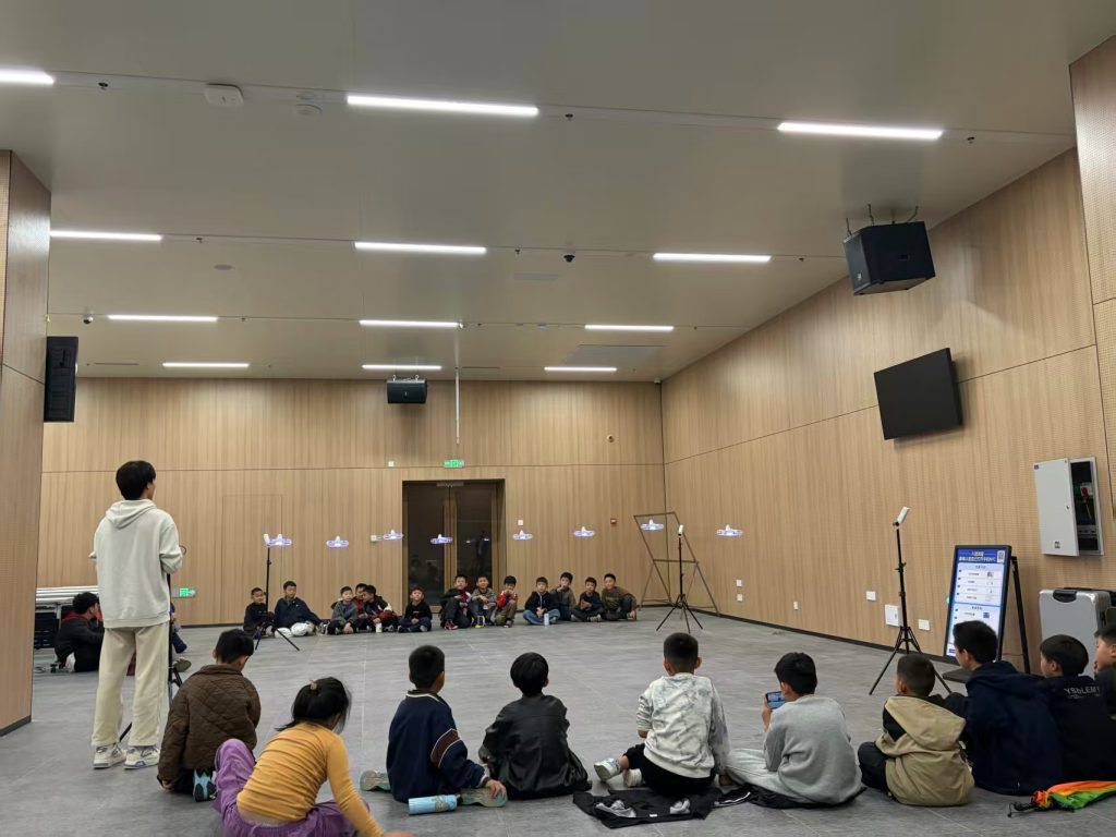
Underpinning this framework is systematic drone training. Effective drone training transcends basic piloting skills. It must be a structured curriculum that produces truly competent drone survey professionals. The following table outlines the core modules of an advanced drone training program for deformation monitoring:
| Training Module | Key Learning Objectives | Assessment Method |
|---|---|---|
| Advanced Flight Operations & Safety | Mastery of complex flight patterns (oblique, cross-hatch, double grid), mission planning software, emergency procedures, and operations in challenging environments (near structures, wind). | Practical flight test on a simulated structure; written exam on regulations and safety protocols. |
| Sensor Technology & Payload Management | Deep understanding of photogrammetric principles, LiDAR operation, camera settings (shutter speed, aperture, ISO for consistent radiometry), sensor calibration, and payload integration. | Analysis of data quality from flights with deliberately varied settings; calibration report generation. |
| Geomatics Fundamentals for UAVs | Coordinate systems, map projections, GNSS (RTK/PPK) theory, error sources, and the role of GCPs. Understanding accuracy vs. precision in a geospatial context. | Practical project: Establish a GCP network, survey it traditionally, and use it to control a drone survey, analyzing the resulting accuracy. |
| Data Processing Workflow Mastery | Hands-on proficiency with professional software (e.g., Pix4D, Metashape, Global Mapper, CloudCompare) for processing, analyzing, and deriving deliverables from raw data. | Capstone project: Process a multi-epoch dataset end-to-end, from raw images to a deformation analysis report. |
| Deformation Analysis Principles | Understanding structural behavior, deformation parameters, point cloud comparison algorithms (ICP, M3C2), and statistical analysis of change. | Interpretation of deformation results from a known scenario; calculation of displacement vectors and rates. |
| Quality Assurance & Control (QA/QC) | Developing and executing QA/QC plans for every stage: flight data, processed data, and final results. Learning to identify and troubleshoot errors. | Audit a provided dataset with intentional errors, identify them, and propose corrective actions. |
Such comprehensive drone training ensures that personnel are not merely drone operators but geospatial data acquisition specialists. It mitigates risk, guarantees the consistency and reliability of collected data, and maximizes the return on technological investment. Certified proficiency following such drone training should be a prerequisite for personnel leading monitoring missions.
In conclusion, the integration of drone surveying into structural deformation monitoring represents a significant technological leap. Its capacity for delivering high-resolution, high-frequency, and comprehensive spatial data is transforming how we assess and ensure structural safety and performance. However, the full potential of this technology is only unlocked through a holistic approach that combines sophisticated multi-modal data acquisition strategies, intelligent and automated processing pipelines, and, most critically, a robust foundation of standardized operations underpinned by exhaustive and professional drone training. As the technology continues to evolve with advancements in AI, edge computing, and sensor miniaturization, the principles of meticulous planning, precise execution, and skilled interpretation—fostered by continuous drone training—will remain the constants that ensure its successful and reliable application in safeguarding our built environment.