
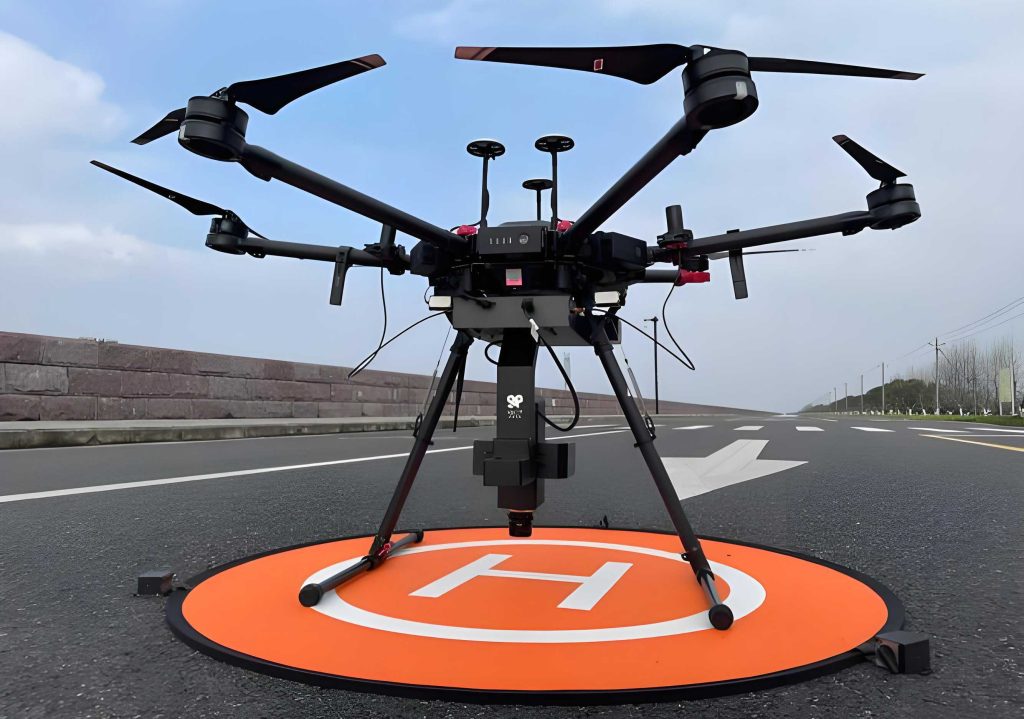
The development of high-speed unmanned aerial vehicles (UAV drones) represents a significant advancement in aerospace technology, offering enhanced maneuverability and strategic capabilities. As these platforms evolve, there is an increasing demand for onboard systems that are lighter, more efficient, and smarter, while simultaneously requiring higher standards of safety and reliability. The braking system is a critical subsystem whose performance directly impacts the safe landing and operational costs of a high-speed UAV drone. Traditional hydraulic braking systems, often criticized for their weight, potential for leaks, and maintenance complexity, are increasingly seen as inadequate for next-generation UAV drones. In contrast, All-Electric Braking Systems (A-EBS), characterized by their simple architecture, fast response, and precise control, are emerging as the preferred solution, aligning with the needs for high reliability and energy efficiency in modern UAV drone platforms.
The core objective of aircraft anti-skid braking control is to modulate the braking pressure in real-time to maximize the frictional force available from the runway surface, thereby bringing the aircraft to a stop efficiently. However, the UAV drone braking system is inherently complex, characterized by strong nonlinearities, high coupling, and time-varying parameters. Key nonlinearities, such as the tire-runway friction characteristics and, crucially, the variable friction behavior of the brake discs themselves, present substantial challenges for designing effective control algorithms. While initial control laws were basic, the widely used “velocity error + Pressure-Bias Modulated (PBM)” control, though reliable, suffers from issues like frequent skidding at low speeds and poor robustness, especially on runways with low adhesion coefficients.
Recent research has focused on overcoming these limitations. Advanced methods include control strategies based on pilot-commanded deceleration, slip-ratio control with self-tuning fuzzy PID, complementary sliding mode control with event triggering, fuzzy logic control targeting optimal slip ratio, and adaptive algorithms like closed-loop PI-type iterative learning combined with particle swarm optimization. While these methods show improvement, they often involve simplifications in system modeling—particularly treating the brake disc friction coefficient as a constant—which can lead to a performance gap between simulation and real-world application. Furthermore, the computational complexity of some intelligent control algorithms (e.g., neural networks) may conflict with the high dynamic response requirements of actual braking, making them challenging to implement in real-time systems.
To address the aforementioned challenges, this paper proposes a hierarchical PID braking control method for UAV drones that explicitly accounts for the variable friction characteristics of carbon/carbon (C/C) brake discs. The contributions are as follows: First, a comprehensive UAV drone braking system model is established, integrating aircraft ground dynamics, wheel dynamics, a tire friction model, and a detailed model of the electromechanical actuator (EMA). Second, a temperature variation model for the brake disc is introduced, coupled with a friction coefficient prediction model based on a Genetic Algorithm-optimized Backpropagation (GA-BP) neural network. This provides a more accurate simulation of the nonlinear friction behavior during braking. Finally, a slip-ratio based hierarchical PID control algorithm is designed and its performance is validated through both simulation analysis and ground inertia bench testing, demonstrating its effectiveness even under adverse conditions like wet runways and wet brake discs.
1. Modeling of the UAV Drone Braking System
Accurate system modeling is fundamental for designing and validating control strategies for the UAV drone. The complete model comprises several interconnected subsystems.
1.1 Aircraft Taxiing Dynamics and Wheel Dynamics
Assuming the UAV drone fuselage and landing gear struts are rigid, and neglecting lateral forces, the longitudinal dynamics during ground roll can be described. The forces acting on the UAV drone include aerodynamic lift and drag, as well as normal and friction forces from the nose and main wheels.
The equation of motion for the UAV drone is:
$$ M \dot{V}_p = -F_{fm} – F_{fn} – F_a $$
where \( M \) is the aircraft mass, \( V_p \) is the longitudinal velocity, \( F_{fm} \) and \( F_{fn} \) are the friction forces on the main and nose wheels, and \( F_a \) is the aerodynamic drag. The vertical force balance and moment balance equations are also considered to solve for the wheel normal loads \( F_{nm} \) and \( F_{nn} \).
The friction force is related to the normal load and the tire-road friction coefficient \( \mu \):
$$ F_{fm} = \mu_m(\lambda) F_{nm}, \quad F_{fn} = \mu_n F_{nn} $$
The aerodynamic forces are given by:
$$ F_l = \frac{1}{2} \rho c_z S_z V_p^2, \quad F_a = \frac{1}{2} \rho c_x S_x V_p^2 $$
where \( \rho \) is air density, \( c_z \) and \( c_x \) are lift and drag coefficients, and \( S_z \) and \( S_x \) are reference areas.
The wheel rotational dynamics are governed by:
$$ J \dot{\omega} = M_f – M_b $$
where \( J \) is the wheel’s moment of inertia, \( \omega \) is the angular velocity, \( M_f \) is the friction torque from the ground, and \( M_b \) is the braking torque. The torques are calculated as:
$$ M_f = R_r \cdot F_{fm}, \quad M_b = 2 N \mu_{bd} K_{bd} P_b $$
Here, \( R_r \) is the wheel rolling radius, \( N \) is the number of brake disc friction surfaces, \( \mu_{bd} \) is the brake disc friction coefficient (a key variable), \( K_{bd} \) is a geometric factor related to disc radii, and \( P_b \) is the applied brake pressure.
1.2 Tire-Runway Friction Model
The slip ratio \( \lambda \) quantifies wheel skid and is defined as:
$$ \lambda = 1 – \frac{R_r \omega}{V_p}, \quad \lambda \in [0, 1] $$
A value of 0 indicates free rolling, while 1 signifies wheel lockup, a condition to be avoided.
The relationship between the friction coefficient \( \mu_m \) and the slip ratio \( \lambda \) is described using the semi-empirical Magic Formula tire model:
$$ \mu_m(\lambda) = \tau_1 \sin(\tau_2 \arctan(\tau_3 \lambda)) $$
The parameters \( \tau_1, \tau_2, \tau_3 \) vary with runway conditions. For a UAV drone operating on dry and wet runways, typical parameters are:
| Runway Condition | \( \tau_1 \) (Peak Factor) | \( \tau_2 \) (Stiffness Factor) | \( \tau_3 \) (Shape Factor) |
|---|---|---|---|
| Dry Runway | 0.8 | 1.5344 | 14.0326 |
| Wet Runway | 0.4 | 2.0192 | 8.2098 |
The \( \mu-\lambda \) curve exhibits a stable region where friction increases with slip ratio until an optimal value \( \lambda_{opt} \), after which friction decreases rapidly, leading to potential lockup. The control goal is to maintain the slip ratio near \( \lambda_{opt} \).
1.3 All-Electric Actuator (EMA) Model
The EMA converts electrical commands into braking pressure. It typically consists of a brushless DC motor (BLDC), a reduction gear, and a ballscrew. The model includes the inverter dynamics, the BLDC motor electrical and mechanical equations, and the ballscrew translation:
Inverter: $$ T_S \frac{du_a}{dt} + u_a = K_S u_c $$
BLDC Motor:
$$ T_e \frac{di_a}{dt} + i_a = \frac{1}{R_a}(u_a – E_a), \quad E_a = C_e \omega_{em} $$
$$ T_m \frac{d\omega_{em}}{dt} = C_m i_a – M_L $$
Ballscrew: $$ \dot{x}_{ad} = \frac{L_{sp}}{2\pi} \omega_{em}, \quad P_b = c_b x_{ad} $$
where \( u_a \) is armature voltage, \( u_c \) is control voltage, \( i_a \) is armature current, \( \omega_{em} \) is motor speed, \( x_{ad} \) is axial displacement, \( L_{sp} \) is lead, and \( c_b \) is brake stack stiffness coefficient.
1.4 Variable Friction Coefficient Model for C/C Brake Discs
The friction coefficient \( \mu_{bd} \) of C/C brake discs is not constant; it varies with temperature, pressure, and slip speed. A predictive model is established by first calculating disc temperature change and then using a GA-BP neural network to predict \( \mu_{bd} \).
1.4.1 Temperature Model
The temperature change \( \Delta T \) of the brake disc is determined by the net heat flow:
$$ \Delta T = \frac{q_{tr} – q_{td} – Q_{out}}{c_{C/C} m_{C/C}} $$
where \( c_{C/C} \) and \( m_{C/C} \) are the specific heat and mass of the C/C disc.
- Frictional Heating (\( q_{tr} \)): $$ q_{tr} = \mu_{bd} P_e V_e = \mu_{bd} P_e \omega r_e $$
- Heat Dissipation (\( q_{td} \)): Includes forced convection (from disc rotation) and natural convection, calculated using Nusselt number correlations: $$ q_{td} = h_{td}(T – T_0), \quad h_{td} = \frac{\lambda^* \text{Nu}}{L_0} $$
- Water Evaporation Cooling (\( Q_{out} \)) (for wet discs): Modeled based on evaporation rate: $$ Q_{out} = E(T) S_w \Delta t L_v $$
1.4.2 GA-BP Neural Network Friction Predictor
A BP neural network is trained to predict \( \mu_{bd} \) using inputs: disc temperature \( T \), brake pressure \( P_b \), and wheel speed \( \omega \). A Genetic Algorithm optimizes the initial weights and thresholds of the BP network to improve prediction accuracy and convergence. The network structure has 3 input neurons, 7 hidden neurons, and 1 output neuron. The training uses experimental data from inertia bench tests.
2. Design of the Hierarchical PID Controller for UAV Drone
The proposed hierarchical PID control system for the UAV drone consists of two main modules: the Basic Braking Module and the Anti-skid Braking Module. The Basic Braking Module is further divided into a Baseline Braking sub-module and a Dynamic Adjustment Braking sub-module. The overall control architecture is designed to efficiently utilize runway adhesion while preventing wheel lockup.
The controller’s total braking command \( S_{total} \) to the EMA is computed as:
$$ S_{total} = i \cdot (S_1 + S_2) – S_3 $$
where \( S_1 \) is the baseline braking amount (a constant), \( S_2 \) is the dynamic adjustment amount, \( S_3 \) is the anti-skid braking amount, and \( i \) is a basic braking adjustment coefficient.
- When \( \lambda < \lambda_f \) (Anti-skid threshold): Basic Braking Module is active (\( S_1, S_2 \)), Anti-skid Module is off (\( S_3 = 0 \)).
- When \( \lambda \geq \lambda_f \): Basic Braking Module is suspended, Anti-skid Module is active (\( S_3 > 0 \)).
2.1 Basic Braking Module
2.1.1 Baseline Braking (\( S_1 \)): A pre-determined constant value obtained from fixed-pressure inertia bench tests. It provides a minimum braking force to ensure basic deceleration without causing skid under any nominal condition.
2.1.2 Dynamic Adjustment Braking (\( S_2 \)): This is the core of the hierarchical PID, responsible for tracking the target slip ratio \( \lambda_m \). It uses a PID controller whose gains are segmented based on the current slip ratio error \( e_\lambda = \lambda_m – \lambda \):
$$ S_2 = K_{p\_dr} e_\lambda + K_{i\_dr} \int e_\lambda dt + K_{d\_dr} \frac{de_\lambda}{dt} $$
The proportional and integral gains vary with the slip ratio:
$$ K_{p\_dr}(\lambda) = \begin{cases}
K_{p1} (\lambda – \lambda_p) + K_{p2} (\lambda_m – \lambda_p), & 0 < \lambda < \lambda_p \\
K_{p2} (\lambda_m – \lambda), & \lambda \ge \lambda_p
\end{cases} $$
$$ K_{i\_dr}(\lambda) = \begin{cases}
K_{i1} (\lambda_m – \lambda), & 0 < \lambda < \lambda_q \\
K_{i2} (\lambda_m – \lambda), & \lambda \ge \lambda_q
\end{cases} $$
$$ K_{d\_dr} = K_d (\lambda_m – \lambda) $$
where \( \lambda_p \) and \( \lambda_q \) are slip ratio boundaries for gain switching. This hierarchical tuning allows for aggressive control at low slip ratios (high \( K_p \), low \( K_i \)) and more conservative, stable control at higher slip ratios (lower \( K_p \), higher \( K_i \)), optimizing performance across different phases of UAV drone braking.
2.2 Anti-Skid Braking Module
This module activates when a skid is detected (\( \lambda \geq \lambda_f \)). It calculates a negative braking command \( S_3 \) to rapidly reduce pressure and break the skid. It also computes the initial value \( i_0 \) for the adjustment coefficient \( i \), which slows down the re-application of braking force after a skid event, preventing repeated deep skids.
Anti-skid Braking Amount (\( S_3 \)):
$$ S_3 = K_{p\_skid} (\lambda – \lambda_f) + K_{i\_skid} \int (\lambda – \lambda_f) dt + K_{d\_skid} \frac{d(\lambda – \lambda_f)}{dt} $$
The integral gain \( K_{i\_skid} \) is piecewise constant based on the severity of the skid:
$$ K_{i\_skid} = \begin{cases}
1, & 0 \le \lambda – \lambda_f < 0.1 \\
1.5, & 0.1 \le \lambda – \lambda_f < 0.2 \\
0, & \lambda – \lambda_f \ge 0.2
\end{cases} $$
Basic Braking Adjustment Coefficient (\( i \)):
The initial value \( i_0 \) after a skid is: $$ i_0 = \frac{500 – S_{3max}}{400}, \quad (0 < S_{3max} < 250) $$
where \( S_{3max} \) is the maximum \( S_3 \) value in that skid cycle. The coefficient \( i \) then recovers linearly over time until it reaches 1:
$$ i(t) = \begin{cases}
i_0 + 2(t – t_0), & i < 1 \\
1, & i \ge 1
\end{cases} $$
where \( t_0 \) is the time the anti-skid module deactivates.
3. Simulation and Experimental Analysis for UAV Drone Braking
3.1 Simulation Setup and Test Bench
A high-fidelity simulation model of the UAV drone braking system was built in MATLAB/Simulink, incorporating all previously described sub-models. The target slip ratio \( \lambda_m \) was set to 0.06, and the anti-skid threshold \( \lambda_f \) to 0.13, based on preliminary inertia bench tests. The simulation step was 0.005 s. Key simulation parameters for the UAV drone are listed below:
| Parameter | Value | Parameter | Value |
|---|---|---|---|
| Aircraft Mass \( M \) | 3500 kg | Wheel Inertia \( J \) | 0.4 kg·m² |
| Initial Speed \( V_{p0} \) | 78 m/s | Wheel Radius \( R_r \) | 0.2 m |
| Brake Stack Stiffness \( c_b \) | 7×10⁵ N/m | Motor Back-EMF Const \( C_e \) | 0.132 |
Experimental validation was conducted on a ground inertia brake test bench. The bench simulates aircraft landing by spinning a large inertia flywheel to the equivalent touchdown speed, applying a radial load to the test wheel against the flywheel, and then initiating braking. The bench used had a maximum energy capacity of 4 MJ.
3.2 Comparison: Hierarchical PID vs. PD+PBM for UAV Drone
Simulations compared the proposed hierarchical PID controller against a conventional PD+PBM controller under four critical UAV drone operating conditions: Dry Runway/Dry Disc (DR/DD), Wet Runway/Dry Disc (WR/DD), Dry Runway/Wet Disc (DR/WD), and Wet Runway/Wet Disc (WR/WD).
Results Summary:
The hierarchical PID controller demonstrated superior performance and stability across all conditions. While PD+PBM worked acceptably on DR/DD, it exhibited frequent skidding and instability on wet or low-friction scenarios (WR/DD, DR/WD, WR/WD). In contrast, the hierarchical PID controller maintained smooth deceleration with minimal or no skidding. For instance, on the worst-case WR/WD condition, PD+PBM caused multiple skids until the speed dropped significantly, whereas hierarchical PID induced only one minor skid event before stable braking.
3.3 Validation: Hierarchical PID Simulation vs. Experiment
The hierarchical PID controller was tested on the inertia bench. The results for the four conditions showed strong agreement between simulation and experiment, validating the models and the controller.
Key Observations:
1. DR/DD: Both simulation and experiment showed stable braking. Slip ratio quickly converged to ~0.06. The friction coefficient and braking torque rose to a peak as the disc reached optimal temperature, then slightly decreased (thermal fade), causing a slight dip in slip ratio. The integral action in the dynamic adjustment module compensated effectively.
Simulation: Braking distance 739.5 m, time 18.97 s, avg. deceleration 4.10 m/s².
Experiment: Braking distance 741.6 m, time 19.02 s, avg. deceleration 4.09 m/s².
2. DR/WD: The braking process had two distinct phases due to water in the disc pores. In the initial phase (~3-4 s), braking torque was low despite high pressure command due to the lubricating water layer and cooling from evaporation. After water evaporated, friction coefficient surged, and the controller rapidly brought the slip ratio to the target. Performance was stable.
Simulation: Braking distance 973.6 m, time 22.49 s, avg. deceleration 3.45 m/s².
Experiment: Braking distance 1046.9 m, time 24.88 s, avg. deceleration 3.13 m/s².
3. WR/DD & WR/WD: On wet runways, the lower available adhesion posed a greater challenge. In the WR/WD experiment, an additional disturbance occurred: tire rubber was deposited on the flywheel surface, further reducing the effective friction coefficient. This caused several minor skids in the high-speed phase. The anti-skid module reacted promptly each time, modulating \( S_3 \) to break the skid. After several adaptations, stable braking was achieved, demonstrating the controller’s robustness against unmodeled disturbances.
The following table summarizes the performance metrics, showing errors between simulation and experiment within 11%.
| Condition | Metric | Simulation | Experiment | Error |
|---|---|---|---|---|
| DR/DD | Braking Distance (m) | 739.50 | 741.60 | 0.28% |
| Braking Time (s) | 18.97 | 19.02 | 0.26% | |
| Avg. Deceleration (m/s²) | 4.10 | 4.09 | 0.24% | |
| DR/WD | Braking Distance (m) | 973.60 | 1046.91 | 7.53% |
| Braking Time (s) | 22.49 | 24.88 | 10.60% | |
| Avg. Deceleration (m/s²) | 3.45 | 3.13 | 9.28% | |
| WR/DD | Braking Distance (m) | 1300.00 | 1355.13 | 4.24% |
| Braking Time (s) | 33.21 | 34.39 | 3.55% | |
| Avg. Deceleration (m/s²) | 2.34 | 2.26 | 3.42% | |
| WR/WD | Braking Distance (m) | 1519.95 | 1587.21 | 4.43% |
| Braking Time (s) | 36.06 | 38.40 | 6.49% | |
| Avg. Deceleration (m/s²) | 2.15 | 2.03 | 5.58% |
4. Conclusion
This paper presented a comprehensive study on an all-electric braking control method for high-speed UAV drones. The main conclusions are:
- A high-fidelity simulation model for the UAV drone braking system was developed, incorporating a GA-BP neural network model to predict the variable friction coefficient of C/C brake discs. The prediction model achieved determination coefficients (R²) of 0.944 and 0.799 for dry and wet disc conditions, respectively. The close agreement between simulation and experimental results (errors within 11%) validates the accuracy of the overall system model.
- A novel hierarchical PID control strategy was designed and implemented. It effectively maintains the wheel slip ratio near the optimal target across diverse and challenging conditions, including wet runways and wet brake discs. The controller demonstrated high deceleration rates, achieving over 2 m/s² even in the most severe WR/WD condition, with a simulation-experiment error of only 5.58% for average deceleration.
- The controller showed good robustness. During experiments on wet runways, where an unmodeled disturbance (tire rubber transfer) further degraded friction, the anti-skid module successfully managed multiple minor skid events, preventing wheel lockup and ensuring the UAV drone came to a safe stop.
The proposed method effectively balances performance and implementability for UAV drone braking systems. Future work will focus on enhancing the system’s autonomy and robustness, potentially by integrating real-time runway condition identification, improving the wet-disc friction prediction model with more training data, and employing advanced state observers to reduce dependency on sensor accuracy and mitigate noise.