
The proliferation of small unmanned aerial vehicles (UAV drones) across civilian, commercial, and military sectors has been remarkable. However, their operational envelope, particularly in noise-sensitive environments like urban areas or during covert missions, is significantly constrained by the acoustic signature they emit. For multi-rotor UAV drones, the dominant noise source is typically the aerodynamic interaction of the rotating blades with the air, generating broadband and tonal components that can be intrusive and limit social acceptance or tactical advantage.
While bio-inspired rotor designs, such as those featuring serrated leading or trailing edges, offer some degree of noise mitigation, their effectiveness is often limited to specific frequency bands and may come with trade-offs in aerodynamic efficiency. An alternative and increasingly considered architecture is the ducted UAV drone. By enclosing the propeller within a shroud, this design offers inherent benefits: it reduces tip vortices and associated losses, improving thrust efficiency; it provides physical protection for the rotor; and it presents a structured surface onto which acoustic treatment can be applied. Nevertheless, a poorly designed duct can itself become a source of resonance and amplified noise due to turbulent interactions.
Acoustic liners, derived from turbofan engine nacelle technology, are a proven method for attenuating noise within ducts. However, their application to small-scale UAV drones introduces severe constraints on weight, volume, and structural integration. Traditional liner materials like porous foams or complex resonator arrays are often too bulky or heavy. This creates a critical research gap: the need for a lightweight, compact, and effective acoustic treatment specifically tailored for the form factor and acoustic environment of small ducted UAV drones.
This paper addresses this gap by proposing, modeling, and validating a novel noise control solution based on Curved Micro-Perforated Panel (CMPP) acoustic liners. Micro-perforated panels (MPPs) are recognized for their efficient sound absorption with minimal material use, making them ideal for weight-critical applications. By curving the MPP to conform to the inner surface of a UAV drone’s duct, we create a CMPP liner that integrates seamlessly without sacrificing internal volume. The core hypothesis is that this CMPP liner will provide significant broadband noise reduction for the ducted UAV drone while maintaining or even enhancing its thrust performance due to improved duct aerodynamics.
Theoretical Foundation and Numerical Modeling of CMPP Liners
The acoustic performance of a CMPP liner is governed by its specific acoustic impedance, which characterizes how it resists and reacts to incident sound waves. A CMPP consists of a thin panel, curved to a specific profile, perforated with a lattice of sub-millimeter holes. When sound waves interact with this structure, the viscous friction of air oscillating within the narrow holes dissipates acoustic energy as heat, providing the absorption mechanism.
The geometry of a CMPP liner’s cross-section is defined by several key parameters, as illustrated in the schematic. Let $W$ represent the axial width of the liner, and $D$ its maximum cavity depth. The curvature is parameterized by the depth $H$ of the point of maximum curvature from a reference chord line, and the offset $O$ of this point along the width $W$. A flat MPP corresponds to the case where $H = 0$ and $O = 0$.
The perforation rate $\sigma$ for a curved panel differs from a flat one. For a flat panel with a square array of holes of diameter $d$ and pitch $b$, the perforation rate $\sigma_0$ is:
$$\sigma_0 = \frac{\pi d^2}{4b^2}$$
For the curved CMPP, the effective perforation rate $\sigma$ is adjusted by the ratio of the curved arc length $L$ to the projected width $W$:
$$\sigma = \frac{W}{L} \sigma_0$$
This adjustment is crucial for accurate modeling.
The specific acoustic impedance $Z$ of the CMPP is the fundamental property dictating its interaction with sound. It is a complex quantity, $Z = R + j\omega M$, where $R$ is the acoustic resistance (responsible for energy dissipation), $M$ is the acoustic mass (related to inertia), $j$ is the imaginary unit, and $\omega = 2\pi f$ is the angular frequency. For a CMPP with circular holes of thickness $t$, considering grazing flow effects represented by the Mach number $M_{ag}$, the resistance and mass are given by:
$$R = \frac{32 \eta t}{\sigma d^2} \left[ \left(1 + \frac{k^2}{32}\right)^{1/2} + \frac{\sqrt{2}}{32} \frac{k d}{t} \right] + \frac{0.15 M_{ag}}{\sigma}$$
$$M = \frac{\rho t}{\sigma} \left[ 1 + \left(1 + \frac{k^2}{2}\right)^{-1/2} + 0.85 \frac{d}{t} F(M_{ag}) \right]$$
where $\eta$ is the dynamic viscosity of air, $\rho$ is the air density, $k = d\sqrt{\rho \omega / 4\eta}$ is the perforation constant, and $F(M_{ag}) = [1 + (12.6 M_{ag})^3]^{-1}$ is a flow correction factor. These equations form the basis for modeling the CMPP’s boundary condition in a numerical simulation.
A finite element model was established to simulate the acoustic field within and around the CMPP liner. The domain comprised an acoustic air volume and the structural domain of the curved panel shell. The impedance boundary condition derived from $Z$ was applied at the interface between the air and the CMPP structure. A point source was placed at the geometric center of the liner cavity to simulate the noise generation from the UAV drone’s motor-propeller assembly. Perfectly Matched Layers (PMLs) were applied at the outer boundaries of the acoustic domain to simulate anechoic conditions and prevent spurious reflections. The mesh was refined to ensure at least eight elements per wavelength at the highest frequency of interest, guaranteeing solution accuracy. The key parameters for the parametric study are summarized in Table 1.
| Liner ID | Max Curvature Depth $H$ (mm) | Curvature Offset $O$ (mm) | Panel Thickness $t$ (mm) | Hole Diameter $d$ (mm) | Perforation Rate $\sigma$ (%) |
|---|---|---|---|---|---|
| CMPP1 | 30 | 7.5 | 1.0 | 0.6 | 1.6 |
| CMPP2 | 20 | 7.5 | 1.0 | 0.6 | 1.6 |
| CMPP3 | 10 | 7.5 | 1.0 | 0.6 | 1.6 |
| CMPP4 (Flat) | 0 | 7.5 | 1.0 | 0.6 | 1.6 |
| CMPP5 | 30 | 20 | 1.0 | 0.6 | 1.6 |
| CMPP6 | 30 | 10 | 1.0 | 0.6 | 1.6 |
| CMPP7 | 30 | 7.5 | 1.0 | 0.6 | 1.6 |
| CMPP8 | 30 | 0 | 1.0 | 0.6 | 1.6 |
Parametric Influence of Curvature on Liner Performance
The numerical study focused on two primary curvature parameters: the maximum depth $H$ and its lateral offset $O$. The sound pressure level (SPL) was monitored at several observer points radially and axially from the source. The overall attenuation performance can be quantified by an Insertion Loss (IL) metric, calculated as the difference in SPL at a given point with and without the liner. For a specific frequency $f$, the IL at observer point $i$ is:
$$IL_i(f) = SPL_{i,\text{hard}}(f) – SPL_{i,\text{CMPP}}(f)$$
A positive IL indicates noise reduction.
The influence of the curvature depth $H$ is significant. Table 2 summarizes the average IL over a mid-frequency band (1000-2000 Hz) for liners CMPP1-CMPP4. The results indicate that introducing curvature (increasing $H$ from 0) generally enhances performance, but an optimal depth exists. Excessively deep curvature can create focusing effects or alter the effective cavity resonance, potentially degrading performance at certain frequencies. The simulations showed that CMPP2 ($H=20$ mm) provided the most consistent broadband attenuation.
| Observer Location | CMPP1 (H=30mm) | CMPP2 (H=20mm) | CMPP3 (H=10mm) | CMPP4 (H=0mm, Flat) |
|---|---|---|---|---|
| Radial, 30mm | 3.2 | 4.1 | 2.8 | 1.5 |
| Axial, 30mm | 2.8 | 3.5 | 2.5 | 1.2 |
| Radial, 60mm | 2.5 | 3.1 | 2.1 | 0.9 |
The influence of the curvature offset $O$ is more subtle but crucial. When the point of maximum curvature is aligned with the acoustic source ($O=0$, as in CMPP8), the liner’s geometry appears more symmetric to the sound field. The numerical results, quantified in Table 3, demonstrate that this alignment ($O=0$) consistently yields the highest insertion loss across all observer points. This suggests that symmetric energy distribution relative to the liner’s absorbing surface maximizes dissipation. The configuration with $O=0$ was therefore selected as the optimal design for the subsequent experimental phase on the UAV drone.
| Observer Location | CMPP5 (O=20mm) | CMPP6 (O=10mm) | CMPP7 (O=7.5mm) | CMPP8 (O=0mm) |
|---|---|---|---|---|
| Radial, 30mm | 2.5 | 3.0 | 3.2 | 4.5 |
| Axial, 30mm | 2.2 | 2.7 | 2.8 | 4.0 |
| Radial, 60mm | 1.9 | 2.3 | 2.5 | 3.4 |
Experimental Validation on a Ducted UAV Drone Platform
To validate the numerical findings, a bespoke CMPP liner, termed the C-Liner, was fabricated and integrated into a custom ducted UAV drone test article. The C-Liner was manufactured using a 1.0 mm thick polycarbonate sheet, laser-drilled with a 0.6 mm diameter hole pattern to achieve a 1.6% perforation rate, and then thermoformed into the optimal curved shape with $H=30$ mm and $O=0$ mm. This liner was fitted onto the interior wall of a cylindrical duct shroud housing a standard 1400 kV brushless motor and a 20.3 cm diameter two-bladed propeller.
The experimental setup consisted of a rigid test stand to hold the ducted UAV drone assembly. Acoustic measurements were taken using a precision sound level meter with a 1/2-inch microphone fitted with a spherical windscreen to minimize flow noise contamination. Data was acquired at a 48 kHz sampling rate. The microphone was positioned at three standard locations relative to the UAV drone: 1) directly above the duct, 2) directly below, and 3) laterally at a distance of 80 cm. An infrared laser tachometer monitored the propeller rotational speed (RPM).
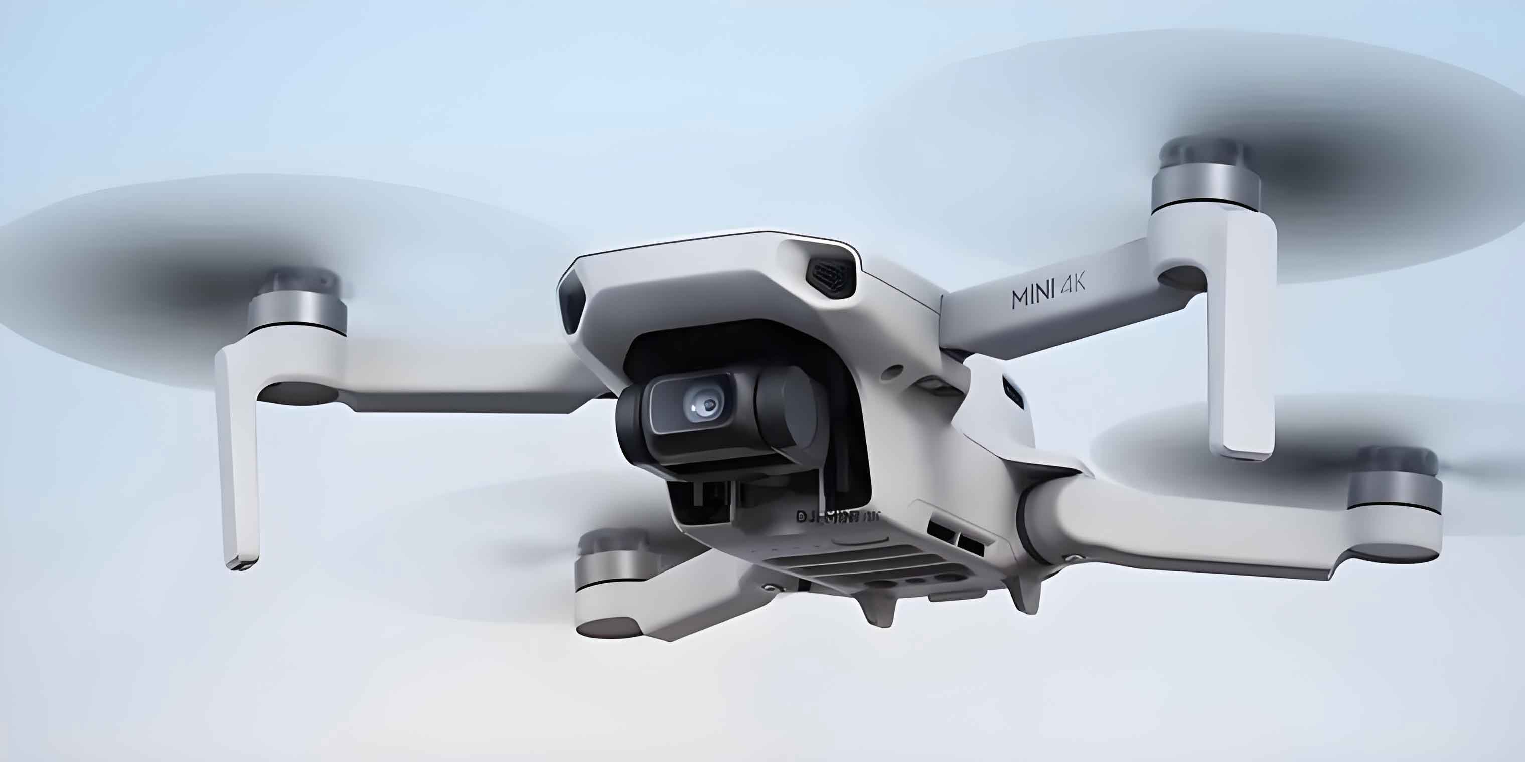
The primary metric for evaluation was the Overall A-weighted Sound Pressure Level (OASPL), which weights the frequency spectrum according to human hearing sensitivity. For each test condition (RPM, liner configuration), three repeated measurements $L_1, L_2, L_3$ were taken, and the mean OASPL was calculated as:
$$L_{OA} = 10 \log_{10}\left( \frac{1}{3} (10^{L_1/10} + 10^{L_2/10} + 10^{L_3/10}) \right)$$
The noise reduction $\Delta L_{OA}$ provided by the C-Liner was then:
$$\Delta L_{OA} = L_{OA, \text{Baseline Duct}} – L_{OA, \text{C-Liner Duct}}$$
The experimental results conclusively demonstrated the efficacy of the C-Liner. As shown in Table 4, the CMPP-based liner provided significant noise reduction across all measurement positions and over a range of operational speeds for the UAV drone. The reduction was most pronounced at higher RPMs, where noise levels are generally greater, with a maximum reduction of 2.1 dB(A) observed. Spectral analysis confirmed that the attenuation was broadband, with particular effectiveness in the mid-to-high frequency range (approximately 1 kHz to 8 kHz), which is often the most perceptible and annoying part of small UAV drone noise.
| Propeller Speed (RPM) | Position 1 (Above) | Position 2 (Below) | Position 3 (Lateral) | Average Reduction |
|---|---|---|---|---|
| 2000 | 0.8 | 0.5 | 0.7 | 0.67 |
| 3000 | 1.5 | 1.0 | 1.3 | 1.27 |
| 4000 | 2.1 | 1.4 | 1.8 | 1.77 |
| 5000 | 2.0 | 1.5 | 1.9 | 1.80 |
Adaptability to Different Rotor Designs and Impact on Thrust
A critical question for practical application is whether the CMPP liner’s performance is specific to one rotor type or if it offers broad adaptability. To investigate this, the C-Liner was tested with four distinct propeller designs mounted on the same UAV drone motor: a standard two-blade, a three-blade, a bio-inspired leading-edge serrated blade, and a novel ring-shaped propeller. The results, summarized in Table 5, indicate that the C-Liner provides positive noise reduction for all propeller types, demonstrating good general adaptability. The magnitude of reduction varies, likely due to differences in the spectral content and directivity of the noise generated by each rotor. This finding is significant, suggesting that a single, optimized CMPP liner design can be effective for a family of ducted UAV drones employing different rotors.
| Rotor Type | Baseline OASPL (dB(A)) | C-Liner OASPL (dB(A)) | Noise Reduction $\Delta L_{OA}$ (dB(A)) |
|---|---|---|---|
| Two-Blade | 78.5 | 76.7 | 1.8 |
| Three-Blade | 80.1 | 78.5 | 1.6 |
| Serrated Blade | 77.8 | 76.2 | 1.6 |
| Ring Propeller | 76.2 | 74.1 | 2.1 |
Perhaps the most surprising and beneficial result was the effect of the C-Liner on the thrust performance of the ducted UAV drone. It was hypothesized that adding any liner might slightly disrupt flow and reduce efficiency. Contrary to this, static thrust tests revealed a consistent and notable increase in thrust when the C-Liner was installed. The thrust $T$ was measured using a high-precision load cell. The percentage thrust increase $\Delta T_{\%}$ is defined as:
$$\Delta T_{\%} = \left( \frac{T_{\text{C-Liner}} – T_{\text{Baseline}}}{T_{\text{Baseline}}} \right) \times 100\%$$
As detailed in Table 6, the C-Liner enhanced thrust across all tested RPMs, with an improvement of up to 20% at 5000 RPM. This can be attributed to the CMPP’s surface acting as a flow conditioner. The micro-perforations and the curved surface may help stabilize the boundary layer within the duct, reducing flow separation and associated losses, thereby making the duct itself more aerodynamically efficient. This dual benefit of noise reduction and thrust enhancement is a major advantage for the CMPP liner technology in UAV drone applications.
| Propeller Speed (RPM) | Baseline Duct Thrust (g) | C-Liner Duct Thrust (g) | Thrust Increase $\Delta T_{\%}$ (%) |
|---|---|---|---|
| 2000 | 52 | 58 | 11.5 |
| 3000 | 98 | 112 | 14.3 |
| 4000 | 155 | 185 | 19.4 |
| 5000 | 200 | 240 | 20.0 |
Conclusion and Future Perspectives
This comprehensive study has successfully established the Curved Micro-Perforated Panel (CMPP) as a highly effective acoustic liner technology for noise control in small ducted UAV drones. Through a rigorous methodology combining theoretical impedance modeling, parametric numerical simulation, and experimental validation, the acoustic and aerodynamic benefits of the design have been quantified.
The key findings are: (1) The curvature of the MPP is a critical design parameter, with the depth $H$ and offset $O$ significantly influencing the insertion loss; an optimal configuration with the maximum curvature point aligned with the noise source ($O=0$) was identified. (2) Experimental tests on a physical ducted UAV drone platform confirmed substantial broadband noise reduction, with an average OASPL reduction of 1.5-2.1 dB(A) under typical operating conditions, particularly effective in the perceptually important mid-to-high frequencies. (3) The CMPP liner demonstrated good adaptability, providing measurable noise reduction for a variety of common and bio-inspired propeller types used on UAV drones. (4) Most notably, the integration of the CMPP liner led to a significant increase in static thrust—up to 20%—suggesting it improves duct aerodynamics by acting as a boundary layer flow conditioner.
The implications of this research are substantial for the next generation of quiet and efficient UAV drones. The CMPP liner presents a lightweight, compact, and multi-functional solution that directly addresses the core constraints of small-scale aviation. Future work will focus on the inverse design of CMPP liners tailored to the specific acoustic fingerprint of target UAV drone models, potentially using optimization algorithms to tailor the curvature and perforation pattern for maximum attenuation of dominant tonal and broadband components. Furthermore, investigation into the synergistic effects of combining CMPP liners with optimized rotor designs (e.g., serrated blades) could unlock even greater levels of acoustic stealth and operational performance for ducted UAV drones in both civilian and military domains.