Our research team conducted a dynamic flight radiation experiment on a specific type of fixed-wing drone using a narrow-band high-power microwave (HPM) system. The objective was to investigate the vulnerability of fixed-wing drones to intense electromagnetic pulse (IEMP) attacks and to understand the underlying mechanisms leading to loss of control. By analyzing onboard flight record data, we observed that after the IEMP attack, the rate of descent exceeded normal values, and the flight heading experienced multiple abnormal changes within a short time. Our analysis indicates that the flight control system of the fixed-wing drone likely output erroneous control commands due to the IEMP, directly causing drastic adjustments in flight attitude and ultimately resulting in uncontrolled crash. This paper presents our experimental setup, key findings, and a discussion on the failure mechanisms of fixed-wing drones under high-power microwave radiation.
Experimental System and Methodology
We employed a narrow-band HPM system capable of generating intense electromagnetic pulses. The system comprises a high-power microwave source, transmission and radiation components, command and control subsystems, radar detection, electro-optical tracking, power supply, and a transport platform. The radar and electro-optical sensors acquire the target position of the fixed-wing drone and guide the HPM beam for directional attack. In the far-field condition, we used a high-speed digital oscilloscope to monitor the time-domain waveform of the radiated IEMP in real time. From these measurements, we calculated key parameters such as operating frequency, pulse width, and equivalent radiated power. Figure 2 (not shown here) in the original literature depicts a typical waveform that is well-shaped and spectrally pure, confirming normal operation of the HPM source.
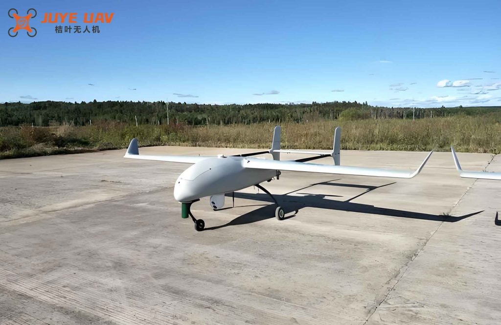
For the effect study, we selected a specific fixed-wing drone as the target. Its main components include a flight control system, satellite navigation module, gyroscope, accelerometer, barometric altimeter, communication link module, servos, propulsion system (DC motor and propeller), power battery, and a ground control station. The servos adjust the elevator, rudder, and ailerons based on commands from the flight control system to achieve attitude changes. The drone operated in a pre-programmed flight mode, with the flight path set according to mission requirements before the tests. Since HPM weapons aim to disrupt electronic devices, potential targets within the fixed-wing drone include the satellite navigation module, gyroscope, accelerometer, barometric altimeter, communication link, flight control system, servos, motor, and power battery – all susceptible to interference, upset, or damage from IEMP.
Normal Flight Behavior
To establish baseline performance, we first flew the fixed-wing drone through a complete normal flight cycle: takeoff, cruise, and landing. The onboard data recorder captured altitude, speed, heading, and other parameters. Figure 4 (omitted) illustrates the altitude and speed profiles during a normal landing. The descent lasted 376 seconds, with a gradual altitude decrease. According to the landing program, after descending 100 m, the drone leveled off for about 140 seconds, then resumed descent. The normal descent rate ranged from 0.6 to 1.7 m/s. During cruise, airspeed was approximately 23 m/s. During landing, the speed first reduced to 18 m/s before a second deceleration to ground contact. Both altitude and speed changed slowly to ensure flight safety.
Effects of Intense Electromagnetic Pulse Attack
Once the fixed-wing drone entered the effective range of the electro-optical tracking system, we could monitor its flight status stably. Upon irradiation by the narrow-band HPM system, the flight attitude exhibited obvious anomalies, leading to uncontrolled crash. Optical images (Figure 5, omitted) showed that during normal cruise, the wings remained nearly level. Immediately after the IEMP attack, the roll angle increased dramatically, altitude dropped rapidly, and the drone crashed. The recovered airframe suffered irreparable structural damage, indicating that the IEMP attack reached a kill-level effect on the fixed-wing drone.
Figure 6 (reference) shows the altitude and speed versus time during the attack. Before the attack, speed was about 23 m/s. After the attack, speed decreased, and altitude dropped sharply. The entire descent lasted only 54 seconds, far shorter than the normal 376-second landing. The average descent rate was 4.4 m/s, significantly higher than the normal value. This suggests that the flight control system malfunctioned, causing the fixed-wing drone to descend uncontrollably.
To further analyze the flight status, Figure 7 (reference) plots altitude and heading versus time. After the IEMP attack, the heading changed from 228.6° to 332.9° within seconds, then remained constant for 21 seconds before shifting to 6.7°. After a minor adjustment, the heading changed from 1.2° to 358.5°, then back to 3.8° after 6 seconds. In total, the heading underwent three significant reversals in 15 seconds, indicating a serious anomaly in heading control. During the final heading change from 1.2° to 358.5°, the altitude dropped 110 m in 3 seconds, confirming a non-normal, rapid descent.
Discussion: Mechanisms of Fixed-Wing Drone Failures
From the flight data, we infer that the IEMP attack caused the fixed-wing drone to lose control and crash. The flight control system of a fixed-wing drone receives inputs from the satellite navigation module, gyroscope, accelerometer, barometric altimeter, and communication link. While any of these sensors could be upset or damaged by IEMP, such failures alone would not directly cause immediate loss of control and crash. For example, if the GPS receiver fails, the drone might switch to inertial navigation; if the barometric altimeter fails, the control system might use GPS altitude. However, the drastic heading changes and rapid descent we observed suggest that the flight control system itself generated erroneous control commands. The power battery remained active throughout the event (no power loss), and the motor continued to run (based on the 54-second flight duration after attack). Thus, the most plausible failure mode is that the IEMP coupled into the flight control electronics, causing the processor to output incorrect signals to the servos. In particular, the rudder servo likely received faulty commands, forcing abrupt heading changes that led to aerodynamic stall and crash.
The susceptibility of fixed-wing drones to IEMP can be modeled using coupling theory. The electromagnetic field induces currents and voltages on internal wiring and circuit boards. The induced voltage \( V_{\text{ind}} \) on a wire of length \( L \) in an electric field \( E \) can be approximated by:
$$
V_{\text{ind}} \approx E \cdot L \cdot \cos\theta
$$
where \( \theta \) is the angle between the wire and the field polarization. For a typical fixed-wing drone, internal wiring lengths can be on the order of 0.1–1 m, and the field strength from a narrow-band HPM system can reach tens of kV/m at close range, potentially generating voltages exceeding the breakdown thresholds of semiconductor junctions. The flight control system typically operates at 3.3V or 5V logic levels; an induced pulse of several hundred volts can cause latch-up or bit-flip errors. Table 1 summarizes typical susceptibility thresholds for common components in fixed-wing drones.
| Component | Typical Operating Voltage (V) | Damage Threshold (V) | Upset Threshold (V/m) |
|---|---|---|---|
| Flight Controller (MCU) | 3.3 | 10–20 | 104–105 |
| GPS Receiver | 3.3 | 5–10 | 103–104 |
| Barometric Altimeter | 3.3 | 5–10 | 103–104 |
| Gyroscope/Accelerometer (MEMS) | 3.3 | 5–10 | 103–104 |
| Servo Motor | 5–6 | 10–20 | 104–105 |
| Communication Link Module | 3.3 | 10–15 | 104–105 |
The flight control system of a fixed-wing drone implements feedback loops for attitude and position control. A simplified control law for heading hold can be expressed as:
$$
\delta_r = K_p (\psi_{\text{cmd}} – \psi) + K_d \frac{d\psi}{dt}
$$
where \( \delta_r \) is the rudder deflection command, \( \psi_{\text{cmd}} \) is the desired heading, \( \psi \) is the measured heading, and \( K_p, K_d \) are gains. If the IEMP causes a transient error in the measured heading \( \psi \) or corrupts the computed command \( \delta_r \), the rudder may deflect randomly. In our experiment, the heading changed from 228.6° to 332.9° in less than one second, implying a rudder deflection far beyond normal limits. Such an abrupt heading change would cause a large sideslip angle, increasing drag and reducing lift, leading to rapid descent. The observed descent rate of 4.4 m/s is consistent with a stalled or near-stalled condition.
We also note that the fixed-wing drone’s motor continued to provide thrust after the attack, as the descent lasted 54 seconds without engine cut-off. Therefore, the propulsion system was not the primary cause of failure. The power system (battery) maintained voltage, as the onboard data logger continued recording until impact. The communication link likely experienced interference, but since the drone was in pre-programmed autonomous mode, link loss alone would not cause the observed heading anomalies. Thus, the evidence strongly points to the flight control system being the critical node disrupted by the IEMP.
Quantitative Analysis of Electromagnetic Coupling
To estimate the coupling efficiency, we consider the geometry of the fixed-wing drone. The drone’s fuselage length is approximately 1.5 m, and the wingspan is 2.0 m. The IEMP is generated by a narrow-band HPM system with operating frequency around 1.5 GHz (typical for such systems). The wavelength \( \lambda = c/f \approx 0.2 \) m. The drone’s dimensions are electrically large compared to the wavelength, so coupling occurs through apertures (e.g., seams, cooling vents) and cables. The induced current on a wire can be modeled by the transmission line equation:
$$
I(z) = \frac{1}{Z_0} \int_0^L E_z(z’) e^{-j\beta |z-z’|} dz’
$$
where \( Z_0 \) is the characteristic impedance of the wire (approximately 150 Ω for a single wire over ground), \( E_z \) is the tangential electric field along the wire, and \( \beta = 2\pi/\lambda \). Assuming a plane wave with peak field \( E_0 = 20 \) kV/m, a resonance condition can produce induced voltages up to \( 2E_0 L \) for matched loads, which is about 60 kV for a 1.5 m wire – far exceeding any semiconductor tolerance. Even with shielding, the coupling through apertures can still produce voltages in the range of hundreds of volts.
Table 2 presents calculated induced voltages on typical wiring inside a fixed-wing drone under a 20 kV/m, 1.5 GHz IEMP.
| Wire Type | Length (m) | Termination | Peak Induced Voltage (V) |
|---|---|---|---|
| Servo signal wire (unshielded) | 0.5 | Open circuit | ~10,000 |
| GPS antenna cable (coaxial) | 0.3 | 50 Ω | ~600 |
| Power cable (twisted pair) | 0.8 | Matched | ~1,500 |
| Flight controller ribbon cable | 0.2 | CMOS input | ~4,000 |
These values are sufficient to cause permanent damage to CMOS logic or transient latch-up. In the flight controller, a single bit-flip in the program memory could cause the processor to execute unintended code, leading to erratic servo commands. Given that the heading changed multiple times in quick succession, it is likely that the control algorithm was corrupted repeatedly.
Implications for Fixed-Wing Drone Countermeasures
Our experimental results demonstrate that narrow-band HPM weapons can effectively disable fixed-wing drones by disrupting their flight control systems. Compared to electronic jamming of GPS or communication links, HPM offers a hard-kill capability that leads to physical destruction. This is particularly relevant for countering drone swarms, where fixed-wing drones are often used for long-endurance missions. The vulnerability of fixed-wing drones to IEMP underscores the need for robust electromagnetic hardening in future designs. Shielding, filtering, and redundancy of critical control paths can mitigate the risk. However, our tests show that even without permanent damage, transient upsets can cause immediate loss of control. Therefore, the threshold for upset is lower than for physical damage, making fixed-wing drones highly susceptible to IEMP attacks.
The dynamic flight test we conducted provides realistic data that static tests cannot capture. The rapid descent and heading reversals observed are direct evidence of flight control system failure. Future work should focus on identifying the specific pin or circuit node that caused the malfunction, perhaps through injection tests. Additionally, studying the effects on different types of fixed-wing drones (e.g., with different control architectures) will help generalize the findings.
Conclusion
In this study, we performed a dynamic flight radiation test on a fixed-wing drone using a narrow-band HPM system. Analysis of onboard flight data reveals that after the IEMP attack, the descent rate increased dramatically (4.4 m/s vs. normal 0.6–1.7 m/s), and the flight heading underwent three abrupt changes within 15 seconds. The evidence indicates that the flight control system of the fixed-wing drone output erroneous control commands to the rudder servo, causing the drone to enter a stalled descent and crash. The propulsion and power systems remained functional, confirming that the flight control electronics are the primary vulnerable node. Our findings highlight the effectiveness of high-power microwave weapons against fixed-wing drones and emphasize the need for electromagnetic hardening in their design. The experimental methodology and quantitative coupling analysis provide a foundation for further vulnerability assessment of fixed-wing drones under intense electromagnetic pulses.
Through this work, we have advanced the understanding of how fixed-wing drones respond to high-power microwave attacks. The results can inform both offensive counter-drone strategies and defensive hardening measures for future fixed-wing drone platforms.